
Subscribe to Our Youtube Channel
Related Manuals for Dahua Technology DH-PFS4210-8GT-DP


Summary of Contents for Dahua Technology DH-PFS4210-8GT-DP
- Page 1 Dahua Gigabit Industrial Managed Switch Quick Start Guide Dahua Gigabit Industrial Managed Switch Quick Start Guide V1.0.2 ZHEJIANG DAHUA VISION TECHNOLOGY CO., LTD.
- Page 2 Dahua Gigabit Industrial Managed Switch Quick Start Guide Important Safeguards and Warnings Please read the following safeguards and warnings carefully before using the product in order to avoid damages and losses. Attentions Do not expose the device to lampblack, steam or dust. Otherwise it may cause fire or electric shock. ...
-
Page 3: Table Of Contents
Device Structure ....................- 6 - Side Panel ........................- 6 - Front Panel ........................- 6 - 2.2.1 DH-PFS4210-8GT-DP ....................- 6 - 2.2.2 DH-PFS4410-6GT-DP ....................- 8 - Installation Description .................. - 10 - Installation Steps ......................- 10 - Wiring .......................... -
Page 4: Overview
-40℃~+75℃ wide temperature design. Network management based on SNMP. Low power consumption with full load. 1.3 Typical Application It is to take the DH-PFS4210-8GT-DP switch as an example to introduce the typical networking scene, which is shown in Figure 1-1. - Page 5 Dahua Gigabit Industrial Managed Switch Quick Start Guide Figure 1-1...
-
Page 6: Device Structure
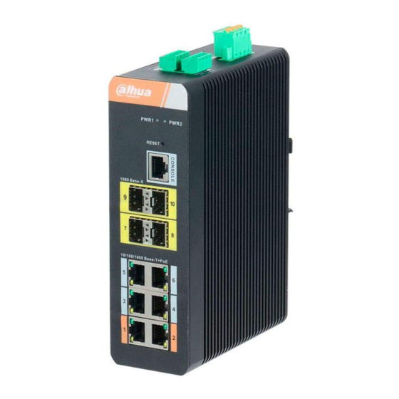
Power port, dual power backup access. Supports DC 48V-DC 57V power input. RS485 A1B1 and A2B2, two pairs of RS485 ports. G and Z, a pair of alarm input port. NO and C, a pair of alarm output port. GND. Table 2-1 2.2 Front Panel 2.2.1 DH-PFS4210-8GT-DP... - Page 7 Dahua Gigabit Industrial Managed Switch Quick Start Guide Figure 2-2 Please refer to Table 2-2 and Table 2-3 for the details of indicator light and port respectively. Indicator light Note Color Device status PWR1/PWR2 Power status indicator Green Power connection is normal. Table 2-2 Port Note...
-
Page 8: Dh-Pfs4410-6Gt-Dp
Dahua Gigabit Industrial Managed Switch Quick Start Guide 2.2.2 DH-PFS4410-6GT-DP Figure 2-3 Please refer to Table 2-4 and Table 2-5 for the details of indicator light and port respectively. Indicator light Note Color Device status PWR1/PWR2 Power status indicator Green Power connection is light normal. - Page 9 Dahua Gigabit Industrial Managed Switch Quick Start Guide Port Note CONSOLE System login setting port. 1/2/3/4/5/6 6 RJ45 10M/100M/1000M self-adaptive PoE network ports. 7/8/9/10 4 1000M optical fiber ports. RESET Long press for more than 5s to realize default config function. Table 2-5...
-
Page 10: Installation Description
Dahua Gigabit Industrial Managed Switch Quick Start Guide 3 Installation Description 3.1 Installation Steps The device supports DIN-rail mount. Hang the switch hook on the rail, press the switch to make the buckle stuck into the rail, which is shown in Figure 3-1. -
Page 11: Console Port
Dahua Gigabit Industrial Managed Switch Quick Start Guide Figure 3-3 The cable connection of RJ45 connector conforms to the standard 568B (1-orange white, 2-orange, 3-green white, 4-blue, 5-blue white, 6-green, 7-brown white, 8-brown). 3.2.2 Console Port Please refer to Figure 3-4 for the console port. Figure 3-4 Console port is shown in Figure 3-4, use RJ45-DB9 cable to connect device console port and 9-pin serial port which controls the computer. -
Page 12: Sfp Ethernet Port
Dahua Gigabit Industrial Managed Switch Quick Start Guide One end of RJ45-DB9 cable is RJ45 connector, which needs to be inserted into the Console port of the device; the other end is DB9 plug, which needs to be inserted into the 9-pin serial port which controls the computer. -
Page 13: Gnd
Dahua Gigabit Industrial Managed Switch Quick Start Guide and confirm the antistatic wrist is well linked to the surface of the gloves. Step 2 Lift the handle of SFP module upward vertically and make it get stuck to the top hook, hold the SFP module on both sides and push it gently into the SFP slot till the SFP module is firmly connected to the slot (it can feel that both the top and bottom spring strip of the SFP module are firmly stuck with the SFP slot). - Page 14 Dahua Gigabit Industrial Managed Switch Quick Start Guide Figure 3-9 Please refer to Table 3-2 for the definition of power terminal. Signal Name DC Wiring Definition PWR2- PWR2+ PWR1- PWR1+ Table 3-2 It provides power for the device by connecting power terminal to power cable. Redundant power input supports two channels power which are PWR0 and PWR1, you can select the other power to continue to provide power when one channel of power breaks down, which greatly improves the reliability of network operation.
- Page 15 Dahua Gigabit Industrial Managed Switch Quick Start Guide Figure 3-10 Step 4 Insert the plug which is connected to power cable back to the corresponding power terminal socket of the device. Step 5 Connect the other end of power cable to the corresponding external power supply system according to the power supply requirement marked on the device, and check if the corresponding power indicator light of the device is on, it means power connection is correct if the light is on.
-
Page 16: Alarm Terminal
Dahua Gigabit Industrial Managed Switch Quick Start Guide 3.2.6 Alarm Terminal Figure 3-11 The alarm terminal is located on the side panel of the device, which is used for alarm output. When the device works normally, the alarm relay NO end is closed and NC end is disconnected; when alarm happens, the NO end is disconnected and the NC end is closed. -
Page 17: Quick Operation
4 Quick Operation It is to introduce VLAN config briefly in this chapter, please refer to corresponding command line manual for other detailed config. 4.1 First Login via Console Port It is the most basic way to log in the local interface via Console port; it is also the method to configure other ways to log in the device. - Page 18 Step 5 The device is powered on, it displays device self-check info on the terminal, and it will prompt users to press Enter button after self-check is over, then it will display username and password input prompt. Step 6 Input username and press Enter button. Step 7 Input password and press Enter button.
-
Page 19: Device Factory Default Config
00:00:00 Using device: /dev/mtd7 00:00:01 Mounted /dev/mtd7 00:00:01 Loading stage2 from NAND file 'n6G5Xw' 00:00:05 Overall: 4195 ms, ubifs = 748 ms, rootfs 3422 ms of which xz = 0 ms of which untar = 0 ms Starting application...wuxuwuxu Using existing mount point for /switch/ system time:2017-10-14 17:59:53 W icfg 18:00:22 71/icfg_commit_tftp_load_and_trigger#2695: Warning: TFTP get bringup-config: Operation timed out. - Page 20 ranging from 2 to 4094. The switch creates VLAN1 under the default circumstance and VLAN1 cannot be deleted. Application Example Networking Requirement There are two users, user 1 and user 2. These two users need to be in different VLAN because the network function and environment they use are different.
- Page 21 Note This user’s manual is for reference only. Slight difference may be found in user interface. All the designs and software here are subject to change without prior written notice. All trademarks and registered trademarks are the properties of their respective owners. ...
Need help?
Do you have a question about the DH-PFS4210-8GT-DP and is the answer not in the manual?
Questions and answers