Table of Contents
Advertisement
Quick Links
USER'S MANUAL
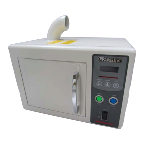
Compact Excimer Lamp Light Source
Read this user's manual carefully before attempting to operate or service
this product.
Do not attempt to operate or service this product until you completely
understand the contents of this manual.
Those responsible for this product should not allow personnel to operate or
service it unless they thoroughly understand this manual.
Keep this manual near the product for easy reference when needed.
If this manual is lost or damaged, promptly order a replacement copy from
our sales office or sales representative.
If transferring this product to another party, make sure that this manual is
included along with the product.
The contents of this manual are subject to change without prior notice due
to product improvement.
Reproduction or copying of this manual in part or in whole is prohibited
without the permission of Hamamatsu Photonics.
EX-mini L12530
@W2-0245-1
Advertisement
Table of Contents

Subscribe to Our Youtube Channel
Summary of Contents for Hamamatsu Photonics EX-mini L12530
- Page 1 The contents of this manual are subject to change without prior notice due to product improvement. Reproduction or copying of this manual in part or in whole is prohibited without the permission of Hamamatsu Photonics. @W2-0245-1...
-
Page 2: Table Of Contents
Table of contents 1. Safety precautions ....................3 1-1 Warning symbols and signal words ..............3 1-2 Precautions ......................4 1-3 Warning label position ..................7 2. Product overview ....................8 3. Package contents ....................8 4. Product specifications ................... 8 4-1 General ratings .................... -
Page 3: Safety Precautions
1. Safety precautions Before using this product, be sure to read the safety precautions in this section carefully and comply with the instructions. 1-1 Warning symbols and signal words Warning symbols and signal words used in this manual and product are classified as explained below. -
Page 4: Precautions
1-2 Precautions To use this product safely and correctly, always comply with the safety precautions and instructions described in this manual. Using this product in ways not specified in this manual may impair the protective functions of this product. Breakdowns or problems caused by failing to observe these precautions are not covered by our warranty. - Page 5 ●Do not allow water, liquid or foreign matter to enter the unit. Water or foreign matter may cause fire or electrical shock. ※If water or foreign matter has entered the unit, immediately stop using it and consult our sales office or representative for correct servicing. ●Do not touch the unit with wet hands.
- Page 6 ●Disposal Power supply and housing When disposing of this product, take appropriate measures in compliance with applicable regulations regarding waste disposal and correctly dispose of it yourself, or entrust proper disposal to a licensed industrial waste disposal company. In any case, be sure to comply with the regulations in your country or state to ensure correct disposal.
-
Page 7: Warning Label Position
1-3 Warning label position The warning labels affixed to the unit must be clearly visible at all times. If the label peels off or becomes dirty, replace it with a new label. Please contact our sales office for a replacement warning label (available for a charge). -
Page 8: Product Overview
Product overview This product is a UV irradiation light source using a flat type xenon excimer lamp that emits UV light at a center wavelength of 172 nm in high-frequency (radio frequency) lighting mode. Package contents After unpacking, make sure the following items are included. ・Compact excimer lamp light source .. -
Page 9: Part Names And Functions
Part names and functions 5-1 Front panel ⑨ ⑩ ① ② ③ ④ ⑤ ⑥ ⑦ ⑧ ①Display panel Displays irradiation time, total lamp ON time, errors, etc. ②Error display Flashes when an error occurs. Use to switch between display units and digit for irradiation time ③MENU button setting. -
Page 10: Rear Panel
5-2 Rear panel ④ ① ② ③ ①EXT. FAN Use this connector when connecting to an ozone decomposition unit E12685 (sold separately). When not using (external fan connector) the ozone decomposition unit, always plug the supplied shorting connector for external fan into this connector. ②EXT. -
Page 11: Side Panels
5-3 Side panels ① ③ ② ①Cooling fan air intake vents Air intake vents for cooling the internal power supply. When installing this unit, provide a space of at least 10 cm from these vents to a wall or other objects. ②Air exhaust vents Air exhaust vents for cooling the internal power supply. -
Page 12: Sample Chamber
5-4 Sample chamber ① ② ③ ④ ⑤ ⑥ ①Excimer lamp Excimer lamp main body. The lamp is still very hot shortly after operation. Before beginning work and touching the lamp, always wear gloves and make sure the lamp has been cooled down. ②Ozone outlet Vent for exhausting ozone generated in the sample chamber. -
Page 13: Making The Connections
Making the connections CAUTION This unit does not include an air exhaust fan. Always connect to a local exhaust ventilation system or an ozone decomposition unit E12685 (sold separately), and exhaust the internal air at an airflow rate of 0.25 to 0.35 m per minute. -
Page 14: How To Use
How to use 7-1 Pre-operation check Check the unit for abnormal condition. Also check that the cables, ducts and tubes are securely connected. 7-2 Operation 7-2-1 Starting the unit Turn on the POWER switch on this unit. Turn on the POWER switch. The display panel lights up to show the total lamp ON time and operation mode (initial mode is MANUAL). -
Page 15: Turning Off The Unit
7-2-3 AUTO mode AUTO mode allows you to set the length of irradiation time. After the lamp lights up in AUTO mode, it automatically turns off when the set irradiation time has elapsed. In AUTO mode (MODE button is lit up), press and hold the MENU button (for 1 second or longer) to move to the irradiation time setting screen (initial irradiation time setting is 10 seconds). -
Page 16: External Control
7-5 External control This unit can be controlled by external control. Use the supplied “external control connector” to control this unit by external control. Connector external view and pinout Table 1: Description of external control connector XM2F-1540 (made by OMRON) Pin No. - Page 17 Control signal output The load connected to the signal output should be as follows: Voltage: 30 V or less Current: 50 mA or less. Shorting the signal output terminal to the GND terminal outputs a signal. Control signal input The ON contact point and transistor rating should be as follows: Withstand voltage: 30 V or more Current: 10 mA or more.
-
Page 18: Alarms And Errors
7-6 Alarms and errors 7-6-1 Lamp lifetime alarm (ALARM: LAMP TIME) A “lamp lifetime alarm” occurs when the total lamp ON time reaches 900 hours. The “ALARM: LAMP TIME” message appears on the display panel and starts flashing. (The unit operates normally even when this alarm is issued.) 7-6-2 Interlock alarm (ALARM: DOOR OPEN) An “interlock alarm”... -
Page 19: Maintenance And Inspection
Maintenance and inspection To use this product correctly and safely, perform periodic maintenance and inspections. Carefully read this manual and comply with the instructions to ensure safe use. If a failure is suspected, please read the "Troubleshooting" section. ... -
Page 20: Warranty And After-Sales Service
10. Warranty and after-sales service 10-1 Warranty This product is warranted for a period of 12 months from the date of shipment. Should any failure or trouble be found in the workmanship or materials within this warranty period, Hamamatsu will repair or replace the defective parts without charge. -
Page 21: Dimensional Outlines
11. Dimensional outlines (Unit: mm) - Page 22 HAMAMATSU PHOTONICS K.K., Electron Tube Division 314-5, Shimokanzo, Iwata-city, Sizuoka-ken, 438-0193, Japan Telephone: (81)539-62-5248, Fax: (81)539-62-2205 http://www.hamamatsu.com/ Sales Offices Shanghai: Germany, Denmark, The Netherlands Poland: JAPAN: HAMAMATSU PHOTONICS DEUTSCHLAND HAMAMATSU PHOTONICS(CHINA) HAMAMATSU PHOTNICS K.K. GmbH CO.,LTD.Shanghai Branch 325-6, Sunayama-cho, Hamamatsu City, 430-8587, Japan...
Need help?
Do you have a question about the EX-mini L12530 and is the answer not in the manual?
Questions and answers