
Related Manuals for Sierra Wireless AirPrime MC7710


Summary of Contents for Sierra Wireless AirPrime MC7710
- Page 1 Product Technical Specification & Customer Design Guidelines AirPrime MC7710 2400089 Rev 6 Contents subject to change...
- Page 3 Notice totally lost. Although significant delays or losses of data are rare when wireless devices such as the Sierra Wireless modem are used in a normal manner with a well-constructed network, the Sierra Wireless modem should not be used in...
- Page 4 This product may contain technology developed by or for Sierra Wireless Inc. ® This product includes technology licensed from QUALCOMM This product is manufactured or sold by Sierra Wireless Inc. or its affiliates under one or more patents licensed from InterDigital Group and MMP Portfolio Licensing.
- Page 5 Preface Revision History Revision Release date Changes number October 2010 Initial release. May 2011 Draft release. September 2011 Updated LED table Updated UMTS Tx and Rx test sequences Updated LTE power consumption Added suggested antenna part number January 2013 Updated preface. Removed note indicating LTE Band 1 support was SKU-dependent.
- Page 6 Product Technical Specification & Customer Design Guidelines Proprietary and Confidential - Contents subject to change 2400089...
-
Page 7: Table Of Contents
Contents Introduction ........... . 15 Supported RF bands . - Page 8 Radiated sensitivity measurement....... . 43 Sierra Wireless’ sensitivity testing and desensitization investigation . . . 43 Sensitivity vs.
- Page 9 Contents Power interface ..........53 Power ramp-up .
- Page 10 Sierra Wireless documents ........
- Page 11 List of Tables Table 1-1: Supported RF bands ........15 Table 1-2: Required host-module connectors .
- Page 12 Product Technical Specification & Customer Design Guidelines Table 8-1: Mechanical and environmental specifications ....57 Table A-1: Antenna requirements ........65 Table A-2: GPS standalone antenna requirements .
- Page 13 List of Figures Figure 4-1: System block diagram ........26 Figure 4-2: Expanded RF block diagram .
- Page 14 Product Technical Specification & Customer Design Guidelines Proprietary and Confidential - Contents subject to change 2400089...
-
Page 15: Introduction
1: Introduction The Sierra Wireless MC7710 PCI Express Mini Card is a compact, lightweight, wireless LTE- and UMTS-based modem. The MC7710 provides LTE, DC-HSPA+, HSPA+, HSDPA, HSUPA, WCDMA, GSM, GPRS, EDGE, and GPS connectivity for portable and handheld computers, point-of-sale devices, telemetry products and other machine-to-machine and vertical applications over several radio frequency bands. -
Page 16: Application Interface Features
Product Technical Specification & Customer Design Guidelines Application interface features • USB interface (QMI and Direct IP) • NDIS NIC interface support for Windows 7, Windows Vista, and Windows XP platforms • Support for Windows 8 in-box NDIS MBIM driver •... -
Page 17: Short Message Service (Sms) Features
Introduction • Detach procedure · Network-initiated detach with reattach required · Network-initiated detach followed by connection release Short Message Service (SMS) features • Mobile-terminated for UMTS • Mobile-originated SMS for UMTS • SMS over SGs (LTE) Position location (GPS) • Standalone mode •... -
Page 18: Required Connectors
1. Manufacturers/part numbers are for reference only and are subject to change. Choose connectors that are appropriate for your own design. Ordering information To order, contact the Sierra Wireless Sales Desk at +1 (604) 232-1488 between 8 AM and 5 PM Pacific Time. Integration requirements Sierra Wireless provides, in the document suite, guidelines for successful Mini Card integration and offers integration support services as necessary. - Page 19 Introduction Service provisioning • —Manufacturing process Software • —As discussed in Software Interface on page Host Interface • , compliance with interface voltage levels Rev 6 Mar.13 Proprietary and Confidential - Contents subject to change...
- Page 20 Product Technical Specification & Customer Design Guidelines Proprietary and Confidential - Contents subject to change 2400089...
-
Page 21: Technology Overview
2: Technology Overview LTE (Long Term Evolution) is a 4th-generation wireless standard. 3GPP Release 8 specification outlines the features and requirements. Key features include. • Peak data rate: · 100 Mbps DL within 20 MHz bandwidth (Peak DL data rate in 10 MHz bandwidth: 70 Mbps (approx.) for Cat 3 device) ·... -
Page 22: Hspa
Product Technical Specification & Customer Design Guidelines HSPA+ HSPA+ is an enhanced version of HSPA (High Speed Packet Access), as defined by the 3rd Generation Partnership Project (3GPP) Release 7 UMTS Specification for Mobile Terminated Equipment. Using improved modulation schemes and refined data communication protocols, HSPA+ permits increased uplink and downlink data rates. -
Page 23: Standards Compliance
3: Standards Compliance The MC7710 Mini Card complies with the mandatory requirements described in the following standards. The exact set of requirements supported is carrier-dependent. Table 3-1: Standards compliance Technology Standards 3GPP Release 8 • 3GPP Release 5 • UMTS 3GPP Release 6 •... - Page 24 Product Technical Specification & Customer Design Guidelines Proprietary and Confidential - Contents subject to change 2400089...
-
Page 25: Electrical Specifications
4: Electrical Specifications The system block diagram in Figure 4-1 represents the MC7710 module integrated into a host system. The module includes the following interfaces to the host: Power • — Supplied to the module by the host. W_DISABLE_N • —... -
Page 26: Figure 4-1: System Block Diagram
Product Technical Specification & Customer Design Guidelines VCTCXO TCXO_RTR VCTCXO_DFF PA_BOOST_EN BLOCK VGA_MONITOR VGA_UMTS_MONITOR RF + GRFC_GPIO Internal External NAND 64MB DDR EBI2 1Gb NAND SDRAM TCXO_EN MPM_GPIO_1 XO_OUT_EN PM8028 PMIC_SSBI MPM_GPIO_2 SSBI PCB_ID_2 PM_INT_N GPIO55 GPIO8 PM_INT_N PCB_ID_1 PCB ID GPIO56 MDM9200 PCB_ID_0... -
Page 27: Host Interface Pin Assignments
Electrical Specifications PRX_HB TX_HB PRX_LB1 TX_LB1 B8 + GSM900 PRX_LB2 PRX_ I TX_LB3 PRX_Q PRX_MB2 RF Main Connector TX_MB3 SP10T PRX_MB1 DAC REF TX_MB4 TX_I TX_Q GSM1800 + GSM1900 DRX_MB1 GSM850/900 Jammer Det TX_LB4 GSM1800/1900 TCXO TX_MB1 RTR_SSB Power Det DRX_I DRX_Q B20d + B8d... -
Page 28: Table 4-1: Connector Pin Assignments
Product Technical Specification & Customer Design Guidelines Note: The following table describes the internal structure of the module. GPIO pins are reserved for future use. For applications not requiring GPIO functionality, leave these pins not connected on the host. Table 4-1: Connector pin assignments Voltage levels (V) Direction... - Page 29 Electrical Specifications Table 4-1: Connector pin assignments (Continued) Voltage levels (V) Direction Active Signal name Description to module state type USIM_RST SIM Reset Output 0.45 High 2.55 (3V SIM) 3.0 (3V SIM) 1.35 (1.8V SIM) 1.8 (1.8V SIM) Ground Input Power No connect No connect...
- Page 30 2. A —Analog; I — Input; NP — No pull; O — Digital output; PU — Digital input (internal pull up); PD — Digital output (internal pull down); V — Power or ground 3. Support for this signal is firmware dependent. Contact your Sierra Wireless account representative to determine specific availabil- ity.
-
Page 31: Power Supply
Data rate: Full-speed (12 Mbps) / High-speed (480 Mbps) • Module enumeration: · Windows: Modem or COM ports, using host Windows drivers · Linux: / dev / ttyUSBn devices for Linux systems with the Sierra Wireless driver installed • USB-compliant transceivers •... -
Page 32: User-Developed Drivers
Product Technical Specification & Customer Design Guidelines be characterized by the OEM. Note that throughput will be reduced and may vary significantly based on packet size, host interface, and firmware revision. Sierra Wireless does not recommend using this device in USB full speed mode. User-developed drivers If you will be developing your own USB drivers, see [5] AirCard / AirPrime USB Driver Developer’s Guide (Doc# 2130634). -
Page 33: Figure 4-3: Sim Application Interface
Electrical Specifications USIM_PWR 4.7uF 0.1uF (Optional. Locate near the SIM socket) 15 k - 30 k Located near SIM socket (Optional. Locate near the (C1) SIM socket) 47 pF, 51 USIM_CLK (C3) USIM_DATA (C7) USIM_RST AirPrime (C2) embedded USIM_GND module (C5) Located near SIM socket. -
Page 34: Sim Implementation
Product Technical Specification & Customer Design Guidelines SIM implementation When designing the remote SIM interface, you must make sure that SIM signal Note: For interface design integrity is not compromised. requirements, refer to: (2G) 3GPP TS 51.010-1, Some design recommendations include: ... -
Page 35: Control Interface (Signals)
Wireless disable (GPS) 1. O — Digital pin Output; PU — Digital pin Input, internal pull up 2. Support for this signal is firmware dependent. Contact your Sierra Wireless account repre- sentative to determine specific availability. WAKE_N — Wake host... -
Page 36: W_Disable_N And Gps_En_N - Wireless Disable
• (pin 51) to enable / disable GPS functionality on the device. (Support for this signal is firmware dependent. Contact your Sierra Wireless account representative to determine specific availability.) Letting these signals float high allows the module to operate normally. These switches follow the behavior described in [10] PCI Express Mini Card Electromechanical Specification Revision 1.2. -
Page 37: Wlan_Led_N - Led Output
Electrical Specifications WLAN_LED_N — LED output The module drives the LED output according to [10] PCI Express Mini Card Electromechanical Specification Revision 1.2, as described in Table 4-6 (below). AT!LEDCTRL If desired, LED behavior can be configured using Table 4-6: LED states (Default behavior) LED behavior !LEDCTRL State... -
Page 38: Digital Interface
Voltage should not be applied until > 1s after VCC is applied to the minicard. • GPIO pins are available for OEM-defined purposes but may, in future firmware releases, be allocated by Sierra Wireless for specific functionality. • For applications not requiring GPIO functionality, leave these pins not connected on the host. -
Page 39: Rf Specifications
5: RF Specifications The MC7710 includes three connectors for use with host-supplied antennas: • Main RF connector — Rx / Tx path • GPS connector 1 — Standalone GPS • Diversity / MIMO / GPS connector 2— Diversity, MIMO, or GPS The module does not have integrated antennas. -
Page 40: Antenna And Cabling
Product Technical Specification & Customer Design Guidelines Antenna and cabling When selecting the antenna and cable, it is critical to RF performance to match antenna gain and cable loss. Note: For detailed electrical performance criteria, see Appendix A: Antenna Specification on page 65. -
Page 41: Ground Connection
RF Specifications Ground connection When connecting the module to system ground: • Prevent noise leakage by establishing a very good ground connection to the module through the host connector. • Connect to system ground using the two mounting holes at the top of the module (shown in Figure 5-1 on page 39). -
Page 42: Device-Generated Rf Interference
Product Technical Specification & Customer Design Guidelines Proximity of host electronics to the antenna in wireless devices can contribute to decreased Rx performance. Components that are most likely to cause this include: • Microprocessor and memory • Display panel and display drivers •... -
Page 43: Radiated Sensitivity Measurement
To determine the extent of any receiver performance desensitization due to self- generated noise in the host device, over-the-air (OTA) or radiated testing is required. This testing can be performed by Sierra Wireless or you can use your own OTA test chamber for in-house testing. -
Page 44: Table 5-1: Lte Frequency Band Support
Product Technical Specification & Customer Design Guidelines • Radio transceiver requirements for 3GPP Release 7 • Inter-RAT and inter-frequency cell reselection and handover between supported frequency bands Table 5-1: LTE frequency band support Band Frequencies Tx: 1920–1980 MHz Band 1 Rx: 2110-2170 MHz Tx: 1710–1785 MHz Band 3... -
Page 45: Conducted Rx Sensitivity / Tx Power
RF Specifications Table 5-4: GSM frequency band support Band Frequencies EGSM 900 Tx: 880–915 MHz Rx: 925–960 MHz GSM 1800 Tx: 1710–1785 MHz Rx: 1805–1880 MHz GSM 1900 Tx: 1850–1910 MHz Rx: 1930–1990 MHz Conducted Rx sensitivity / Tx power Table 5-5: Conducted Rx (Receive) sensitivity —... -
Page 46: Table 5-8: Conducted Tx (Transmit) Power Tolerances
Product Technical Specification & Customer Design Guidelines Table 5-7: Conducted Rx (Receive) sensitivity — GSM / EDGE bands Conducted Rx sensitivity (dBm) GSM / EDGE bands Typical Worst case 2% BER -108 -102 DCS 1800 GMSK (CS1) -111 -104 10% BLER EDGE (MCS5) -101 2% BER... -
Page 47: Gps Specifications
RF Specifications GPS specifications Note: For detailed electrical performance criteria, see Recommended GPS antenna speci- fications on page Table 5-9: GPS specifications Parameter/feature Description Satellite channels 12 channel, continuous tracking Protocols NMEA 0183 V3.0 Hot start: 1 s Acquisition time Warm start: 29 s Cold start: 32 s Horizontal: <... - Page 48 Product Technical Specification & Customer Design Guidelines Proprietary and Confidential - Contents subject to change 2400089...
-
Page 49: Power
6: Power Power consumption Power consumption measurements in the tables below are for the Note: All specifications in MC7710 Mini Card module connected to the host PC via USB. these tables are prelim- inary, based on chipset The module does not have its own power source and depends on the published expectations. -
Page 50: Table 6-2: Averaged Call Mode Dc Power Consumption (Lte / Wcdma / Hsupa)
Product Technical Specification & Customer Design Guidelines Table 6-2: Averaged call mode DC power consumption (LTE / WCDMA / HSUPA) Current Signal Description Notes / configuration Band Unit Data current consumption (includes USB bus current) LTE category 3 LTE bands 1100 100 / 50 Mbps —... -
Page 51: Module Power States
Power Table 6-4: Miscellaneous DC power consumption Current Signal Description Unit Notes / configuration Module OFF leakage Full operating temperature range current High speed USB connection, C = 50 pF USB active current on D+ and D- signals Assumes power supply turn on time •... -
Page 52: Power State Transitions
Product Technical Specification & Customer Design Guidelines Table 6-5: Module power states (Continued) State Details • Normal state of module between calls or data connections Sleep • Module cycles between wake (polling the network) and sleep, at network provider- determined interval. -
Page 53: Power Interface
Power 1. Module-reported temperatures at the printed circuit board. 2. Supply voltage — 3.3V Normal mode current_vcc < VOLT_LO_WARN current_temp > TEMP_HI_WARN Low supply voltage warning Normal mode current_vcc > VOLT_LO_NORM High temperature warning current_temp < TEMP_HI_NORM current_vcc > VOLT_LO_NORM current_temp <= TEMP_HI_NORM current_vcc <... -
Page 54: Transmit Power Waveform (Gsm)
Product Technical Specification & Customer Design Guidelines Note: Startup time is the time after power-up when the modem is ready to begin the enumeration sequence. Transmit power waveform (GSM) As shown in Figure 6-3, at maximum GSM transmit power, the input current can remain at 2.4 A for up to 25% of each 4.6 ms GSM cycle (1.15 ms) after reaching an initial peak of 2.75 A (average over 100 µs, with an instantaneous peak current of 3.5 A). -
Page 55: Software Interface
• Windows and Linux SDKs (including API and drivers) USB interface The device supports two USB interface types — the Sierra Wireless Direct IP high speed interface supported by previous generation minicard devices, and the Qualcomm QMI interface. The interfaces are not supported simultaneously —... - Page 56 Product Technical Specification & Customer Design Guidelines Proprietary and Confidential - Contents subject to change 2400089...
-
Page 57: Mechanical And Environmental Specifications
8: Mechanical and Environmental Specifi- cations The MC7710 module complies with the mechanical and environmental specifications in Table 8-1. Final product conformance to these specifications depends on the device implementation. Table 8-1: Mechanical and environmental specifications Mode Details Temperature Operational -30ºC to +60ºC –... -
Page 58: Device Views
Product Technical Specification & Customer Design Guidelines Device views Top view Bottom view Top view Bottom view Figure 8-1: Top and bottom views Figure 8-2: Dimensioned view Proprietary and Confidential - Contents subject to change 2400089... -
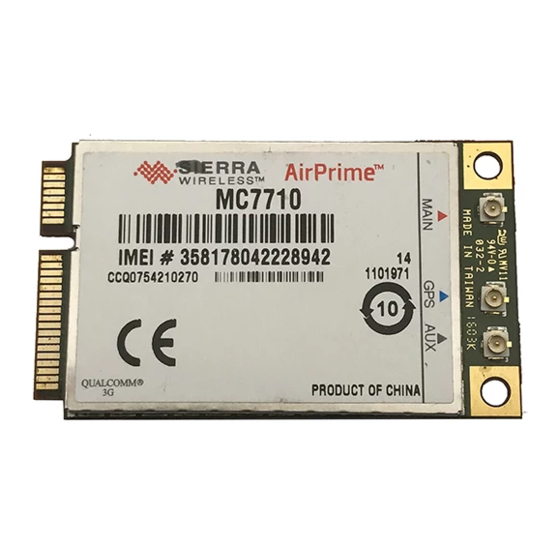
Page 59: Labeling
Figure 8-3: Unit label Note: The displayed label is an example only. The production label will vary by SKU. The MC7710 label is non-removable and contains: • Sierra Wireless logo and product name • IMEI number in Code-128 barcode format •... -
Page 60: Thermal Considerations
Product Technical Specification & Customer Design Guidelines Thermal considerations Embedded modules can generate significant amounts of heat that must be dissipated in the host device for safety and performance reasons. Transmitter Receiver Baseband 1 Baseband 2 Pin 1 Pin 1 Bottom Figure 8-4: Shield locations The amount of thermal dissipation required depends on:... - Page 61 Mechanical and Environmental Specifications Module integration testing When testing your integration design: • Test to your worst case operating environment conditions (temperature and voltage) • Test using worst case operation (transmitter on 100% duty cycle, maximum power) • Monitor temperature at all shield locations. Attach thermocouples to the areas indicated in Figure 8-4 on page 60 (Transmitter, Baseband 1, Receiver,...
- Page 62 Product Technical Specification & Customer Design Guidelines Proprietary and Confidential - Contents subject to change 2400089...
-
Page 63: Regulatory And Industry Approvals
(i.e., have errors) or be totally lost. Although significant delays or losses of data are rare when wireless devices such as the Sierra Wireless modem are used in a normal manner with a well- constructed network, the Sierra Wireless modem should not be used... -
Page 64: Eu Regulatory Conformity
EU regulatory conformity Sierra Wireless hereby declares that the MC7710 modem conforms with all essential requirements of Directive 1999 / 5 / EC, where applicable. The Declaration of Conformity made under Directive 1999 / 5 / EC is available for viewing at the following location in the EU community: Sierra Wireless (UK) Limited... -
Page 65: Antenna Specification
Ant1 and Ant2 Includes mismatch losses, losses in the • matching circuit, and antenna losses, excluding cable loss. Sierra Wireless recommends using • antenna efficiency as the primary parameter for evaluating the antenna system. Peak gain is not a good indication of... - Page 66 Product Technical Specification & Customer Design Guidelines Table A-1: Antenna requirements (Continued) Parameter Requirements Comments < 0.4 on 730–960 MHz band Envelope correlation coefficient between Ant1 < 0.3 on 1800–1990 MHz and and Ant2 2110–2170 MHz bands < 0.2 on 2600–2700 MHz band ...
-
Page 67: Recommended Gps Antenna Specifications
Antenna Specification Recommended GPS antenna specifications Table A-2: GPS standalone antenna requirements Parameter Requirements Comments 1575.42 MHz ±2 MHz • Frequency range minimum 1565–1606 MHz recom- • mended Omni-directional in azimuth • Field of view (FOV) ° ° to +90 in elevation •... - Page 68 Note: Additional testing, including active performance tests, mechanical, and accelerated life tests can be discussed with Sierra Wireless’ engineering services. Contact your Sierra Wireless representative for assistance. Proprietary and Confidential - Contents subject to change...
-
Page 69: Design Checklist
B: Design Checklist This chapter provides a summary of the design considerations mentioned throughout this guide. This includes items relating to the power interface, RF integration, thermal considerations, cabling issues, and so on. Note: This is NOT an exhaustive list of design considerations. It is expected that you will employ good design practices and engineering principles in your integration. - Page 70 Product Technical Specification & Customer Design Guidelines Table B-1: Hardware integration design considerations (Continued) Suggestion Section where discussed Provide ESD protection for the SIM connector at the exposed SIM implementation on page 34 contact point (in particular, the CLK, VCC, IO, and RESET lines). Keep very low capacitance traces on the USIM_DATA and SIM implementation on page 34...
-
Page 71: Testing
Acceptance testing Note: Acceptance testing is typically performed for each shipment received. When you receive a shipment from Sierra Wireless, you should make sure it is suitable before beginning production. From a random sampling of units, test that: •... -
Page 72: Acceptance Test Requirements
The AirPrime embedded module has been certified as described in Regulatory and Industry Approvals on page When you produce a host device with a Sierra Wireless AirPrime embedded module, you must obtain certifications for the final product from appropriate regulatory bodies in the jurisdictions where it will be distributed. -
Page 73: Production Testing
Testing • Factory Mutual (FM Global — www.allendale.com) • Underwriters Laboratories Inc. (www.ul.com) • CDG (CDMA Development Group — www.cdg.org) • GCF (Global Certification Forum — www.globalcertificationforum.org) outside of North America • PTCRB (PCS Type Certification Review Board — www.ptcrb.com) in North America Production testing Note: Production testing typically continues for the life of the product. -
Page 74: Production Test Procedure
4. Test W_DISABLE_N — Turn on the module by letting W_DISABLE_N float (high impedance). 5. Test USB functionality — Check for USB enumeration. · (Windows systems) The Device Manager shows Sierra Wireless items under Ports (COM & LPT). The devices shown depend on the module type. For example: ls / dev / tty / USB* ·... - Page 75 Testing · With one other USB device already connected and assigned to ttyUSB1: (Note: The AT port is the fourth new device — / dev / ttyUSB4.) 6. Make sure your modem is connected and running, and then establish contact with the module: ·...
- Page 76 15. Drive W_DISABLE_N low and confirm that the module powers down: · Windows systems — The Sierra Wireless items under the Ports (COM & LPT) entry in Device Manager disappear as the module powers off. · Linux systems — Enter the command ls / dev / tty / USB* .
-
Page 77: Umts Rf Transmission Path Test
Testing Enter 7. Press twice. Save setup as dfl 8. Use the down-arrow key to select Exit 9. Select UMTS RF transmission path test Note: This procedure segment is performed in Step 12 of the Production test procedure on page Table C-1 contains parameters used in the suggested test procedure that follows. - Page 78 Product Technical Specification & Customer Design Guidelines AT!DASCHAN=<channel> (Set modem channel) · Table C-1 for appropriate <channel> values e. (GSM mode only) AT!DAGSTXFRAME=0, 1, 3000, 0 (Set Tx frame structure.) AT!DASTXON (Turns on the transmit path.) g. (WCDMA mode only) AT!DAWSTXCW=0 (Use a modulated carrier.)...
-
Page 79: Umts Rf Receive Path Test
Testing UMTS RF receive path test Note: This procedure segment is performed in Step 13 of the Production test procedure on page Table C-2 contains parameters used in the suggested test procedure that follows. Table C-2: Test settings — Receive path Bands Mode Test category... - Page 80 Product Technical Specification & Customer Design Guidelines 2. Set up the DUT: AT!ENTERCND (Unlock extended AT command set.) AT!DAFTMACT (Put modem into factory test mode.) AT!DASBAND=<band> (Set frequency band.) · Table C-2 on page 79 for <band> values AT!DASCHAN=<channel> (Set modem channel) ·...
-
Page 81: Lte Rf Receive Path Test
Testing LTE RF receive path test Note: This procedure segment is performed in Step 13 of the Production test procedure on page Table C-3 contains parameters used in the suggested test procedure that follows. Table C-3: Test settings — Receive path Bands Mode Test category... -
Page 82: Gps Standalone Connector Test
Product Technical Specification & Customer Design Guidelines AT!DASCHAN=<channel> (Set modem channel) · Table C-3 on page 81 for <channel> values AT!DALGAVGAGC=<channel>,0 (Get averaged Rx AGC) · Table C-3 on page 81 for <channel> values 3. Test limits — Run ten or more good DUTs through this test procedure to obtain a nominal received power value. -
Page 83: Quality Assurance Testing
Testing 5. (Optional) Turn the signal generator on again, and reduce the level to - !DACGPSCTON 120dBm. Take more readings and use these as a reference for what a marginal / poor signal would be. Note: The response to AT!DACGPSCTON for a good connection should show CtoN within 58 +/- 5dB (preliminary value) and Freq (frequency offset) within 100000 Hz +/- 5000 Hz . -
Page 84: Iot/Operator Testing
Sierra Wireless offers assistance to OEMs with the testing process, if required. Extended AT commands for testing Sierra Wireless provides proprietary AT commands that may help in hardware... - Page 85 Testing Table C-4: Extended AT commands (Continued) Command Description Return an averaged RSSI (Received Signal Strength !DAGGAVGRSSI Indicator) in dBm (GSM mode) Return the raw RSSI (GSM mode) !DAGGRSSIRAW Return GSM mode RF information !DAGINFO Return the RF synthesizer lock state !DAGSLOCK Set the GSM receiver to burst mode !DAGSRXBURST...
- Page 86 Product Technical Specification & Customer Design Guidelines Proprietary and Confidential - Contents subject to change 2400089...
-
Page 87: Packaging
D: Packaging Sierra Wireless AirPrime Mini Cards are shipped in sealed boxes. The standard packaging (see Figure 4-1), contains a single tray with a capacity of 100 modules . (Note that some SKUs may have custom packaging — contact Sierra Wireless for SKU-specific details.) In the standard packaging, Mini Cards are inserted, system connector first, into the bottom portion (T1) of a two-part tray. - Page 88 Product Technical Specification & Customer Design Guidelines Proprietary and Confidential - Contents subject to change 2400089...
-
Page 89: References
(Doc# 2130705) [5] AirCard / AirPrime USB Driver Developer’s Guide (Doc# 2130634) Industry / other documents The following non-Sierra Wireless references are not included in your documentation package: [6] FCC Regulations - Part 15 - Radio Frequency Devices [7] IEC-61000-4-2 level 3 [8] IEC-61000-4-2 level (Electrostatic Discharge Immunity Test) [9] Mobile Station (MS) Conformance Specification;... - Page 90 Product Technical Specification & Customer Design Guidelines [12] JESD22-A114-B [13] JESD22-C101 Proprietary and Confidential - Contents subject to change 2400089...
-
Page 91: Acronyms
F: Acronyms Table F-1: Acronyms and definitions Acronym or term Definition 3rd Generation Partnership Project 3GPP Octagonal Phase Shift Keying 8PSK Automatic Gain Control Assisted GPS A-GPS Application Programming Interface Bit Error Rate — A measure of receive sensitivity Block Error Rate BLER Wireless protocol for data exchange over short distances bluetooth... - Page 92 Product Technical Specification & Customer Design Guidelines Table F-1: Acronyms and definitions (Continued) Acronym or term Definition Distributed Shared Memory Device Under Test Enhanced Data rates for GSM Evolution EDGE Effective (or Equivalent) Isotropic Radiated Power EIRP Electromagnetic Compatibility Electromagnetic Interference Effective Radiated Power Electrostatic Discharge Federal Communications Commission...
- Page 93 Acronyms Table F-1: Acronyms and definitions (Continued) Acronym or term Definition Hertz = 1 cycle / second Industry Canada Intermediate Frequency International Mobile Equipment Identity IMEI Peak current drawn when a device is connected or powered on inrush current Radio Access Technology inter-RAT Interoperability Testing Interim Standard.
- Page 94 Product Technical Specification & Customer Design Guidelines Table F-1: Acronyms and definitions (Continued) Acronym or term Definition Power Amplifier A short, fixed-length block of data, including a header, that is transmitted as a unit packet in a communications network. Printed Circuit Board Personal Communication System A cellular communication infrastructure that uses the 1.9 GHz radio spectrum.
- Page 95 Acronyms Table F-1: Acronyms and definitions (Continued) Acronym or term Definition Single Input Single Output—antenna technology that uses a single antenna at SISO both the transmitter side and the receiver side. Stock Keeping Unit—identifies an inventory item: a unique code, consisting of numbers or letters and numbers, assigned to a product by a retailer for purposes of identification and inventory control.
- Page 96 Product Technical Specification & Customer Design Guidelines Proprietary and Confidential - Contents subject to change 2400089...
- Page 97 Index Numerics block diagram expanded RF, 27 system, 26 3D gain, average bottom view, 58 gain 3D average (GPS), 67 3GPP compliance GSM / GPRS / EDGE, 23 LTE, 23 cable loss UMTS, 23 antenna, maximum, 39 capacitors with SIM, 34 with XIM_DATA / XIM_CLK, 34 carrier/operator...
- Page 98 Product Technical Specification & Customer Design Guidelines grounding connection considerations, 41 EDGE bands supported, 15 overview, 22 frequency band support, 45 bands supported, 15 GSM / GPRS / EDGE connector, required, 18 3GPP compliance, 23 power classes, 22 GERAN compliance, 23 electrical specifications, 25 electrostatic discharge...
- Page 99 Index power example, 37 design checklist, 69 states, 37 handling, 66 output, 25, 35, 37 power-up timing, 53 ramp-up timing, 53 3GPP compliance, 23 state machines, 52 overview, 21 states, module, 51– 53 bands supported, 15 supply, RF interference, 54 bandwidth support, 44 supply, ripple...
- Page 100 Product Technical Specification & Customer Design Guidelines RF bands supported SSS, 16 summary, 15 standalone mode, GPS, 17 GSM, 45 standby DC power consumption, averaged, 49 LTE, 44 state machines, 52 WCDMA, 44 support RF block diagram, expanded, 27 features, 17 RF connector location, 39 testing assistance by Sierra...
- Page 101 Index WCDMA frequency band support, 44 Wireless Disable, 25, 35 vibration specifications, 57 Wireless Disable (GPS), 25 VSWR, 65, 67 Wireless Disable (Main RF), 36 WLAN_LED_N, 35, 37 W_DISABLE_N, 35, 36 WAKE_N, 25, 35 ZIF (Zero Intermediate Frequency), 41 warranty, 17 Rev 6 Mar.13 Proprietary and Confidential - Contents subject to change...
- Page 102 Product Technical Specification & Customer Design Guidelines Proprietary and Confidential - Contents subject to change 2400089...
Need help?
Do you have a question about the AirPrime MC7710 and is the answer not in the manual?
Questions and answers