Hunter Rain-Clik Product Information
Simple, accurate, rugged and reliable rain, freeze, wind, and flow sensors
Hide thumbs
Also See for Rain-Clik:
- Installation manual ,
- Owner's manual & installation instructions (20 pages) ,
- Owner's manual (16 pages)

Subscribe to Our Youtube Channel
Related Manuals for Hunter Rain-Clik


Summary of Contents for Hunter Rain-Clik
- Page 1 P R O D U C T I N F O R M A T I O N Sensors Simple, Accurate, Rugged and Reliable Rain, Freeze, Wind, and Flow Sensors...
-
Page 3: Table Of Contents
TABLE OF CONTENTS Sensor Product Category Overview ......................... 4 Rain Sensors Rain Sensor Product Comparison ........................4 Rain-Clik™ / Wireless Rain-Clik™ ........................ 5 Product Features and Benefits ........................5 Troubleshooting ............................7 Installation and Maintenance ........................8 Wireless Rain-Clik ............................10 Product Features and Benefits ........................ -
Page 4: Sensor Product Category Overview
SENSOR PRODUCT CATEGORY OVERVIEW When you are concerned with water waste, Hunterʼs prevent its future operation until the flow is normal- sensing devices backed by a 5-year warranty need to be ized to the desired level. The device can shut down a part of your irrigation system. -
Page 5: Rain-Clik™ / Wireless Rain-Clik
Dependent on the intensity in routing wire as well as for retrofit applications, the of the rain, the Hunter Rain-Clik will shut down the wireless feature provides a cost effective quick and irrigation system within 2-5 minutes after it begins to clean installation. - Page 6 Unlike other rain sensors that use collection cups, the over a two-hour period. The single hygroscopic disc Rain-Clik does not collect debris, so it does not require that activates the Quick Response™ feature becomes ongoing maintenance or cleaning. And, for those...
-
Page 7: Troubleshooting
If multiple common wires stands up to the environment. The end-user can be as- are used in the system, the Rain-Clik must be tied in to sured of a quality product with a guarantee of depend- the terminus of all the common wires, then connected able operation. -
Page 8: Installation And Maintenance
Rain-Clik from drying will be exposed to unob- soon enough. structed rainfall, but not Once the Rain-Clik is mounted, run the wire to the in the path of sprinkler controller, and fasten it every few feet with wire clips spray. The switch-housing or staples for best results. - Page 9 “SEN” terminal from the Rain-Clik, and secure with a wire nut. (See Fig. 2). Attach the other wire of the Rain-Clik to the “com- Rain-Clik Hunter ICC/Pro-C mon” terminal on the controller. Note: The pump circuit output must be 24 Volts in this situation.
-
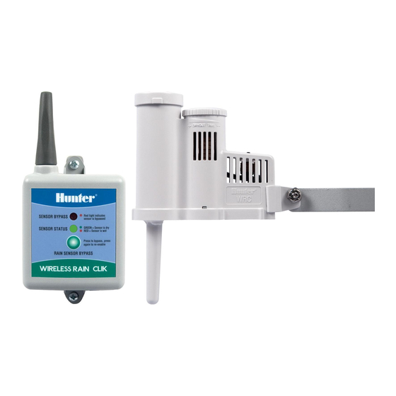
Page 10: Wireless Rain-Clik
Instal- • Hiding the sensor wires that go back to the control- lation of the Wireless Rain-Clik is ideal for instal- ler can sometimes be a difficult, time-consuming lating a rain sensor on an existing landscaped site, and costly process. - Page 11 RAIN SENSOR BYPASS A. Choose a location such as on the side of a building matter). or post. The closer the Wireless Rain-Clik is to the 2. Attach the blue controller, the better reception will be. DO NOT wire to the RS Common Wire EXCEED 300 feet.
-
Page 12: Troubleshooting
System will not come on at all: Each transmitter produced has a unique address A. First, check to see that the Wireless Rain-Clik discs hard-coded into it. A receiver must learn this address are dry and the switch “clicks” on and off freely by to work with that transmitter. -
Page 13: Mini-Clik ® Rain Sensor
Adjustments and Operation There is no required maintenance for the unit. The Operation Check to Verify Correct Wiring Rain-Clik does not have to be removed or covered for “winterizing” purposes. Turn on one zone of the Manually depress the spindle at... -
Page 14: Product Features And Benefits
5-Year Warranty… Mini-Clik-C – Features a Hunter Industries backs up its products ½" female threaded inlet at A full five-year warranty by Hunter communicates to the bottom to accommodate our customers that the Mini-Clik is a rain sensor that conduit. -
Page 15: Installation Instructions
Conductor Wire… be moved for mount- Fast and easy mounting out of sight ing on any angled Hunter supplies wire needed for installation within surface. Loosen the 25 feet of the controller. Whether you pre-install on a locknut and screw... - Page 16 Once the Mini-Clik is mounted, run the wire to the controller, and fasten it every few feet with wire clips Wiring to the Hunter ICC, Pro-C or or staples for best results. If an extension to the wire EC Controller...
- Page 17 Mini-Clik Sensor ® (usually marked “C”) on the controller. Attach the or non-existent. If there is no relay in the circuit, other wire of the Mini-Clik to the common wire one must be added. The wiring for an internal or ®...
-
Page 18: Troubleshooting
System will not shut off even after heavy rainfall: water applied by the system per cycle. A. If a Hunter SRC controller is used, check the dial Basically, if you know the water costs in your area position. If the dial is on the RUN (Bypass Sensor) and how much water is being applied per watering position the controller will disregard sensor. -
Page 19: Replacement Parts
“normally closed” or “normally open” sensor circuits. The unit comes from Hunter with three colored wires attached ready for installation. Depending on what the controller sensor circuitry is, the installer will hook up the green and red wires for “normally closed”... -
Page 20: Freeze Sensor
WIND-CLIK to slow down to in order to reset the switch. The Note: To add Bypass Switch Box to any non-Hunter controller Wind-Clik allows the user to adjust a reset speed be- installation, specify BPSW with sensor. Bypass switch function tween 8 and 24 mph with a turn of the side adjustment. -
Page 21: Product Features And Benefits
5-Year Warranty… peratures approach freezing Hunter Industries backs up its products (example: to protect vegetation A full five-year warranty by Hunter communicates from a damaging freeze). to our customers that the Freeze-Clik is an irrigation Note: The Freeze-Clik is not designed for crop protection sensor that stands up to the environment. - Page 22 3. Connect the valve common to the RS terminal. The Freeze-Clik is preset and is not adjustable. It will break the common ground circuit, thereby keeping Wiring to the Hunter ICC, Pro-C and the sprinkler system from operating at, or below, 3˚C EC Controller (37˚F).
-
Page 23: Mini-Weather Station
OPTION FREEZE-CLIK REV = Reverse Switching Easy to Install on Any Automatic Note: To add Bypass Switch Box to any non-Hunter controller Irrigation System… installation, specify BPSW with sensor. Bypass switch function is standard in all Hunter controllers. Versatile enough to meet your particular needs The Mini-Weather Station is designed to install directly to a “normally closed”... -
Page 24: Weather Sensor Options
Rain Sensors of the sensor that leads to the solenoid valves (Fig. 1). Note: To add Bypass Switch Box to any non-Hunter controller installation, specify BPSW with sensor. Bypass switch function is If possible, make the wire connec- standard in all Hunter controllers. -
Page 25: Flow Sensors
Model: SG-MC receive the benefits of monitoring flow are very costly, the relative low cost of the Hunter Flow-Clik fits into any site's budget. At a fraction of the cost, the Hunter Flow-Clik provides the many benefits associated with FLOW-CLIK™... - Page 26 The Hunter Flow Sensor Interface Box allows the Simple to add on to a new or existing installation Hunter Flow-Clik to function with all of the Hunter The Flow-Clik™ can be installed simply and easily to controllers and makes the Flow-Clik compatible with any standard 24-volt irrigation control system.
- Page 27 An advantage Customized Calibration for Precise of the Hunter Flow-Clik is that it can be System Control… installed up to a maximum distance of 1000 feet from the interface when...
-
Page 28: Flow-Clik System Overview
FLOW-CLIK™ SYSTEM OVERVIEW Flow-Clik™ System Overview 6:00 AM – Valve 3 is activated and after a 20 sec- ond delay a “high flow” condition is sensed by Illustrative Example the Flow-Clik and the system is interrupted for In this illustrative example of a small commercial site, 10 minutes. -
Page 29: Installation Instructions
Flow-Clik Sensor ™ enabling the valve to continue to irrigate for its Note: For maximum protection against overflow conditio- ns, it is required that a master valve be installed. prescribed time. Post 6:20 AM – For the balance of the day (provided Minimum 5 x pipe that Zone 3 is not scheduled to operate again), flow diameter from nearest... - Page 30 Interface Box. A lock is also provided to prevent Wiring the Interface Box to the Controller unauthorized changes in Flow-Clik™ Hunter controllers have provisions for sensor installa- settings. There are two mounting tabs tions that allow for easy wiring of the Flow-Clik to the on the top and bottom of the Interface controller.
- Page 31 flow condition. The Flow-Clik™ can be wired to a controller al- The more balanced the irrigation system is designed, ready using another Hunter sensor (i.e. Rain-Clik™, the more protection will be provided by the Flow-Clik. Wind-Clik , Freeze-Clik , etc.) or other micro-switch...
- Page 32 2. Identify the model of sprinkler and its associated will be yellow. After a 10 second period of “learning” it nozzle for each valve. Valve 4 has Hunter I-20 will begin to monitor system flow. rotors that have various nozzles based on the dis- If you already know the highest flow zone within...
- Page 33 The Flow-Clik monitors for a high 3. Start a manual cycle on the controller beginning flow condition, shutting down the sys- with the first zone (for Hunter controllers, use the tem or individual zone when overflow One Touch Manual Advance feature).
-
Page 34: Troubleshooting Guide
INSTALLATION INSTRUCTIONS (continued) Sensor Bypass If the sensor experiences an overflow condition, the system status indicator will identify the overflow, but The Sensor Bypass setting allows the user to manu- the interface box will continue to allow the controller ally override the Flow-Clik™ sensor. This is helpful to operate. -
Page 35: Specifications
100 sec. User adjustable set point √ √ Programmable automatic controller reset 2-60 min. manual reset Fast, easy hookup on any Hunter controller √ Easily adaptable to other manufacterrs controllers Needs separate relay control Separate transmitter, √ power supply and software... -
Page 36: Sensors Training Manual Quiz
15. The mini weather station that incorporates a rain sensor, from operating for a minimum of _____ to a maximum wind sensor and a freeze sensor in one unit is a Hunter of _____ after the rain stops falling. ________ model. -
Page 37: Quiz Answers
Sensors Quiz QUIZ ANSWERS... - Page 40 Hunter Industries Incorporated • The Irrigation Innovators © 2005 Hunter Industries Incorporated 1940 Diamond Street • San Marcos, California 92078 • TEL: (1) 760-744-5240 • FAX: (1) 760-744-7461 www.HunterIndustries.com P/N 700676 LIT-293 4/05...
Need help?
Do you have a question about the Rain-Clik and is the answer not in the manual?
Questions and answers