Hunter WIRELESS RAIN-CLIK Installation Card
Hide thumbs
Also See for WIRELESS RAIN-CLIK:
- Installation manual ,
- Product information (40 pages) ,
- Owner's manual & installation instructions (20 pages)
Advertisement
Quick Links
WIRELESS RAIN-CLIK
INSTALLATION CARD
Introduction
The Wireless Rain-Clik acts as a switch to break the circuit to the
solenoid valves of the irrigation system when a rain event occurs.
This allows the timer to advance as scheduled, but keeps the valves
from opening the water flow. Once the Wireless Rain-Clik has dried
sufficiently, the switch closes again to allow for normal operation.
The Wireless Rain/Freeze-Clik includes a freeze sensor that is
designed to keep the system from operating at or below 3°C. At higher
temperatures, it will close the circuit for normal sprinkler operation.
Mounting
Standard Mounting
Using the screws provided, mount the Wireless Rain-Clik on any
surface where it will be exposed to unobstructed rainfall, but away
from sprinkler spray. The switch housing portion must be upright (as
pictured), but the swivel-bracket can be moved for mounting on any
angled surface. Loosen the locknut and screw before swiveling the
bracket, and then re-tighten.
Gutter Mount (SGM Sold Separately)
The sensor gutter mount can be purchased as an optional accessory for
your Wireless Rain-Clik (order P/N SGM). The SGM allows the Wireless
Rain-Clik to be mounted directly to the side of a gutter. To install your
Wireless Rain-Clik on a gutter, remove the screw, nut, and standard
metal extension arm, and reinstall the screw and gutter mount. Position
the mount on gutter edge and twist the thumbscrew to secure it.
Helpful Hints for Mounting
A. Choose a location such as on the side of a building or post. The
closer the Wireless Rain-Clik is to the controller, the better reception
will be. Do not exceed 61 m.
B. Correct placement of the Wireless Rain/Freeze-Clik model is
important for accurate temperature sensing. Choose a location out
of direct sunlight.
C. As described in the "Operation" section of this manual, reset rate
refers to the time it takes the
Wireless Rain-Clik to dry out
sufficiently for the sprinkler
system to come back on.
The mounting location will
affect this rate and should
be taken into consideration
during extreme conditions.
For example, mounting
the Wireless Rain-Clik on a
very sunny, southern end
of a building may cause the
Wireless Rain-Clik to dry out
sooner than desired. Similarly,
mounting on the northern
end of a building with
constant shade may keep the
Wireless Rain-Clik from drying soon enough.
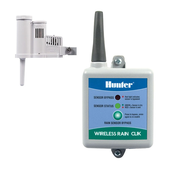
Sensor
•
There is nothing to set up with this unit after installation.
•
The unit can be tested standalone as follows: Press and hold
the post on the quick response section. Within three seconds of
pressing and holding this post down, the LED protruding from the
potting should blink once. Release the post; within three seconds
the LED should blink once again (Figure 1).
& RAIN/FREEZE-CLIK
TM
Standard Mount
Gutter Mount (Optional)
|For more information visit Thelandscapestore.com.au | (02) 9161 3939 |
SENSORS
TM
Receiver
•
Using the hardware included,
mount the receiver to the wall (use
included wall anchors if needed).
Put the rubber cover/gasket
under the unit when attaching it
outdoors.
Wiring to Your
Irrigation System
WARNING! This unit is designed to be installed in conjunction with
24 VAC circuits only. Do not use with 110 or 220 VAC circuits.
Receiver Installation, Hunter Controllers (Figure 2)
1.
Attach the two yellow wires to the AC terminals of the controller
(polarity does not matter).
2. Attach the blue wire to one SEN
terminal and the white wire to
the other SEN terminal.
3. For Hydrawise® controllers,
attach the white wire to the
SEN COM terminal and the
blue wire to SEN-1 or SEN-2
terminals. Sensor is configured
in the Hydrawise software under
sensors setting.
4. Leave the orange wire
unconnected.
Receiver Installation, Other
Controllers: Normally Closed Sensor
Applications (Figure 3)
1.
Attach the two yellow wires to the
AC terminals of the controllers
(polarity does not matter).
2. To attach the receiver to this type
of controller, attach the blue wire
and the white wire to the sensor
terminals of the controller, or
in-line with the valve common.
3. Leave the orange wire disconnected.
Normally Open Sensor Applications
1.
Some controllers on the market require a normally open rain sensor.
To attach the receiver to this type of controller, attach the blue wire
and the orange wire to the controller's sensor input.
Setting the Transmitter Address at the Receiver
Units purchased as a kit will already have their address learned, so
no addressing is necessary. However, if the receiver or transmitter is
replaced, you must reset the address.
Each transmitter produced has a unique address hard-coded into it.
A receiver must learn this address to work with that transmitter. This
step will only be necessary if transmitters and receivers are purchased
separately.
1.
Prior to applying power (yellow wires) to the receiver, press and hold
the push button on the receiver.
2. With the push button held, apply power to the receiver. The
receiver's "sensor status" LED should light up yellow, which
indicates the receiver is ready to learn an address.
Manually depress the
spindle at the top of
the rain sensor
Figure 1
Hunter
Controllers
Wireless
C
Receiver
P/MV
B
SEN
W
SEN
TEST
SENSOR BYPASS
Red light indicates
sensor is bypassed
REM
SENSOR STATUS
GREEN = Sensor is dry
RED = Sensor is wet
Y
Press to bypass, press
again to re-enable
AC
RAIN SENSOR BYPASS
Y
AC
G
O
Figure 2
Wireless
Receiver
Other
Controllers
SENSOR BYPASS
Red light indicates
sensor is bypassed
C
P/MV
AC AC
SENSOR STATUS
GREEN = Sensor is dry
RED = Sensor is wet
Press to bypass, press
again to re-enable
RAIN SENSOR BYPASS
W
Common wire
to all valves
B
Y
Y
Used for normally
O
open sensor
Figure 3
applications
Advertisement

Related Manuals for Hunter WIRELESS RAIN-CLIK


Summary of Contents for Hunter WIRELESS RAIN-CLIK
- Page 1 • Using the hardware included, spindle at the top of The Wireless Rain-Clik acts as a switch to break the circuit to the the rain sensor mount the receiver to the wall (use solenoid valves of the irrigation system when a rain event occurs.
- Page 2 Pressing the “BYPASS” button again will cause the RED BYPASS LED to turn off, which re-enables the sensor. hunterindustries.com/support/sensors/rain-clik Need help? Visit © 2020 Hunter Industries Inc. Hunter, the Hunter logo, and all other trademarks are property of 23-461 C EM 5/20 Hunter Industries, registered in the U.S.
Need help?
Do you have a question about the WIRELESS RAIN-CLIK and is the answer not in the manual?
Questions and answers