Table of Contents
Advertisement
Programmable
Thermostats
2020NC
2220NC
1 Specifications
2 About Your Thermostat
3 Installation
4 System Testing
5 Setting User Options
Warning
Attention
Read all instructions before proceeding.
This thermostat requires 24 Volt AC Power or two (2) properly installed "AA"
Alkaline batteries for proper operation. When connecting 24 Volt AC Power
the batteries may be installed as a backup.
components of the system shall conform to Class II Circuits per NEC code.
For use only as described in this manual. Any other use
will void warranty.
1 Specifications
This thermostat is compatible with:
• Single stage heat / cool conventional and heat pump systems
• Conventional systems up to 2 heat / 1 cool (2220NC only)
• Single compressor heat pump systems with an auxiliary heat stage (2220NC)
• 250 – 750 millivolt heat only systems
Electrical and control specifications:
• Electrical Rating: 24 Volt AC
• 1 amp maximum load per terminal
• AC Power: 18 – 30 Volts AC
• DC Power: 3.0 Volt DC (2 "AA" Alkaline Batteries Included)
• Control Range: 45° – 90° F (7° – 32° C)
• Temperature Accuracy: +/- 1° F (+/- .5° C)
Terminations
• 2020NC – Rc, Rh, O, B, Y1, W1, G, C
• 2220NC – Rc, Rh, O, B, Y1, E/W1, G, W2, C
Single Stage Heat / Cool
Conventional and Heat Pump
Up to 2 Heat / 1 Cool Conventional
Up to 2 Heat / 1 Cool Heat Pump
Model number is located on back of thermostat
6 Setting Your Program Schedule
7 Operating Your Thermostat
8 Additional Operation Features
9 Thermostat Maintenance
Turn off power to the heating or cooling
equipment before installation.
For installation by experienced service
technicians only.
®
Detailed
User Guide
Thermostat installation and all
2020NCW-100-05
Advertisement
Table of Contents

Related Manuals for Braeburn 2020NC


Summary of Contents for Braeburn 2020NC
- Page 1 • Control Range: 45° – 90° F (7° – 32° C) • Temperature Accuracy: +/- 1° F (+/- .5° C) Terminations • 2020NC – Rc, Rh, O, B, Y1, W1, G, C 2020NCW-100-05 • 2220NC – Rc, Rh, O, B, Y1, E/W1, G, W2, C...
-
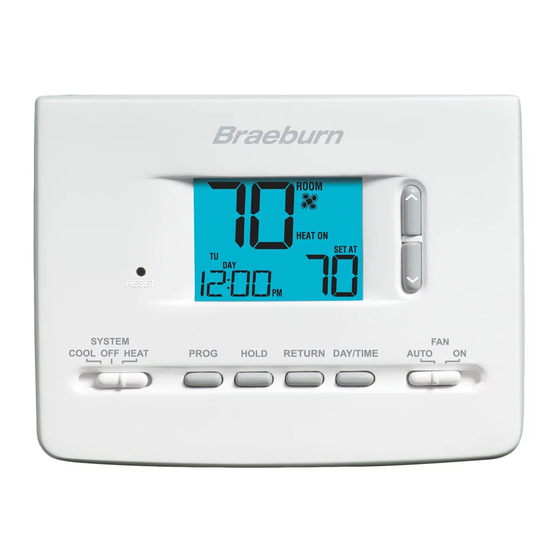
Page 2: About Your Thermostat
2 About Your Thermostat Room Temperature ... Displays the current room temperature Day of Week ...... Displays the current day of week Program Event Indicator .. Indicates the current program event Time of Day ....... Displays the current time of day Low Battery Indicator .. -
Page 3: Installation
Avoid installation in locations where the thermostat can be affected by drafts, dead air spots, hot or cold air ducts, sunlight, appliances, concealed pipes, chimneys and outside walls. Install your new Braeburn thermostat in 5 basic steps: 1 Install the Sub-Base 2 Provide Power... -
Page 4: Connect Your Wires
Provide Power 24VAC Power Terminal (C) • For 24 Volt AC power, you must connect the common side of the trans- former to the C terminal on the thermostat sub-base. • For primary or back-up power, insert the 2 supplied “AA” type alkaline batteries into the battery compartment located in the rear housing of the thermostat. - Page 5 Conventional Systems Typical Wiring Configurations NOTE: The “Installer Switch” option will be configured in the next step. Heat Only or Millivolt Set Installer Switch to CONV Rh Power Connection W Heat Relay (appears as W1/E on 2220NC) Fan Relay [note 4] 24 Volt AC Transformer Common [note 1] 1 HEAT / 1 COOL Single or Dual Transformer Set Installer Switch to CONV...
- Page 6 Heat Pump Systems Typical Wiring Configurations NOTE: The “Installer Switch” option will be configured in the next step. 1 HEAT / 1 COOL - No Auxiliary Heat Set Installer Switch to HP 24 Volt AC Power Connected to Rh with supplied Jumper Wire O or B Changeover Valve [note 2] Compressor Relay Fan Relay...
-
Page 7: Attach Thermostat To Sub-Base
NOTE: Installer switches are located on the back of the thermostat. The reset button must be pressed after making any changes to these switches. Attach Thermostat to Sub-Base 1. Line up the thermostat body with the sub-base. 2. Carefully push the thermostat body against the sub-base until it snaps into place. -
Page 8: Setting User Options
5 Setting User Options Advanced User Options User options allow you to customize some of your thermostat’s features. Most users will not need to make any changes to the settings in this section. To enter the User Options menu, hold down the RETURN button for approximately 3 seconds until the screen changes and displays the first User Option. -
Page 9: Setting Your Program Schedule
Extended Hold Period* (User Option 4) The Extended Hold Period lets you select the period your thermostat will hold the temperature when the HOLD mode is activated (See “Temperature Adjustment”). When LNG is selected the thermostat will hold your temperature indefinitely. When 24HR is selected, the thermostat will hold your temperature for 24 hours and then return to the current program at that time. -
Page 10: Energy Saving Programs
NOTE: If this thermostat was set in the Installer Settings to be non-programmable, then you cannot set a user program. If you press the PROG HOLD buttons, the word “NO” will appear in the display, indicating there is no program present. See section 5, “Setting User Options”... - Page 11 Programming a 7 Day Schedule The 7 day programming mode gives you the option to program individual days (1 day at a time) or to use SpeedSet and program the entire week (all 7 days) with a 4 event program schedule. Setting All 7 Days at Once (SpeedSet ®...
-
Page 12: Operating Your Thermostat
Programming a 5-2 Day Schedule The 5-2 day programming mode allows you to program Monday - Friday with one 4 event schedule and then allows you to change Saturday and Sunday with a different 4 event schedule. 1. Press the PROG button. -
Page 13: Temperature Adjustment
Setting the Fan Control Mode The Fan Control has 2 modes of operation – AUTO and ON. The mode can be selected by moving the FAN switch to the appropriate position. AUTO The system fan will run only when your heating or cooling system is running The system fan stays on Temperature Adjustment... -
Page 14: Additional Operation Features
8 Additional Operation Features Compressor Protection This thermostat includes an automatic compressor protection delay to help avoid potential damage to your system from short cycling. This feature activates a short delay after turning off the system compressor. 9 Thermostat Maintenance Changing the Batteries Depending on your particular installation, this thermostat may be equipped with two (2) “AA”... -
Page 15: Limited Warranty
2215 Cornell Avenue Montgomery, IL 60538 Braeburn Systems LLC 2215 Cornell Avenue • Montgomery, IL 60538 Technical Assistance: www.braeburnonline.com Call us toll-free: 866-268-5599 (U.S.) 630-844-1968 (Outside the U.S.) 2020NCW-100-05 ©2018 Braeburn Systems LLC • All Rights Reserved. Made in China.
Need help?
Do you have a question about the 2020NC and is the answer not in the manual?
Questions and answers
Replaced batteries and now the screen is blank. Can’t locate troubleshooting instructions. Help!
If the screen is blank after replacing the batteries on the Braeburn 2020NC thermostat, possible reasons include:
1. Incorrect Battery Installation – Ensure the batteries are inserted with the correct (+) and (-) orientation.
2. Dead or Weak Batteries – Try using a fresh set of AA batteries.
3. Loose Thermostat Connection – Make sure the thermostat body is securely pushed back onto the base.
4. System Reset Needed – The thermostat may need a reset after battery replacement.
If the issue persists, professional assistance may be required.
This answer is automatically generated
After a factory reset thermostat, 2020nc will not allow temperature to adjust in both Cool andHeat mode to anything above 32 degrees. All other programming mode work as per the user manual. Now what? Thank you.!