Table of Contents
Advertisement
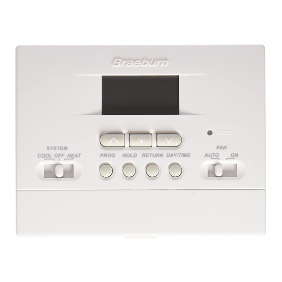
MODEL
2000NC
USER MANUAL
Compatible with low voltage single stage gas, oil
or electric heating or cooling systems, including
single stage heat pumps. This thermostat can
also be used on 250mv to 750mv millivolt heating
only systems. Do not use this thermostat on
applications with voltages above 30 Volts AC.
READ ALL INSTRUCTIONS BEFORE PROCEEDING
CONTENTS
SPECIFICATIONS
1
INSTALLATION
2
TESTING YOUR NEW THERMOSTAT
3
PROGRAMMING
4
WARNING!
Important Safety Information
• Always turn off power to the air conditioning or heating system prior to installing,
removing, cleaning or servicing thermostat.
• Read this manual thoroughly prior to installing, programming or operating
this thermostat.
• This thermostat is designed for use with a 24 Volt-AC low voltage single stage
gas, oil or electric heating or cooling systems.
• Do not use this thermostat on applications with voltages above 30 Volts AC.
• This thermostat requires two (2) properly installed "AA" alkaline batteries to
provide power for the thermostat to properly control the system operation.
• Wiring must conform to all building codes and ordinances as required by local and
national code authorities having jurisdiction.
• Do not short (or jumper) across terminals on the gas valve or at the heating or
cooling system control board to test the thermostat installation. This could
damage the thermostat and void the warranty.
• Do not select COOL mode of operation if the outside temperature is below 50˚ F
(10˚ C). This could possibly damage the controlled cooling system and may cause
personal injury.
• This thermostat should only be used as described in this manual. Any other use is
not recommended and will void the warranty.
®
Builder Series
5-2 Day Programmable
Single Stage Heat/Cool
Digital Thermostat
ADDITIONAL OPERATION FEATURES
5
TROUBLESHOOTING
6
WIRING DIAGRAMS
7
1
SPECIFICATIONS
• Electrical Rating: 24 Volt AC (18-30 Volt AC)
1 amp maximum load per terminal
2 amp total maximum load (all terminals)
• Control Range: 45˚ - 90˚ F (7˚ - 32˚ C)
• Accuracy: +/- 1˚ F (+/- .5˚ C)
• DC Power: 3.0 Volt DC (2 AA Alkaline batteries included)
• Compatibility: Compatible with low voltage single stage gas, oil or electric
heating or cooling systems, including single stage heat pumps. This thermostat
can also be used on 250mv to 750mv millivolt heating only systems.
• Terminations: Rc, Rh, O/B, Y, W, G
2
INSTALLATION
Replacing Existing Thermostat
2.1
1. Always turn off power to the air conditioning or heating system prior to
removing existing thermostat.
2. Remove the cover of your old thermostat and locate the wire terminals.
Do not remove wires from terminals yet.
3. Using small pieces of masking tape, label wires prior to removal from terminals.
Use the chart below to determine the new terminal designations for your
new thermostat.
Old Terminal from
New Terminal for
Existing Thermostat
New Thermostat
V or Rc
Rc
M, 4, Rh, or R
Rh
B or O
O/B
Y
Y
H, W or 4
W
G or F
G
C
None-Cap the wire
4. After labeling and removing all wires from terminals, unscrew the existing
thermostat sub-base from wall. Be sure to secure wires to prevent them from
slipping back into the hole in the wall.
NOTE:
This thermostat is designed for use with a 24 Volt AC low voltage single
stage gas, oil or electric heating or cooling systems, including single stage heat
pumps. This thermostat can also be used on 250mv to 750mv millivolt heating only
systems. Do not use this thermostat on applications with voltages above 30 Volts AC.
Installing Your New Thermostat
2.2
NOTE:
If you are installing this thermostat in a new installation be sure to locate
the thermostat 4 to 5 feet above the floor in accordance with applicable building
codes. Be sure to install the thermostat in a location that provides good airflow
characteristics and avoid areas behind doors, near corners, air vents, direct sunlight
or near any heat generating device. Installation in any of these areas could impact
thermostat performance.
1. Always turn off power to the air conditioning or heating system prior to installing
your new thermostat.
2. Place system switch on front of thermostat to the OFF position.
3. Place fan control switch on front of thermostat to the AUTO position.
4. Remove front of thermostat body from sub-base by pressing release latch on bottom
of front body.
5. Place the thermostat sub-base against wall in the desired thermostat location.
Terminal Description
Cooling Transformer
Heating Transformer
Reversing Valve (Cooling or Heating)
Cooling Control
Heating Control
Fan Control
24 Volt AC, Transformer Common
1
Advertisement
Table of Contents
Troubleshooting

Related Manuals for Braeburn 2000NC


Summary of Contents for Braeburn 2000NC
-
Page 1: Specifications
2 amp total maximum load (all terminals) MODEL 5-2 Day Programmable • Control Range: 45˚ - 90˚ F (7˚ - 32˚ C) 2000NC • Accuracy: +/- 1˚ F (+/- .5˚ C) Single Stage Heat/Cool • DC Power: 3.0 Volt DC (2 AA Alkaline batteries included) Digital Thermostat •... - Page 2 TESTING YOUR INSTALLATION NEW THERMOSTAT cont. NOTE: 6. Guide thermostat wires through center hole in sub-base. Continue to hold sub-base Test your thermostat prior to programming any user settings. Pressing the against wall. RESET button will erase any user entries for time of day, day of week, option settings 7.
- Page 3 PROGRAMMING PROGRAMMING cont. cont. 2. Press the button to set the current hour. Setting Filter Check Monitor (see also section 5.7) 4.3.3 3. Press the DAY/TIME button again, the minute The default setting is 0 days (Filter monitor disabled). portion of the time will flash. 4.
- Page 4 ADDITIONAL OPERATION FEATURES PROGRAMMING cont. cont. Temporary Program Override cont. Entering Your Program 4.4.2 2. The display will return to normal operating mode after 15 seconds or you can press 1. Place the system switch in the HEAT mode of operation. the RETURN button.
-
Page 5: Troubleshooting
ADDITIONAL TROUBLESHOOTING OPERATION FEATURES cont. Low Battery Detection and Replacement cont. SYMPTOM POTENTIAL SOLUTION 1. Locate the battery compartment door. Thermostat does not Check to see if OFF is shown in display. This indicates that the 2. Gently remove the two "AA" alkaline batteries located in the battery compartment. turn on heating or system is turned off at the thermostat. -
Page 6: Wiring Diagrams
TROUBLESHOOTING TROUBLESHOOTING cont. cont. SYMPTOM POTENTIAL SOLUTION SYMPTOM POTENTIAL SOLUTION Thermostat will not This is above the normal thermostat temperature setting range Low battery indicator is Replace batteries immediately to maintain proper system allow me to program of 45˚ to 90˚ F (7˚ to 32˚ C). shown in thermostat operation. - Page 7 Braeburn installation and operating instructions. Braeburn Systems LLC agrees to repair or replace at its option any Braeburn thermostat under warranty provided it is returned postage prepaid to our warranty facility in a padded carton within...
Need help?
Do you have a question about the 2000NC and is the answer not in the manual?
Questions and answers