
Related Manuals for Thermo Scientific SGD-O


Summary of Contents for Thermo Scientific SGD-O
- Page 1 SGD-O Non-Contacting Density Gauge For Fracturing & Cementing User Guide P/N 717910 Revision D Part of Thermo Fisher Scientific...
- Page 3 SGD-O Non-Contacting Density Gauge For Fracturing & Cementing User Guide P/N 717910 Revision D...
- Page 5 © 2012 Thermo Fisher Scientific Inc. All rights reserved. All trademarks are the property of Thermo Fisher Scientific Inc. and its subsidiaries. Thermo Fisher Scientific Inc. (Thermo Fisher) makes every effort to ensure the accuracy and completeness of this manual. However, we cannot be responsible for errors, omissions, or any loss of data as the result of errors or omissions.
- Page 6 This page intentionally left blank.
- Page 7 Revision History Revision Level Date Comments 10-2007 Initial release (ERO 5984). 04-2008 Revised per ECO 6268. 04-2008 Revised per ECO 6298. 01-2012 Revised per ECO 7896. Thermo Fisher Scientific SGD-O User Guide...
- Page 8 This page intentionally left blank.
-
Page 9: Table Of Contents
Post Calibration - Setup at the Job Site ............5-1 General ....................5-1 Procedure .................... 5-1 Chapter 6 The Current Output .................... 6-1 Hold the Current Output ..............6-1 Clear All Holds ................... 6-2 Check the Input Signal ............... 6-2 Thermo Fisher Scientific SGD-O User Guide... - Page 10 Appendix D Gauge Calibration Records ................D-1 Appendix E Commonly Used Parameter & Command DACs .......... E-1 Toxic & Hazardous Substances Tables ............F-1 Appendix F Appendix G Related Technical Bulletins ................G-1 viii SGD-O User Guide Thermo Fisher Scientific...
-
Page 11: Safety Information
The triangular icon displayed with a warning may contain a lightning bolt or the radiation symbol, depending on the type of hazard. Thermo Fisher Scientific SGD-O User Guide... - Page 12 Note Notes emphasize important or essential information or a statement of company policy regarding an operating procedure, practice, condition, etc. SGD-O User Guide Thermo Fisher Scientific...
-
Page 13: Chapter 1 Product Overview
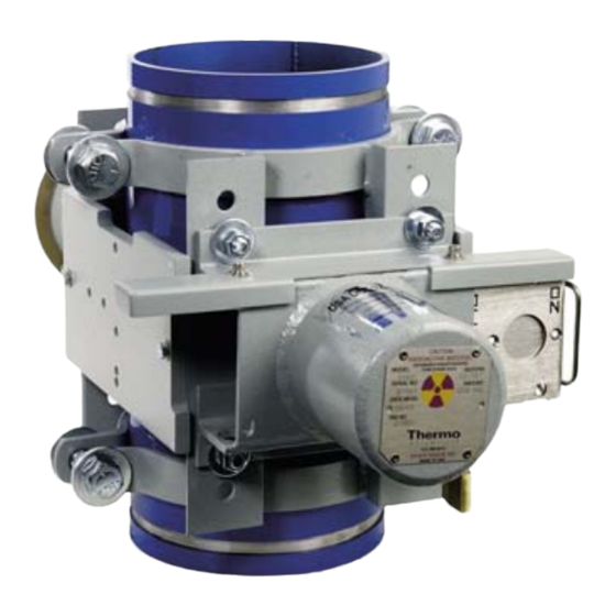
Chapter 1 Product Overview Introduction The Thermo Scientific SGD-O system consists of a radiation source in a lead-filled housing, an ion chamber detector with an amplifier, and the SGD-O transmitter. The transmitter processes the detector signal to provide a signal output proportional to the density of the slurry, the mass of solids added per volume of carrier, or both. - Page 14 Product Overview Introduction Figure 1–2. Example of a shutterless unit installed on a high pressure pipe Figure 1–3. Example of a unit with shutter (low pressure application) SGD-O User Guide Thermo Fisher Scientific...
-
Page 15: The Gamma Source
Regulations for the NRC, U.S. Department of Transportation, and the Canadian Nuclear Safety Commission are continuously being updated; contact Thermo Fisher Scientific for information on proper source disposal. Thermo Fisher Scientific SGD-O User Guide... -
Page 16: The Detector
The Transmitter The SGD-O transmitter is a microprocessor-based system that processes the signal from the detector (0–10 Vdc) to provide an output signal (4–20 mA) representing the amount of solids (proppant) added per volume unit of carrier and/or the bulk density of the slurry. -
Page 17: Inputs & Outputs
Two optional relay outputs can be provided on each I/O board. Note If the detector will be connected directly to customer equipment (i.e. the SGD-O transmitter will not be used), the detector output is 0 to 10 Vdc. Thermo Fisher Scientific... -
Page 18: Required Documentation
Required In addition to this guide, the following documents must be read and understood by all persons installing, using, or maintaining this equipment: Documentation SGD-O Installation Guide (p/n 717913) Gamma Radiation Safety Guide (p/n 717904) SGD-O User Guide... -
Page 19: Chapter 2 Getting Started
Chapter 2 Getting Started Powering the There are three input power options for the SGD-O transmitter: Transmitter 12 Vdc version (standard) ● 24 Vdc (optional) ● 115/230 Vac (optional) ● The transmitter power cable is configured to operate the 12 Vdc version only. -
Page 20: Changing Or Viewing Parameters
In this example, force the current output to 20 mA. The command code is 5. 1. Press: EXIT SETUP, 5, down arrow. 2. The display shows two options. Press the left arrow to reject the command or the right arrow to execute it. SGD-O User Guide Thermo Fisher Scientific... -
Page 21: Detector Setup & Pre-Calibration
± 0.5 Vdc of specified voltage. If one or both of the voltages are incorrect or not there at all, either the transmitter to detector cable is bad or the transmitter is not outputting the ±15 Vdc properly. Thermo Fisher Scientific SGD-O User Guide... - Page 22 Note If the detector output is above 8.0 Vdc, the pipe ID is 6 inches or smaller, and the measurement range is under 10 PPA, it is acceptable to use the voltage and continue to the calibration procedure in Chapter SGD-O User Guide Thermo Fisher Scientific...
-
Page 23: Chapter 4 Gauge Calibration
For optimum performance, calibrate the gauge exactly as described below. It is assumed that the gauge has been installed properly, the shutter is open (if applicable), the pipe is empty of any fluid, and that the SGD-O transmitter is being used. - Page 24 9. Reset the CAL/REF ratio to the default value of 1.000 (DAC 086003). 10. Standardize the gauge on water (DAC 121). This will set the standardization value (water value) that will be used to calculate the ZnCl calibration value. SGD-O User Guide Thermo Fisher Scientific...
- Page 25 16. Recall the density slope correction factor (DAC 049003). Record this value. 17. Recall the carrier specific gravity (DAC 085003). Record this value. Note The values recorded in steps 16 and 17 are required for troubleshooting purposes. Keep these values handy. Thermo Fisher Scientific SGD-O User Guide...
- Page 26 20. The displayed density should then be 1.000 g/ml. The gauge is now calibrated for use of water as the carrier. Note This calibration will be valid as long as the detector is not moved or removed from the housing. SGD-O User Guide Thermo Fisher Scientific...
-
Page 27: Post Calibration - Setup At The Job Site
Chapter 4. Procedure Once the SGD-O gauge is in service, one more operation is necessary for proper indication of the Pounds of Sand Added and the Pounds per Gallon indications of the gauge. Note Reference Chapter 2 for instructions on how to use a DAC. - Page 28 Sand Added and the Pounds per Gallon indications will be correct. When the job is finished, return the carrier density to its original value (DAC 085003). To prepare for the next job, perform a standardization on a pipe full of clean water (DAC 121). SGD-O User Guide Thermo Fisher Scientific...
-
Page 29: The Current Output
Note The initial value in this formula is the measured value of the 20 mA output when the correction factor is equal to 1.0. 3. Hold the current output at 12 mA (DAC 2). Thermo Fisher Scientific SGD-O User Guide... -
Page 30: Clear All Holds
The output of the detector (input to the transmitter) is a voltage signal 0–10 Vdc maximum. Read the signal (DAC 112003). The value is Signal displayed in scientific notation and represents a range of 0 to 10 volts with the numbers 0 to 6.554E4 (65540). SGD-O User Guide Thermo Fisher Scientific... -
Page 31: Adjusting The Gain Settings
Adjusting the Gain Settings Overview Users of the SGD-O density gauge often move the detector assembly from application to application. Among these different applications are variations in sizes and schedules of pipes, as well as activity and ages of radioactive sources. - Page 32 A 220 pF capacitor will make the gain higher and a 470 pF capacitor will make the gain lower. If you are having trouble getting the gain either high enough or low enough, check the value of C13. SGD-O User Guide Thermo Fisher Scientific...
-
Page 33: Gain Control Settings
220, 330, or 470 pF 2X or 3X Gain Control Figure 7–2 shows how the jumpers and resistors work together to control the gain of the AR1 op-amp. Settings Figure 7–2. Gain control of the AR1 op-amp Thermo Fisher Scientific SGD-O User Guide... - Page 34 W2 jumper + W3 jumper + This leaves the W5 leg at 49.9K and puts R36 R36 changed to 49.9 kohm and R37 in parallel, changing the current to the op-amp. SGD-O User Guide Thermo Fisher Scientific...
- Page 35 R36 will change R36 to 4.12 kohm. Everything else remains at default values. W2 jumper + W3 jumper Everything else remains at default values. Figure 7–3. C13 in the control circuit of the FSU detector Thermo Fisher Scientific SGD-O User Guide...
- Page 36 This page intentionally left blank.
-
Page 37: Chapter 8 Maintenance
Chapter 8 Maintenance Overview The SGD-O is fairly maintenance free, but you should follow the schedule below to remain in compliance. The tasks are described in further detail in the sections that follow. Table 8–1. Maintenance schedule Task Interval Complete a shutter check (if the system Every 6 months. - Page 38 Figure 8–2. DOT 7A Type A label with General License information The DOT 7A Type A label example above (p/n 702272) provides General License information and is only used on instruments going to customers with a General License. SGD-O User Guide Thermo Fisher Scientific...
- Page 39 License information and is only used on instruments going to customers with a Specific License. Figure 8–4. Caution tag example Note None of these tags should be removed, painted over, or remain illegible. Thermo Fisher Scientific SGD-O User Guide...
-
Page 40: Source Housing Check
Thermo Fisher. If you purchased a gauge prior to the above date, you can request to be added to Thermo Fisher’s leak test service. SGD-O User Guide Thermo Fisher Scientific... -
Page 41: Chapter 9 Troubleshooting & Service
Memory memory. Note This procedure assumes that the SGD-O gauge was fully calibrated as described in this manual and that the water standardization value and slope correction value were recorded from the last calibration. If these two values are not available, it is not possible to perform this procedure. -
Page 42: The Transmitter
Open the enclosure and verify that the keypad cable is properly installed on the CPU board. If transmitter still does not display, the CPU board may be malfunctioning. Refer to the SGD-O installation manual for instructions on replacing boards in the transmitter. The DC Power Fuse If you suspect a problem with the DC power fuse, power down the unit and measure the resistance with a multimeter. -
Page 43: The Detector
“The FSU Pre-Amp Board.” The locations of the components and jumpers referenced in this procedure are shown in the figures below. Figure 9–2. SGD-O FSU pre-amp board Figure 9–3. Power supply board Thermo Fisher Scientific SGD-O User Guide... - Page 44 Move the W1 jumper to W2 (keeping in mind that the center hole is the common connection). In most cases, you should now be able to use the R35 pot to adjust the output to 9.6 Vdc on air. SGD-O User Guide Thermo Fisher Scientific...
-
Page 45: The Fsu Pre-Amp Board
Measure the Vdc on test point 1 and use the R1 pot to set this voltage to +5 mV. The FSU Pre - This section provides a procedure for troubleshooting the SGD-O FSU pre-amp board (p/n 885623). The procedure will aid technical personnel in Amp Board... - Page 46 Measure +15V and -15V supply current tap voltages: +15V current: Voltage drop across R1 should be between 130 mV and 280 mV. -15V current: Voltage drop across R3 should be between 130 mV and 280 mV. SGD-O User Guide Thermo Fisher Scientific...
-
Page 47: Reset Pulse Width Tests
T2 (at TP3): Should be between (T1+14 ms) and (T1+37 ms). T3 (at TP2): Should be between (T1+14 ms) and (T1+37 ms) (this is a negative pulse). Remove the 4.7 x 10 ohm resistor. Thermo Fisher Scientific SGD-O User Guide... -
Page 48: Gain Test
Additionally, the Type A shipping certificate is issued to the instrument as a single component consisting of the detector, source housing, and pipe. If the source housing is separated from the pipe, it is no longer covered by the Type A shipping certificate. SGD-O User Guide Thermo Fisher Scientific... -
Page 49: Contact Information
Ion Path, Road Three Senapati Bapat Road Winsford, Cheshire Pune 411 016 CW7 3GA Maharashtra, INDIA UNITED KINGDOM +91 (20) 6626 7000 +44 (0) 1606 548700 +91 (20) 6626 7001 fax +44 (0) 1606 548711 fax www.thermoscientific.com Thermo Fisher Scientific SGD-O User Guide... -
Page 50: Warranty
Troubleshooting & Service Warranty Warranty Thermo Scientific products are warranted to be free from defects in material and workmanship at the time of shipment and for one year thereafter. Any claimed defects in Thermo Scientific products must be reported within the warranty period. Thermo Fisher shall have the right to inspect such products at Buyer’s plant or to require Buyer to return such... -
Page 51: Appendix A Ordering Information
I/O board, 24 Vdc input 886675-3 I/O board, 12 Vdc input 886675-5 I/O board, no DC input CP6879901 VPI board, modified for SGD-O Table A–2. Ion Chamber Detector Description 050273 Complete ion chamber detector, with boards 050274 Electronics board set... - Page 52 Table A–5. Spares Description 050268 Housing with detector, no lid 45373B Plastic spacer (ion chamber support) 542630 O-ring for lid 54860Z Rubber grommet (Elast-o-vier) 885745 Detector housing with support 885746 Insulation kit, with desiccant packs SGD-O User Guide Thermo Fisher Scientific...
-
Page 53: Appendix B Specifications
-58°F to +140°F (-50°C to +60°C) Housing Source head: Model 5190/5192 Detector: Stainless steel 316 or carbon steel Table B–2. SGD-O transmitter specifications Input Standard DC power: 12 Vdc (9–15 V), 15 W Optional DC power: 24 Vdc (20–28 V), 12 W Optional AC power: 115/230 Vac (100–240 V), 50/60 Hz, 25 VA... - Page 54 Specifications Keypad 10 keys, external Housing Stainless steel 316 Mounting Transmitter can be mounted 150 ft. (45.72 m) from the detector SGD-O User Guide Thermo Fisher Scientific...
-
Page 55: Appendix C Calibration Tables
0.275 0.4118 0.216 0.3488 0.236 0.3707 0.256 0.3920 0.276 0.4128 0.217 0.3499 0.237 0.3718 0.257 0.3930 0.277 0.4138 0.218 0.3510 0.238 0.3728 0.258 0.3941 0.278 0.4148 0.219 0.3521 0.239 0.3739 0.259 0.3951 0.279 0.4159 Thermo Fisher Scientific SGD-O User Guide... - Page 56 0.395 0.5281 0.306 0.4431 0.336 0.4726 0.366 0.5012 0.396 0.5290 0.307 0.4441 0.337 0.4735 0.367 0.5021 0.397 0.5300 0.308 0.4451 0.338 0.4745 0.368 0.5030 0.398 0.5309 0.309 0.4461 0.339 0.4754 0.369 0.5040 0.399 0.5318 SGD-O User Guide Thermo Fisher Scientific...
- Page 57 0.515 0.6338 0.426 0.5563 0.456 0.5829 0.486 0.6090 0.516 0.6346 0.427 0.5572 0.457 0.5838 0.487 0.6099 0.517 0.6354 0.428 0.5581 0.458 0.5847 0.488 0.6107 0.518 0.6363 0.429 0.5590 0.459 0.5855 0.489 0.6116 0.519 0.6371 Thermo Fisher Scientific SGD-O User Guide...
- Page 58 0.635 0.7319 0.546 0.6597 0.576 0.6844 0.606 0.7087 0.636 0.7327 0.547 0.6606 0.577 0.6853 0.607 0.7096 0.637 0.7335 0.548 0.6614 0.578 0.6861 0.608 0.7104 0.638 0.7343 0.549 0.6622 0.579 0.6869 0.609 0.7112 0.639 0.7351 SGD-O User Guide Thermo Fisher Scientific...
- Page 59 0.755 0.8244 0.666 0.7563 0.696 0.7795 0.726 0.8025 0.756 0.8251 0.667 0.7570 0.697 0.7803 0.727 0.8032 0.757 0.8259 0.668 0.7578 0.698 0.7811 0.728 0.8040 0.758 0.8266 0.669 0.7586 0.699 0.7818 0.729 0.8047 0.759 0.8273 Thermo Fisher Scientific SGD-O User Guide...
- Page 60 0.795 0.8541 0.766 0.8326 0.776 0.8400 0.786 0.8475 0.796 0.8549 0.767 0.8333 0.777 0.8408 0.787 0.8482 0.797 0.8556 0.768 0.8341 0.778 0.8415 0.788 0.8489 0.798 0.8563 0.769 0.8348 0.779 0.8423 0.789 0.8497 0.799 0.8571 SGD-O User Guide Thermo Fisher Scientific...
- Page 61 0.415 0.5504 0.326 0.4672 0.356 0.4960 0.386 0.5240 0.416 0.5513 0.327 0.4682 0.357 0.4970 0.387 0.5249 0.417 0.5522 0.328 0.4692 0.358 0.4979 0.388 0.5259 0.418 0.5531 0.329 0.4702 0.359 0.4989 0.389 0.5268 0.419 0.5540 Thermo Fisher Scientific SGD-O User Guide...
- Page 62 0.315 0.4627 0.226 0.3708 0.256 0.4030 0.286 0.4339 0.316 0.4637 0.227 0.3719 0.257 0.4040 0.287 0.4349 0.317 0.4647 0.228 0.3730 0.258 0.4050 0.288 0.4359 0.318 0.4657 0.229 0.3741 0.259 0.4061 0.289 0.4369 0.319 0.4667 SGD-O User Guide Thermo Fisher Scientific...
- Page 63 0.215 0.3587 0.126 0.2512 0.156 0.2897 0.186 0.3257 0.216 0.3598 0.127 0.2526 0.157 0.2909 0.187 0.3269 0.217 0.3610 0.128 0.2539 0.158 0.2921 0.188 0.3280 0.218 0.3621 0.129 0.2552 0.159 0.2934 0.189 0.3292 0.219 0.3632 Thermo Fisher Scientific SGD-O User Guide...
- Page 64 0.3796 0.244 0.3903 0.225 0.3698 0.235 0.3807 0.245 0.3914 0.226 0.3709 0.236 0.3817 0.246 0.3924 0.227 0.3720 0.237 0.3828 0.247 0.3935 0.228 0.3731 0.238 0.3839 0.248 0.3946 0.229 0.3741 0.239 0.3850 0.249 0.3956 C-10 SGD-O User Guide Thermo Fisher Scientific...
-
Page 65: Appendix D Gauge Calibration Records
Record the carrier specific gravity. 085003 Displayed density should be 1.812 g/ml. Adjust slope 049003 correction factor if necessary until density is 1.812 g/ml. Clear all holds. Displayed density should be 1.000 g/ml. (Record value.) Completed by: Thermo Fisher Scientific SGD-O User Guide... - Page 66 This page intentionally left blank.
-
Page 67: Appendix E Commonly Used Parameter & Command Dacs
0.9982 g/cm Carrier attenuation coefficient 019003 0.086 cm Solids attenuation coefficient 020003 0.077 cm Weeks since last reference 054003 Enable less than 0 and greater than 043030 100% Enable phantom measurements (HV 045020 control) Thermo Fisher Scientific SGD-O User Guide... - Page 68 (LevelPRO) High voltage hold value 070003 Table E–2. Common command DACs Command Description Preload configuration for SGD-O oilfield in metric units 1014 Preload configuration for SGD-O oilfield in English units 1016 Hold input at value indicated by parameter 133003 Hold current output at 50% (12 mA for a 4–20 mA) Hold current output at maximum (20 mA for 4–20 mA)
-
Page 69: Appendix F Toxic & Hazardous Substances Tables
Appendix F Toxic & Hazardous Substances Tables The English and Chinese versions of the Toxic and Hazardous Substances tables are below. Thermo Fisher Scientific SGD-O User Guide... - Page 70 This page intentionally left blank.
-
Page 71: Appendix G Related Technical Bulletins
This appendix provides a list of technical bulletins related to this product as of the release date of this document revision. For the most current bulletins, please go to thermoscientific.com. Enter the product name (SGD-O) as the search term and click the Resources tab. Table G–1. Technical bulletins TB #... - Page 72 This page intentionally left blank.
- Page 73 Thermo Fisher Scientific 81 Wyman Street P.O. Box 9046 Waltham, Massachusetts 02454-9046 United States www.thermofisher.com...
Need help?
Do you have a question about the SGD-O and is the answer not in the manual?
Questions and answers