
Related Manuals for Thermo Scientific SX40


Summary of Contents for Thermo Scientific SX40
- Page 1 SX40 Dedicated Doppler Flowmeter User Guide P/N 1-0563-006 Revision P Part of Thermo Fisher Scientific...
- Page 3 SX40 Dedicated Doppler Flowmeter User Guide P/N 1-0563-006 Revision P...
- Page 5 © 2017 Thermo Fisher Scientific Inc. All rights reserved. “Sil-Glyde” is a registered trademark of American Grease Stick Company. All other trademarks are the property of Thermo Fisher Scientific Inc. and its subsidiaries. Thermo Fisher Scientific (Thermo Fisher) makes every effort to ensure the accuracy and completeness of this manual.
- Page 6 This page intentionally left blank.
-
Page 7: Table Of Contents
HydraScan ..................3-6 Chapter 4 Setup Items......................4-1 Reset ....................4-1 Config....................4-1 I/O Test ....................4-1 Relays....................4-1 4–20 mA Loop Calibration .............. 4-1 4–20 mA Loop Test ................. 4-2 Flow....................4-2 Rate....................4-2 Thermo Fisher Scientific SX40 User Guide... - Page 8 Replacing the Fuse ................6-8 Upgrades..................... 6-9 Contact Information ................6-9 Warranty................... 6-10 Appendix A Hazardous Area Installations ................A-1 Appendix B Obtaining Pipe ID .....................B-1 Appendix C Toxic & Hazardous Substances Tables ............C-1 SX40 User Guide Thermo Fisher Scientific...
-
Page 9: Chapter 1 Product Overview
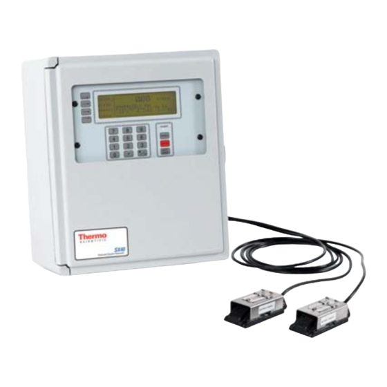
Chapter 1 Product Overview Introduction Thermo Fisher Scientific’s SX40 dedicated Doppler flowmeter generates two independent ultrasonic signals at different frequencies. By correlating these frequencies, the instrument automatically identifies and eliminates noise errors from sources such as variable frequency drives. In addition, operation of the instrument is enhanced by an Expert System that allows the flowmeter to automatically “learn”... -
Page 10: Specifications
Two encapsulated dual frequency sensor heads suitable for submersible/underground service Encased in stainless steel shrouds, with stainless steel straps and quick clamps Cable length: 30 ft. (9 m) Weight: 12 lb. (5.4 kg) Dimensions: Refer to Figure 1–1 SX40 User Guide Thermo Fisher Scientific... -
Page 11: Functional
Display: Backlit, 240 x 60 dot, high resolution graphics display Data Logger: 90000 points, programmable in intervals of 30 s, 1, 5, 15, 30, and 60 min Programming: Via HydraScan software or integral keypad Serial Interface: RS232 Thermo Fisher Scientific SX40 User Guide... -
Page 12: Approvals
Hazardous Area Certification Optional: CSA Class I, Div. 2 or Class II, Div. 2 Optional: CSA Intrinsically Safe Class I, Div. 1; Class II, Div. 1; or Class III, Div. 1 Optional: Intrinsically Safe CENELEC (LCIE) SX40 User Guide Thermo Fisher Scientific... -
Page 13: Chapter 2 Installation & Wiring
E: Sediment collects at the bottom of the horizontal pipe ● Note Selecting the proper installation location is essential to flow measurement reliability. Each application is unique and may require a variation of installation locations. ▲ Thermo Fisher Scientific SX40 User Guide... -
Page 14: Installing The Transducers
Figure 2–2. Recommended transducer orientations 3. Attach the transducers to the pipe strap: a. Use a screwdriver to loosen the mounting screw and slide the lock back on each transducer. Figure 2–3. SX40 User Guide Thermo Fisher Scientific... - Page 15 Remove the strap from the pipe, and apply sonic coupling compound to each transducer surface. f. Reposition the strap on the pipe, placing the transducers in the proper positions. Thermo Fisher Scientific SX40 User Guide...
-
Page 16: Mounting The Enclosure
2. Remove the meter access cover, and locate the 4 mounting holes (1 in each corner of the cover). 3. Attach the enclosure to the wall using the mounting screws. 4. Replace the meter access cover. Note An optional mounting ear package is also available. ▲ SX40 User Guide Thermo Fisher Scientific... -
Page 17: Wiring
If the input voltage is 220 V, second hot wire to L2/N 6. Turn the terminal screws clockwise to close them connections. 7. Ensure the wires are securely connected to the input block, and replace the meter access cover. Thermo Fisher Scientific SX40 User Guide... -
Page 18: Dc Power
3. Make the following connections: a. +24VDC to P2 +24 b. 24 VDC return to either of the P2 GND connections 4. Turn the terminal screws clockwise to close them connections. SX40 User Guide Thermo Fisher Scientific... -
Page 19: Transducers
3. Remove the nut from the transducer cable connector, and draw the cable through the opening in the meter enclosure. 4. Thread the nut onto the cable connector to the inside of the enclosure. Thermo Fisher Scientific SX40 User Guide... - Page 20 Second braided ground wire to RCV GND 10. Turn each screw clockwise to close the connections. 11. Ensure the wire connections are secure, and replace the meter access cover. Figure 2–9. Transducer cable seal assembly SX40 User Guide Thermo Fisher Scientific...
-
Page 21: Relays
3. Locate the 4 relay terminals blocks, and select the relay you are going to wire. 4. Locate the Normally Closed (NC), Common (C), and Normally Open (NO) relay contacts on the terminal block. Thermo Fisher Scientific SX40 User Guide... - Page 22 7. Turn the terminal screws clockwise to close the connections. 8. Ensure the wire connections are secure, and test the relay (see “I/O Test” in Chapter 4). 9. Replace the meter access cover. Figure 2–11. Relay schematic 2-10 SX40 User Guide Thermo Fisher Scientific...
-
Page 23: Ma Current Loop (Rev. F Or Earlier)
VFDs, install wiring in grounded metal conduit. ▲ Note These instructions for instruments with main PCB 22302-0002 Rev. F or earlier. ▲ For instructions on performing a 4–20 mA calibration and/or test, refer to “I/O Test” in Chapter 4. Thermo Fisher Scientific SX40 User Guide 2-11... - Page 24 3. Connect the wiring to the module. 4. Replace the access cover. Figure 2–13. Self-powered current loop & pin configuration Figure 2–14. Externally powered current loop & pin configuration 2-12 SX40 User Guide Thermo Fisher Scientific...
-
Page 25: Ma Current Loop (Rev. G Or Later)
2. Use jumpers to configure the pins on the 4–20 mA card according to the power option selection. 3. Connect the wiring to the module. 4. Replace the access cover. Figure 2–15. Self-powered current loop Thermo Fisher Scientific SX40 User Guide 2-13... -
Page 26: Connecting A Switch To Remote Zero Feature
4. Turn the screws on top of the transducer block counterclockwise to fully open the connections. 5. Make the following connections: a. First switch wire to RLYCOM b. Second switch wire to POSZERO 2-14 SX40 User Guide Thermo Fisher Scientific... - Page 27 Installation & Wiring Wiring 6. Turn the screws clockwise to close the connections. 7. Ensure the wire connections are secure, and replace the meter access cover. Figure 2–17. Remote zero connections Thermo Fisher Scientific SX40 User Guide 2-15...
- Page 28 This page intentionally left blank.
-
Page 29: Chapter 3 Operation & Configuration
2. When the Adjust Contrast screen appears, press the +/- key again, and the software scrolls through the levels of contrast. Press the +/- key to stop the scrolling. 3. Use the scroll and backspace keys to make fine adjustments to the contrast. Thermo Fisher Scientific SX40 User Guide... -
Page 30: Configuration
Warnings” (Table 6–2 in Chapter 6) if you receive one of the following messages: Invalid Signal, Can’t Learn ● No Flow, Can’t Learn ● Warning Low S Strength ● Warning Poor S Strength ● SX40 User Guide Thermo Fisher Scientific... -
Page 31: Manual Mode
Keep damping at a minimum unless the flow rate fluctuates wildly. In this case, increase damping just enough to reduce the fluctuation to an acceptable degree. Press Enter, and scroll to the next parameter. Thermo Fisher Scientific SX40 User Guide... - Page 32 Scroll to the required totalizer unit (US gallons, Imperial gallons, million gallons, cubic feet, cubic meters, liters, oil barrels, liquid barrels) and press Enter. b. Scroll through the available scale factors (x 1, 10, 100, 1000, 10000), and press Enter to select. SX40 User Guide Thermo Fisher Scientific...
- Page 33 12. Select Next, and if a password is required, enter it here. 13. Select Next to move to the final setup screen. 14. Set the time and date at this screen, and press Next to complete the configuration process. Thermo Fisher Scientific SX40 User Guide...
-
Page 34: Hydrascan
Operation & Configuration HydraScan HydraScan You can also use the HydraScan software to configure the instrument. Refer to the HydraScan user guide (P/N 1-0563-005). SX40 User Guide Thermo Fisher Scientific... -
Page 35: Chapter 4 Setup Items
Note You will need a calibrated current meter to perform this procedure. If you are using the loop-powered configuration, you will also need a DC power source. ▲ For wiring instructions, refer to Chapter 2. 1. Set up a calibration current loop. Thermo Fisher Scientific SX40 User Guide... -
Page 36: 4-20 Ma Loop Test
The meter records the maximum flow, date, and time of the maximum flow since the last reset. You can view this information from the Max screen. Reset the data by changing the Max field selection from “Set” to “Clear.” SX40 User Guide Thermo Fisher Scientific... -
Page 37: Chapter 5 Flow Menu Items
Trend runs at a real-time rate of action. To view the flow trend, select Trend from the Flow menu. Rate From the Trend screen, select Rate. Scroll through the available rate options (0.1, 0.5, 1, 5, 15, 60 minutes/reading). Press Enter. Thermo Fisher Scientific SX40 User Guide... -
Page 38: Max
The meter records the maximum flow, date, and time of the maximum flow since the last reset. You can view this information from the Max screen. Reset the data by changing the Max field selection from “Set” to “Clear.” SX40 User Guide Thermo Fisher Scientific... -
Page 39: Chapter 6 Troubleshooting & Maintenance
4. Restart meter. 1. Turn meter off, and remove the transducers. 2. Grind the pipe surface if it is rough or coated. 3. Remount the transducers. 4. Restart the meter. See if warning clears. Thermo Fisher Scientific SX40 User Guide... -
Page 40: Learn Mode Warnings
B–D, checking the meter after performing each action to see if the problem was corrected. Signal Status 2. Check the FFT. 3. Contact Thermo Fisher. IS – Invalid 1. Check the FFT. Signal 2. Contact Thermo Fisher. 6-2 SX40 User Guide Thermo Fisher Scientific... -
Page 41: Variable Frequency Drives (Vfds)
No Doppler Ultrasound signal not 1. Refer to Table 6–1 and complete reflection transmitting action codes A-D, checking the meter after performing each action to see if I or II the problem was corrected. Thermo Fisher Scientific SX40 User Guide 6-3... - Page 42 Troubleshooting & Maintenance General Troubleshooting Figure 6–1. Ideal Doppler shape Figure 6–2. Broadband noise Figure 6–3. Steady noise spike with Doppler Figure 6–4. Fluctuating Doppler profile 6-4 SX40 User Guide Thermo Fisher Scientific...
-
Page 43: Signal Quality & Strength
Refer to the following figure to determine the quality of the application. Also refer to Table 6–1 for actions you can take to attempt to improve signal quality and strength. Figure 6–7. Thermo Fisher Scientific SX40 User Guide 6-5... -
Page 44: Maintenance
2. Remove the meter access cover. 3. Locate the relay sockets (reference Figure 2–11), and remove the relay. 4. Push the replacement relay into the socket until it is secure. 5. Replace the access cover. 6-6 SX40 User Guide Thermo Fisher Scientific... - Page 45 7. Wire and configure the 4–20 mA loop (reference Chapter 8. Reconnect power, and calibrate the current loop according to “4–20 mA Loop Calibration” in Chapter 4. 9. Replace the access cover. Thermo Fisher Scientific SX40 User Guide 6-7...
-
Page 46: Replacing The Fuse
3. Insert a similar fuse of the same rating (see Figure 6–9). 4. Replace the fuse holder. Depress and turn the holder clockwise until it locks in place. 5. Replace the access cover if removed. 6-8 SX40 User Guide Thermo Fisher Scientific... -
Page 47: Upgrades
+1 (713) 4573 fax +44 (0) 1606 548711 fax +86 (10) 8419-3580 fax A-101, 1CC Trade Tower Senapati Bapat Road Pune 411 016 Maharashtra, INDIA +91 (20) 6626 7000 +91 (20) 6626 7001 fax www.thermoscientific.com Thermo Fisher Scientific SX40 User Guide 6-9... -
Page 48: Warranty
5. Send the unit freight-paid to the address above. Warranty Thermo Scientific products are warranted to be free from defects in material and workmanship at the time of shipment and for one year thereafter. Any claimed defects in Thermo Scientific products must be reported within the warranty period. - Page 49 EXCEPT AS OTHERWISE AGREED TO IN WRITING BY Thermo Fisher, THE WARRANTIES GIVEN ABOVE ARE IN LIEU OF ALL OTHER WARRANTIES, EXPRESSED OR IMPLIED, AND Thermo Fisher HEREBY DISCLAIMS ALL OTHER WARRANTIES, INCLUDING THOSE OF MERCHANTABILITY AND FITNESS FOR PURPOSE. Thermo Fisher Scientific SX40 User Guide 6-11...
- Page 50 This page intentionally left blank.
-
Page 51: Appendix A Hazardous Area Installations
Appendix A Hazardous Area Installations Figure A–1. Hazardous area installation with barriers Thermo Fisher Scientific SX40 User Guide... - Page 52 Hazardous Area Installations Figure A–2. Hazardous area installation without barriers SX40 User Guide Thermo Fisher Scientific...
-
Page 53: Appendix B Obtaining Pipe Id
15.688 15.255 14.876 14.438 17.250 17.000 20.000 19.634 19.500 19.250 19.000 18.812 18.376 17.938 17.438 17.000 16.500 16.062 19.250 19.000 24.000 23.564 23.500 23.250 22.876 22.624 22.062 21.562 20.938 20.376 19.876 19.312 23.250 23.000 Thermo Fisher Scientific SX40 User Guide... - Page 54 88.54 84.10 All measurements in inches Note For pipes with cement linings, reduce the pipe ID by twice the lining thickness. Standard and double cement lining thicknesses are listed in the next table. ▲ SX40 User Guide Thermo Fisher Scientific...
- Page 55 49.36 49.22 49.08 48.94 57.10 55.96 55.80 55.64 55.48 55.32 55.16 55.00 All measurements in inches Note For pipes with cement linings, reduce the pipe ID by twice the lining thickness listed above. ▲ Thermo Fisher Scientific SX40 User Guide...
- Page 56 This page intentionally left blank.
-
Page 57: Appendix C Toxic & Hazardous Substances Tables
Appendix C Toxic & Hazardous Substances Tables The English and Chinese versions of the Toxic and Hazardous Substances tables are shown below. Thermo Fisher Scientific SX40 User Guide... - Page 58 This page intentionally left blank.
- Page 59 Thermo Fisher Scientific 81 Wyman Street P.O. Box 9046 Waltham, Massachusetts 02454-9046 United States www.thermofisher.com...
Need help?
Do you have a question about the SX40 and is the answer not in the manual?
Questions and answers