Table of Contents
Advertisement
Advertisement
Table of Contents

Related Manuals for Siemens SIMATIC MICRO-DRIVE PDC1000


Summary of Contents for Siemens SIMATIC MICRO-DRIVE PDC1000
- Page 1 PDC1000(F)
- Page 2 Preface Documentation guide SIMATIC Product overview Connecting MICRO-DRIVE PDC1000(F) Alarms, diagnostics, error messages and system events Equipment Manual Technical specifications Response times Dimension drawing Translated from original Equipment Manual 02/2020 A5E48775040-AA...
- Page 3 Note the following: WARNING Siemens products may only be used for the applications described in the catalog and in the relevant technical documentation. If products and components from other manufacturers are used, these must be recommended or approved by Siemens. Proper transport, storage, installation, assembly, commissioning, operation and maintenance are required to ensure that the products operate safely and without any problems.
-
Page 4: Preface
Purpose of the documentation This manual supplements the system manual SIMATIC MICRO-DRIVE Drive controller PDC (https://support.industry.siemens.com/cs/ww/en/view/109774126). The manual contains a compact description of the device-specific information. The system-related functions are described in the system manual. All system-spanning functions are described in the function manuals. - Page 5 Siemens' products and solutions undergo continuous development to make them more secure. Siemens strongly recommends that product updates are applied as soon as they are available and that the latest product versions are used. Use of product versions that are no longer supported, and failure to apply the latest updates may increase customers' exposure to cyber threats.
- Page 6 Preface Industry Mall The Industry Mall is the catalog and order system of Siemens AG for automation and drive solutions on the basis of Totally Integrated Automation (TIA) and Totally Integrated Power (TIP). You can find catalogs for all automation and drive products on the Internet (https://mall.industry.siemens.com) and in the Information and Download Center.
-
Page 7: Table Of Contents
Table of contents Preface ..............................3 Documentation guide ..........................7 Product overview ............................. 11 Area of application of the PDC drive controller ..............11 Properties ..........................12 Power supply .......................... 15 Calculating the overload capability of the power unit............. 17 Connecting .............................. -
Page 8: Documentation Guide
The function manuals contain detailed descriptions on general topics regarding the MICRO- DRIVE servo drive system and SIMATIC S7-1500 automation system, such as diagnostics, communication, Motion Control, Web server and OPC UA. You can download the documentation free of charge from the Internet (https://support.industry.siemens.com/cs/ww/en/ps/25460). PDC1000(F) Equipment Manual, 02/2020, A5E48775040-AA... - Page 9 S7-1200 product family. In addition to the system manual, the S7-1200 Easy Book provides a general overview of the capabilities of the S7-1200 family. You can download or view the electronic manuals on the Siemens Industry Online Support (https://support.industry.siemens.com) website.
- Page 10 ● Manuals, characteristics, operating manuals, certificates ● Product master data You can find "mySupport" - CAx data on the Internet (https://support.industry.siemens.com/my/ww/en/CAxOnline). Application examples The application examples support you with various tools and examples for solving your automation tasks. Solutions are shown in interplay with multiple components in the system - separated from the focus on individual products.
- Page 11 You can find the SIMATIC Automation Tool on the Internet (https://support.industry.siemens.com/cs/ww/en/view/98161300). PRONETA SIEMENS PRONETA (PROFINET network analysis) allows you to analyze the plant network during commissioning. PRONETA features two core functions: ● The topology overview automatically scans the PROFINET and all connected components.
-
Page 12: Product Overview
Product overview Area of application of the PDC drive controller Areas of application You can use the SIMATIC MICRO-DRIVE drive system in different industry sectors that require powerful positioning drives. SIMATIC MICRO-DRIVE has proven to be an ideal drive in numerous applications. The system excels in dynamic positioning tasks in production and manufacturing and in innovative application areas. -
Page 13: Properties
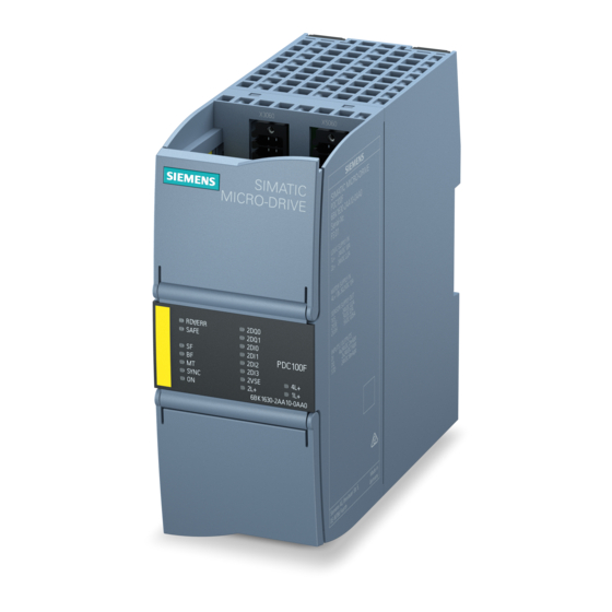
Product overview 2.2 Properties Properties Article number PDC1000 drive controller 6BK1630-1BA00-0AA0 6BK1630-1AA00-0AA0 PDC1000F drive controller 6BK1630-2AA00-0AA0 View of the device The figure below shows the PDC1000 drive controller. Figure 2-1 Product image PDC1000 The fail-safe variant PDC1000F has yellow enclosure markings as well as yellow connectors. PDC1000(F) Equipment Manual, 02/2020, A5E48775040-AA... - Page 14 Product overview 2.2 Properties Properties The PDC1000 has the following technical properties: Property Description Additional information Control of EC motors The PDC1000 is a motor controller for Section Connecting the motor three-phase motors (EC) with supply (Page 26). voltages to 48 V DC and permanent magnets.
- Page 15 The PDC1000 has no internal braking System Manual SIMATIC MICRO- resistor. To absorb the regenerative DRIVE Drive controller PDC energy of the motor, you must connect (https://support.industry.siemens.com/c an external braking resistor. s/ww/en/view/109774126) Hardware STO Safety function "Hardware STO" (Safe System Manual SIMATIC MICRO-...
-
Page 16: Power Supply
It is essential that you observe the information on recovery in the section "Energy recovery" in the System Manual SIMATIC MICRO-DRIVE Drive controller PDC (https://support.industry.siemens.com/cs/ww/en/view/109774126). WARNING Use separate power supply units to supply the logic unit and the power unit or a filter between the shared power supply unit and the power supply. - Page 17 "Accessories/Spare parts" in the System Manual SIMATIC MICRO-DRIVE Drive controller PDC (https://support.industry.siemens.com/cs/ww/en/view/109774126). The miniature circuit breaker must be implemented with two poles even when using PELV. In order for the DC link capacitors to be charged slowly when 4L+ is switched on, we recommend a primary-switched electronic power supply with current limitation.
-
Page 18: Calculating The Overload Capability Of The Power Unit
60 V DC with inactive control. Reference Note the detailed information on the power supply in the System Manual SIMATIC MICRO- DRIVE Drive controller PDC (https://support.industry.siemens.com/cs/ww/en/view/109774126). See also Terminal assignment (Page 18) Calculating the overload capability of the power unit The following table shows the relationship between overload and recovery of the power unit. -
Page 19: Connecting
Connecting Terminal assignment Connection options on the PDC1000 The figure below shows the connection possibility on the PDC1000 drive controller. ① Power supply of power unit (X5050) ② Logic supply of PDC (X5060) ③ Hardware STO (X5060) ④ SSI absolute encoder (X5060) ⑤... - Page 20 SIMATIC MICRO-DRIVE Drive controller PDC. The SIMATIC MICRO-DRIVE drive system is compatible with motors (Dunkermotoren, ebm- papst) and connecting cables (Harting, KnorrTec) of proven product partners of Siemens. This allows you to optimally combine suitable products from proven product partners for your individual application.
- Page 21 Connecting 3.1 Terminal assignment Interfaces, cable lengths and cable types The following cable lengths and cable types are permitted for the interfaces. Table 3- 1 Wiring rules for the interfaces Plug connector Function Maximum cable length Cable type Cable cross-section X100 Functional ground 0.1 m...
- Page 22 Connecting 3.1 Terminal assignment Plug connector Function Maximum cable length Cable type Cable cross-section X5060 Logic supply PDC (1L+, 20 m Solid and stranded sup- < 2 m unshielded • ply cable: ≥ 2 m shielded • AWG*: 20 to 16 or 0.5 mm to 1.5 mm For through-wiring for...
-
Page 23: Schematic Circuit Diagram
Connecting 3.2 Schematic circuit diagram Schematic circuit diagram The following figure shows the schematic circuit diagram of the PDC1000 drive controller. ① X4060: Connection for digital outputs X4060 Infeed of supply voltage for digital in- 24 V DC puts/outputs ② X4060: Connection for digital inputs X5060 24 V DC Infeed of supply voltage for logic unit ③... -
Page 24: Connecting The Supply Voltages
● Only wire the connection plug when the supply voltage is turned off. ● Observe the rules and regulations on operation described in the System Manual SIMATIC MICRO-DRIVE Drive controller PDC (https://support.industry.siemens.com/cs/ww/en/view/109774126). ● Observe the rules and regulations described in section Product overview (Page 11). Required tool Screwdriver (recommended): ●... - Page 25 Connecting 3.3 Connecting the supply voltages Connection of supply voltages for the PDC logic unit and the inputs/outputs (24 V DC) ● Pin assignment: Interface X4060 for supply voltage of inputs/outputs Table 3- 2 Pin assignment: Interface X4060 for supply voltage of inputs/outputs Designation Function Designation...
- Page 26 Press the spring release as far as it will go with the screwdriver. Remove the wire. Reference Note the detailed information on the topic "Connecting" in the System Manual SIMATIC MICRO-DRIVE Drive controller PDC (https://support.industry.siemens.com/cs/ww/en/view/109774126). PDC1000(F) Equipment Manual, 02/2020, A5E48775040-AA...
-
Page 27: Connecting The Motor
Reference The SIMATIC MICRO-DRIVE drive system is compatible with motors (Dunkermotoren, ebm- papst) and connecting cables (Harting, KnorrTec) of proven product partners of Siemens. This allows you to optimally combine suitable products from proven product partners for your individual application. You can find more information about the Siemens Product Partner Program on the Internet (https://new.siemens.com/global/en/company/topic-... -
Page 28: Connecting An External Braking Resistor
3.5 Connecting an external braking resistor Reference Note the detailed information on the topic "Connecting" in the System Manual SIMATIC MICRO-DRIVE Drive controller PDC (https://support.industry.siemens.com/cs/ww/en/view/109774126). Connecting an external braking resistor Connecting an external braking resistor WARNING Damage to braking resistor - Risk of fire! You must implement fire prevention measures for the external braking resistor (e.g. - Page 29 Note the detailed information on connection of an external braking resistor in the System Manual SIMATIC MICRO-DRIVE Drive controller PDC (https://support.industry.siemens.com/cs/ww/en/view/109774126). You can also find information on the topic of "Accessories/spare parts" in the System Manual SIMATIC MICRO-DRIVE Drive controller PDC.
-
Page 30: Alarms, Diagnostics, Error Messages And System Events
Alarms, diagnostics, error messages and system events Status and error display The PDC has LED displays for indicating the current operating state and the diagnostics status. The drive is ready for operation when the "RDY/ERR" is off. A steady green "RDY/ERR" LED indicates that the drive is in operation. - Page 31 Alarms, diagnostics, error messages and system events 4.1 Status and error display The LEDs assume different statuses during startup. The displays of the LEDs operate independent of one except during firmware update. The figure below shows the various LED displays on the PDC. ①...
- Page 32 LEDs for the status of the drive controller in the System Manual SIMATIC MICRO-DRIVE Drive controller PDC (https://support.industry.siemens.com/cs/ww/en/view/109774126) You can find additional information on the topic of "Interrupts" in the STEP 7 online help.
-
Page 33: Technical Specifications
Technical specifications of the PDC1000 (article number 6BK1630-1BA00-0AA0) The following table shows the technical specifications of the PDC1000 as of 02/2020. You can find a data sheet including daily updated technical specifications on the Internet (https://support.industry.siemens.com/cs/ww/en/ps/25460). Article number 6BK1630-1BA00-0AA0 General information... - Page 34 Technical specifications 5.1 Technical Specifications PDC1000 Article number 6BK1630-1BA00-0AA0 Supply voltage of the motor 24 ... 48 V DC, SELV / PELV Type of motor voltage • 19.2 V permissible range, lower limit (DC) • 57.6 V permissible range, upper limit (DC) •...
- Page 35 Maximum 1 000 J per braking process, maximum 1 000 J per minute You can find information on the general technical specifications, such as standards and approvals, electromagnetic compatibility, protection class, etc., in the System Manual SIMATIC MICRO-DRIVE Drive controller PDC (https://support.industry.siemens.com/cs/ww/en/view/109774126). PDC1000(F) Equipment Manual, 02/2020, A5E48775040-AA...
-
Page 36: Derating Of The Drive Controller Pdc1000
Technical specifications 5.2 Derating of the drive controller PDC1000 Derating of the drive controller PDC1000 Maximum permitted output current as a function of installation altitude and ambient temperature You must take into account the dependency on the ambient temperature and installation altitude. - Page 37 Technical specifications 5.2 Derating of the drive controller PDC1000 The figure below shows the maximum permitted output current as a function of the ambient air temperature for the derating. Figure 5-2 Derating for PDC as a function of the ambient temperature Coincidence factors of inputs/outputs Also note the permissible coincidence factors of the inputs/outputs.
-
Page 38: Response Times
The response time is the time between the detection of an input signal and the change of a linked output signal. You will find the response times of the SIMATIC MICRO-DRIVE drive system on the Internet (https://support.industry.siemens.com/cs/ww/en/ps/25460). The response times of the drive enter into the calculation of the response time of the F-system. -
Page 39: Dimension Drawing
Dimension drawing This appendix contains the dimension drawings of the MICRO-DRIVE PDC1000 installed on a mounting rail. You must take into account the dimensions for installation in cabinets, control rooms, etc. Dimension drawings of the MICRO-DRIVE PDC1000 Figure B-1 Dimension drawings of MICRO-DRIVE PDC1000, front and side view (as examples, depending on mounting rail type used) PDC1000(F) Equipment Manual, 02/2020, A5E48775040-AA...
Need help?
Do you have a question about the SIMATIC MICRO-DRIVE PDC1000 and is the answer not in the manual?
Questions and answers