Table of Contents
Advertisement
Quick Links
830-629-2900 / 800-729-3839 / Fax 800-653-3839 / Text photos only: 830-481-6433 / INTERNET: www.detex.com
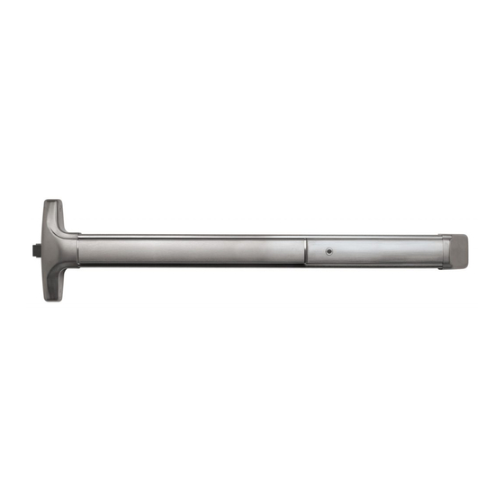
Concealed Vertical Rod Exit Device
87 Series - High security
for Medium to Wide Stile
Hollow Metal door applications
Drawing No: 106700
Table of Contents
Device parts breakdown view......................................................................
Device parts breakdown list with part numbers...........................................
Hardware List with part numbers & tool required........................................
Door condition check...................................................................................
Step 1: Door/opening measurements..........................................................
Step 2: Door prep - hollow metal door.........................................................
Step 3: Top rod assembly & initial adjustment (80" to 96" door).................
Step 4: Bottom rod/latch assembly & adjustment.......................................
Step 5: Visual alignment check...................................................................
Step 6: Attach top latch mounting brackets.................................................
Step 7: Insert rod/latch/centerlift assembly into door...................................
Step 8: Secure rod/latch/centerlift assembly to door....................................
Step 9: Verify centerlift mechanism operation.............................................
Step 10: Hang door/assemble device to door..............................................
Step 11: Top strike installation.....................................................................
Step 12: Bottom strike installation................................................................
Step 13: Fine latch adjustment.....................................................................
Step 14: Cover installations..........................................................................
Optional accessories.....................................................................................
For WARRANTY information,
scan code below or
go to www.detex.com/warranty
Detex Corporation, 302 Detex Drive, New Braunfels, Texas 78130-3045
R
Check device clearance.................................................................
Install endcap bracket....................................................................
Mortise cylinder installation...........................................................
Owner's Copy
Should you have a Question/Problem with your Detex device please
call Detex Technical Support from the job site at 1-800-729-3839
and choose option 2 on our menu. Please do not return the product
to the distributor.
104924 Page 1
104924
March 18, 2020
Page
For device installation
videos, scan code below
or go to www.detex.com/videos
B
2
3
4
6
6
7
8
9
10
11
12
12
13
14
15
15
16
16
17
18
18
19
20
Advertisement
Table of Contents

Related Manuals for Detex ADVANTEX 87 Series


Summary of Contents for Detex ADVANTEX 87 Series
-
Page 1: Table Of Contents
104924 March 18, 2020 Detex Corporation, 302 Detex Drive, New Braunfels, Texas 78130-3045 830-629-2900 / 800-729-3839 / Fax 800-653-3839 / Text photos only: 830-481-6433 / INTERNET: www.detex.com Concealed Vertical Rod Exit Device 87 Series - High security for Medium to Wide Stile... -
Page 2: Device Parts Breakdown View
Parts listed will vary according to product configuration. Mortise cylinder available as an option. Standard Yale type cam required. See Mortise cylinder installation page. Your particular part or configuration may not be shown: Contact Detex technical support at 800-729-3839 (option 2) 20 KIT 1KIT 104924 Page 2... -
Page 3: Device Parts Breakdown List With Part Numbers
Your particular part or configuration may not be shown: Contact Detex technical support at 800-729-3839 (option 2) PARTS BREAKDOWN Item Description Part # 105500-165 S&R Centercase/Pushpad Assy, ADV 87 x STD1 x RHR, 36", 630 1KIT (Includes Item 1A) 105500-166 S&R Centercase/Pushpad Assy, ADV 87 x STD1 x LHR, 36", 630... -
Page 4: Hardware List With Part Numbers & Tool Required
Hardware Table for BASIC device mounting. Additional hardware is provided per the device configuration in kit form and is addressed on the appropriate pages as required. Fastener Table ADVANTEX 87 Device Mounting Hardware Screw style & size Used on and Drill Bit used Description 1/4-20 x 1"... - Page 5 Fastener Table ADVANTEX 87 Strike Mounting Hardware Used to install bottom strike to floor #10 x 1" self-cutting PFH (used with anchors, two styles of anchor included) P/N: 100109 10-24 x 1/2" PFH Used to install bottom strike to floor (alternate) P/N: 100112-108 10-32 x 5/8"...
-
Page 6: Door Condition Check
Unreinforced Doors: Use Sex Nuts and Bolts Minimum Stile Width: 4-1/2" Unreinforced Frames: Use Blind Rivet Nuts (see sketch). Fasteners for unreinforced openings are not supplied by Detex. Reinforced door or Reinforcement frame engages at least (3) screw threads. -
Page 7: Step 2: Door Prep - Hollow Metal Door
DOOR FRAME HEADER stop and header Door open direction TOP STRIKE TEMPLATE Template #105299-1 ALIGN template with latch and device vertical DEVICE centerline VERTICAL *NOTE: FOR FURTHER DOOR CONSTRUCTION & FRAME PREP DETAILS, SEE TEMPLATE T2341 ON DETEX WEBSITE 104924 Page 7... -
Page 8: Step 3: Top Rod Assembly & Initial Adjustment (80" To 96" Door)
STEP 3: TOP ROD ASSEMBLY & INITIAL ADJUSTMENT For 6'-8" (80") to 8'-0" (96") Door 3a. Align hole A in rod 104187 with hole in top latch as shown at right & tap the 13/16" long pin into latch hole. 3b. -
Page 9: Step 3: Top Rod Assembly & Initial Adjustment (97" To 120" Door)
STEP 3: TOP ROD ASSEMBLY & INITIAL ADJUSTMENT For 8'-1" (97") to 10' (120") Door 3a. Align hole A in rod 105097 with hole in top latch as shown at right & tap the 13/16" long pin into latch hole. 3b. -
Page 10: Step 4: Bottom Rod/Latch Assembly & Adjustment
STEP 4: BOTTOM ROD / LATCH ASSEMBLY & ADJUSTMENT Align rod holes with bottom latch (round DIM A to nearest value shown) 4a. Using DIM A as measured in step 1, DIM A Bottom Rod use chart to determine pinning location. (device C at p/n: 105098 distance from floor ) -
Page 11: Step 5: Visual Alignment Check
STEP 5: VISUAL ALIGNMENT CHECK: 3/8" from top of door to latch body 5a. Lay internal latch components onto door for trial fit. Take care to protect door finish. Latch must be in 5b. Ensure top latch is in retracted RETRACTED position position. -
Page 12: Step 6: Attach Top Latch Mounting Brackets
STEP 6: ATTACH TOP LATCH MOUNTING BRACKETS ATTACH top latch mounting brackets as shown below. Three screws required for each bracket. Top latch mounting bracket Top latch mounting bracket P/N 106150-1 P/N 106150-2 ATTACH top latch mounting bracket to top latch assembly with (3) button head socket cap screws ATTACH top latch mounting 10-24 x 1/4"... -
Page 13: Step 8: Secure Rod/Latch/Centerlift Assembly To Door
STEP 8: SECURE ROD / LATCH / CENTERLIFT ASSEMBLY TO DOOR 8a. Attach top latch to door with six screws. 8b. Attach bottom bolt mounting brackets to bottom bolt case ATTACH top latch to door with six screws. with (6) phillips pan head screws 8c. -
Page 14: Step 9: Verify Centerlift Mechanism Operation
STEP 9: VERIFY CENTERLIFT MECHANISM OPERATION With latch bolt extended, top adjustment screw should be exposed. HOLDBACK If not, go back to STEP 3 and make BRACKET top rod longer. PUSH CORRECT POSITIONING CORRECT POSITIONING OF ACTIVATION SLOT AND OF ACTIVATION SLOT ADJUSTMENT SCREW AND ADJUSTMENT SCREW IN LATCH RETRACTED... -
Page 15: Step 10: Hang Door/Assemble Device To Door
STEP 10: HANG DOOR / ASSEMBLE DEVICE TO DOOR INSTALL DOOR ONTO FRAME PER MANUFACTURER'S SPECIFICATIONS setscrew LIFT PIN MUST BE ON BOTTOM if required Rehanding procedure liftpin Remove setscrew then liftpin which screws out of the back. MOVE LIFT PIN & SETSCREW TO BOTTOM POSITION ON CARRIAGE. -
Page 16: Install Endcap Bracket
INSTALL ENDCAP BRACKET LEVEL device before installing endcap bracket ENSURE that device does not require cutting (See Step 10f on previous page). TEST device function after installation of endcap is complete by depressing & releasing pushpad. Action should be smooth with full return of pushpad and latch travel. -
Page 17: Step 11: Top Strike Installation
STEP 11: TOP STRIKE INSTALLATION STRIKE ORIENTATION INSTALL LOAD SHIMS Supplemental Screw used Load Shim with shims Load Shims are used to maximize device strength. Utilize to fill-in gap Top strike pocket 8-32 x 1/4" 0 shims between strike insert and strike pocket wall. 1 or 2 shims 8-32 x 5/16"... -
Page 18: Step 12: Bottom Strike Installation
STEP 12: BOTTOM STRIKE INSTALLATION BOTTOM STRIKE HOLE LOCATION & DRILLING DRILL 1/4 hole for plastic anchors P/N: 101129-1 #10 x 1" 95B bottom strike kit P/N: 102642-6 can be ordered as p/n 105257-3 CVR bottom strike P/N: 105249 10-24 x 1/2" With door closed Drill 1"... -
Page 19: Step 14: Cover Installations
DEVICE OPERATION TROUBLESHOOTING SYMPTOM POSSIBLE CAUSE SOLUTION Device not latching Bottom bolt is not properly aligned with bottom strike hole. Modify bottom strike hole for fit. when door closes Top strike insert is not installed or not correctly aligned with Install and/or position strike insert per instructions. -
Page 20: Optional Accessories
Optional Accessories Sex Nut Kits Catalog No: SN3 uses screws in hardware kit The #1/4-20 kits are available in 3 finishes: Brushed Brass BHMA 606: 105274-2 Oil Rubbed Bronze BHMA 613: 105274-25 Stainless Steel BHMA 630: 105274-9 Tamper Kit (Security Kit) Catalog # &...
Need help?
Do you have a question about the ADVANTEX 87 Series and is the answer not in the manual?
Questions and answers