Advertisement
Quick Links
830-629-2900 / 800-729-3839 / Fax 800-653-3839 / Text photos only: 830-481-6433 / INTERNET: www.detex.com
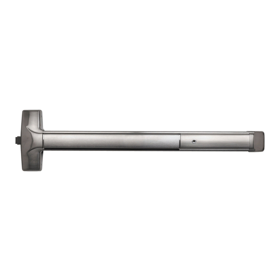
INSTALLATION INSTRUCTIONS FOR CONCEALED VERTICAL ROD
Concealed Vertical Rod Exit Device
60 / F60 / 61 / F61 Series
for Narrow to Wide Stile
Aluminum or FRP door applications
Drawing No. 105260
For WARRANTY information,
scan code below or
go to www.detex.com/warranty
Should you have a Question/Problem with your Detex device please
call Detex Technical Support from the job site at 1-800-729-3839 and
choose option 2 on our menu. Please do not return the product to the
distributor.
Detex Corporation, 302 Detex Drive, New Braunfels, Texas 78130-3045
R
Table of Contents
Device parts breakdown view................................................
Device parts breakdown list with part numbers.....................
Hardware List with part numbers & tools required.................
Step 1: Door/opening measurements....................................
Step 2: Door & frame prep ...................................................
Step 3: Top rod assembly and initial adjustment .................
Step 4: Bottom rod / latch assembly initial adjustment .........
Step 5: Visual alignment check ............................................
Step 6: Install top latch mounting bracket ............................
Step 7: Insert rod / latch / centerlift assembly into door .......
Step 8: Secure rod / latch / centerlift assembly to door .......
Step 9: Verify centerlift mechanism operation ...................
Step 10: Hang door / assemble device to door ....................
Check device for clearance ....................................
Install mortise cylinder ...........................................
Step 11: Install top strike.......................................................
Step 12: Install bottom strike.................................................
Step 13: Fine latch adjustment .............................................
Step 14: Install covers ..........................................................
Step 15: Install auxiliary bolt.................................................... 17
Optional accessories ............................................................
Owner's Copy
104884 Page 1
104884
March 18, 2020
Page
2
3
4
5
6
7 & 8
9
10
11
11
12
12
13
14
14
15
15
16
17
18
For device installation videos,
scan code below or
go to www.detex.com/videos
B
Advertisement

Subscribe to Our Youtube Channel
Related Manuals for Detex ADVANTEX 60 Series


Summary of Contents for Detex ADVANTEX 60 Series
- Page 1 104884 March 18, 2020 Detex Corporation, 302 Detex Drive, New Braunfels, Texas 78130-3045 830-629-2900 / 800-729-3839 / Fax 800-653-3839 / Text photos only: 830-481-6433 / INTERNET: www.detex.com INSTALLATION INSTRUCTIONS FOR CONCEALED VERTICAL ROD Concealed Vertical Rod Exit Device 60 / F60 / 61 / F61 Series...
- Page 2 Parts listed will vary according to product configuration. Mortise cylinder available as an option. Standard Yale type cam required. See Mortise cylinder installation page. Your particular part or configuration may not be shown: Contact Detex technical support at 800-729-3839 (option 2) 14 KIT 1KIT 104884 Page 2...
- Page 3 Fillerplate Subassembly, S&R, Hex Dogging, LD, 630 104112-9 Centercase Cover, Stainless Steel, Narrow 630/628 Hex Dogging Assembly 102216-2 Cylinder Dogging Assembly 102216 Your particular part or configuration may not be shown: Contact Detex technical support at 800-729-3839 (option 2) 104884 Page 3...
- Page 4 Hardware Table for BASIC device mounting. Additional hardware is provided per the device configuration in kit form and is addressed on the appropriate pages as required. Device Mounting Hardware Used to install backplate & endcap bracket to hollow #14 x 1" PPHS metal/aluminum doors.
- Page 5 Unreinforced Doors: Use Sex Nuts and Bolts Minimum Stile Width: 2" Unreinforced Frames: Use Blind Rivet Nuts (see sketch). Fasteners for unreinforced openings are not supplied by Detex. Reinforced door or Reinforcement frame engages at least (3) screw threads.
- Page 6 DOOR OPEN DIRECTION Top strike template Template #105299 ALIGN TEMPLATE WITH LATCH AND DEVICE VERTICAL CENTERLINE *NOTE DEVICE VERTICAL FOR FURTHER DOOR CONSTRUCTION & FRAME PREP DETAILS, SEE TEMPLATE T2300 OR T2301 (FOR TRO) ON DETEX WEBSITE (WWW.DETEX.COM) 104884 Page 6...
- Page 7 For 6'-8" (80") to 8'-0" (96") Door STEP 3: TOP ROD ASSEMBLY & INITIAL ADJUSTMENT 3a. Align hole A in rod 104187 with hole in top latch as shown at right & tap the 13/16" long pin into latch hole. 3b.
- Page 8 For 8'-1" (97") to 10' (120") Door STEP 3: TOP ROD ASSEMBLY & INITIAL ADJUSTMENT 3a. Align hole A in rod 105097 with hole in top latch as shown at right & tap the 13/16" long pin into latch hole. 3b.
- Page 9 STEP 4: BOTTOM ROD / LATCH ASSEMBLY & ADJUSTMENT (Disregard if TRO device is being installed) Align rod holes with bottom latch (round DIM A to nearest value shown) 4a. Using DIM A as measured in step 1, DIM A Bottom Rod use chart to determine pinning location.
- Page 10 STEP 5: VISUAL ALIGNMENT CHECK: Top latch case 5a. Lay internal latch components onto door for trial fit. Take care to protect door finish. Latch must be in RETRACTED position 5b. Ensure top latch is in retracted position. for holes to align. Hold top rod in place and push top latch case towards device until latchbolt is...
- Page 11 STEP 6: ATTACH TOP LATCH MOUNTING BRACKETS No brackets necessary for aluminum door applications - continue to step 7 STEP 7: INSERT ROD / LATCH / CENTERLIFT ASSEMBLY INTO DOOR 7a. Align surfaces as shown below. 7b. Gently insert assembly through door top, taking care to maintain assembly orientation. 104884 Page 11...
- Page 12 104884 Page 12...
- Page 13 STEP 10: HANG DOOR / ASSEMBLE DEVICE TO DOOR INSTALL DOOR ONTO FRAME PER MANUFACTURER'S SPECIFICATIONS setscrew if required Rehanding procedure LIFT PIN MUST BE ON BOTTOM liftpin Remove setscrew then liftpin which screws out of the back. MOVE LIFT PIN & SETSCREW TO BOTTOM POSITION ON CARRIAGE.
- Page 14 CHECKING FOR DEVICE CLEARANCE (Cut-Off procedure if required) Slide endcap assembly onto extrusion Cut fillerplate and extrusion STRAIGHT & SQUARE to desired length and deburr Minimum Secure with tape Fillerplate before cutting Length Type Length (L) 2-1/2" CAUTION: HD/CD 3" Check for device and door frame clearance.
- Page 15 STEP 11: TOP STRIKE INSTALLATION Door frame header Door stop Begin strike installation with Tilt strike pocket Top strike pocket notched side of pocket towards to fit into cutout inside door face. If additional adjustment is needed, rotate Top strike pocket Shim Strike insert Door stop side...
- Page 16 STEP 13: FINE LATCH ADJUSTMENT 13a. Ensure that latches are fully retracted. Gently close door. Latches should extend when door is closed. 13b. Depress pushpad and open door. Top latch should clear top strike & bottom bolt should not drag. Latches should remain in retracted position with pushpad released.
- Page 17 The popper is designed to project a spring loaded bolt into the adjacent frame or door in the event of fire. Detex recommends installing the popper in the edge of the door 12" above the threshold or finished floor. Holes for the popper and plug must be aligned with each other.
- Page 18 Optional Accessories Sex Nut Kits Catalog No: SN3 (uses screws in hardware kit) The #1/4-20 kits are available in 3 finishes: Brushed Brass BHMA 606 p/n 105274-2 Oil Rubbed Bronze BHMA 613 p/n 105274-25 Stainless Steel BHMA 630 p/n 105274-9 Tamper Kit (Security Kit) Catalog # &...
Need help?
Do you have a question about the ADVANTEX 60 Series and is the answer not in the manual?
Questions and answers