BE QUIET! DARK BASE PRO 900 User Manual
Hide thumbs
Also See for DARK BASE PRO 900:
- User manual ,
- User manual (11 pages) ,
- User manual (78 pages)
Advertisement
Quick Links
Advertisement

Related Manuals for BE QUIET! DARK BASE PRO 900


Summary of Contents for BE QUIET! DARK BASE PRO 900
- Page 1 rev. 2 USER MANUAL...
-
Page 2: Warranty
INTRODUCTION We are delighted you have chosen to buy our Dark Base PC case. Please read the information here and carefully follow all the instructions prior to installation. Should you have further questions, please contact our customer service. See contact information in the manufacturer’s details section. Warranty ∙... -
Page 3: Specifications
SPECIFICATIONS Dimensions (W x H x D in 243 x 586 x 577 Case type Full tower Material 0.8mm – 1mm SECC, 0.8mm aluminum, ABS plastic, 4mm tinted and tempered glass Motherboard compatibility E-ATX, XL-ATX, ATX, M-ATX, Mini-ITX Front I/O connectors 2x USB 3.0, 1x USB 3.1 Type C Gen. - Page 4 CONTENTS Images Part Name Amount Usage LCS bracket Attaching liquid cooling pumps, etc. Fan bracket Mounting a third fan on the front HDD screw Affixing the HDD M3 screw Fastening the SSD Affixing the motherboard and SSD 6#32 screw bracket Stand-off screw Securing an E-ATX motherboard Knurled-head M3 Affixing an ODD Cable ties Cable management...
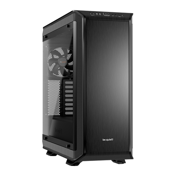
- Page 5 EXPLODED VIEW AND DESCRIPTION OF PARTS Side window of tempered glass Front I/O panel Fastening screws Case body ODD cage Floor air filter HDD cage Case floor PSU mounting Silent Wings 3 fan Double HDD slot cover SSD bracket HDD slot covers PCB panel Rear slot covers Motherboard tray Rear PSU shroud...
- Page 6 4.1 Front I/O and media ports USB 3.0 USB 3.1 Type C Gen. 2 HD audio (microphone and audio) Quick charging option Power button Stepless fan controller LED control switch Qi charging station HDD LED 4.2 I/O ports The front I/O ports that are provided require connections to your motherboard. HD audio (headphone and microphone sockets) Determine the HD audio pin connectors on your motherboard and insert the HD audio cables into the sockets allocated there.
- Page 7 4.3 PCB panel ports PWM connector to the motherboard PWM connector to the fans LED connector to the motherboard LED output for added external LEDs Connector for the supplied LEDs Connector for the Qi charger SATA power connector LED switch connector Connection cable for fan controller slider switch Switches for choosing between Silence and...
-
Page 8: Synchronized Operation
4.5 Installation and handling of the LEDs It is possible to freely position the LED lighting supplied in the case to suit your system setup by affixing and connecting the adhesive strips. The LED strips must be connected to connector “E” on the PCB panel. Description of the LEDs The LED lighting included in the scope of delivery is controllable in several modes of color and operation. Connector “D”...
Need help?
Do you have a question about the DARK BASE PRO 900 and is the answer not in the manual?
Questions and answers