be quiet! Dark Base Pro 900 - PC Cases Manual
- User manual ,
- User manual (72 pages) ,
- User manual (78 pages)
Advertisement
- 1 SPECIFICATIONS
- 2 CONTENTS
- 3 EXPLODED VIEW & PARTS
- 4 LAYOUTS
- 5 FAN COMPATIBILITY
- 6 RADIATOR SUPPORT
- 7 REMOVE EXTERNAL PARTS
- 8 INSTALLATION AND REMOVAL OF DRIVES AND FILTERS
- 9 HDD PANEL REMOVAL/ADJUSTMENT
- 10 M/B TRAY LAYOUT ADJUSTMENT
- 11 PSU LAYOUT ADJUSTMENT
- 12 DOOR PANEL ADJUSTMENT
- 13 COMPONENT INSTALLATION
- 14 Documents / Resources
SPECIFICATIONS

| Dimension (W x H x D in mm) | 242.7 x 585.5 x 577.2 |
| Case Type | Super Midi Tower |
| Material | 0.8mm – 1mm SECC, 0.8mm Aluminum, ABS plastic, Dark Base Pro 900: 4mm tempered glass |
| M/B Support | E-ATX, XL-ATX, ATX, M-ATX, Mini-ITX |
| Front I/O | 2 x USB 3.0, 2 x USB 2.0, HD audio jacks |
| Fan Speed Controller | Dark Base 900: 3x 4-pin, 3 x 3-pin, Controller: manual 5V-12V Dark Base Pro 900: 4x 4-pin, 4x 3-pin, Controller: manual 5V-12V / PWM hub |
| Cooler Height (mm) | 185 |
| Graphics Card Length (mm) | 325 / 470 (w/o HDD trays) |
| PSU Length (mm) | 150 – 284 |
| PCI Slots | 8 |
| 5.25" Bay | 2 |
| 3.5" Bay | 7 |
| 2.5" Bay | 1 + 14 |
| Cooling Fan (mm)/(rpm) | Front: 2x SilentWings ® 3 140 / 1000, Rear: SilentWings ® 3 140 / 1000 |
| Optional Cooling Fan (mm) | Front: 1 x 140 (w/o ODD cage, fan bracket included), Top: 3x 140 / 4 x 120 / 1x 180, Base: 1x 120 / 2x 140 |
| Radiator Support (mm) | 120, 140, 180, 240 (2x 120), 280 (2x 140), 360 (3x 120), 420 (3x 140) |
| Additional Features | Dark Base 900: 2 step side panel bezel Dark Base Pro 900: 2x Multi-Color RGB LED strip, Qi charger |
CONTENTS

EXPLODED VIEW & PARTS
DARK BASE PRO 900

| A | Glass Side Panel Bezel | M | External Base Cover |
| B | Mounting Screws | N | SilentWings ® 3 Fan |
| C | HDD Panel | O | MB-Tray |
| D | HDD Slots | P | SSD-Tray |
| E | PSU Bracket | Q | Fan Speed Controller Board |
| F | Rear Panel Brackets | R | External Front Panel |
| G | Power Adapter Bracket | S | ODD Bezel |
| H | ODD Cage | T | Front Air Filter |
| I | Chassis Body | U | Front Panel Door |
| J | External Top Cover | V | Side Panel |
| K | Front I/O Holder | W | Side Panel Filter |
| L | Base Air Filter | X | Side Panel Bezel |
DARK BASE 900

| A | Side Panel Bezel | M | Base Air Filter |
| B | Side Panel Filter | N | External Base Cover |
| C | Side Panel | O | SilentWings ® 3 fan |
| D | HDD Panel | P | M/B Tray |
| E | HDD slots | Q | SSD Bracket |
| F | PSU Bracket | R | Fan Speed Controller Board |
| G | Rear Panel Brackets | T | External Front Panel |
| H | Power Adapter Bracket | U | ODD Bezel |
| I | ODD Cage | V | Front Air Filter |
| J | Chassis Body | W | Front Panel Door |
| K | External Top Cover | ||
| L | Front I/O Holder |
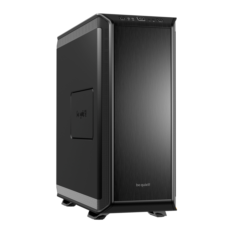
FRONT I/O AND MEDIA PORTS

| A | USB 3.0 | E | USB 2.0 | I | LED Switch (Pro only) |
| B | Headphone | F | Microphone | J | QI Charger (Pro only) |
| C | Power Button / Power LED | G | Reset | ||
| D | HDD LED | H | Fan Speed Controller Switch |
I/O PORTS
The function panel has several wire connections that need to be installed.
HD audio (headphone jack/microphone jack)

Find the "Front panel audio headers/pin connectors" on the motherboard. Plug in the wires according to the motherboard manual.
USB 2.0

Find the "USB 2.0 Headers/pin connectors" on the motherboard. Plug in the wires according to the motherboard manual.
USB 3.0

Find the "USB 3.0 Headers/pin connectors" on the motherboard. Plug in the wires according to the motherboard manual.
Power switch, Power LED, HDD LED, Reset switch

These wires plug into the motherboard where all the front panel switch/pin connectors functions are located. The motherboard manual will have a description of where to plug these in, usually their location is labeled in the motherboard manual.
PCB PANEL / PORTS

DARK BASE PRO 900
- 4-Pin PWM Connector to M/B
- 4-Pin PWM Connector
- 3-Pin Fan Connector
- LED Strip Connector
- Power Connector (SATA)
- Fan Speed Controller Switch Connector
- QI Charger Power Connector
DARK BASE 900
- 4-Pin PWM Connector
- 3-Pin Fan Connector
- Fan Speed Controller Switch Connector
- Power Connector (SATA)
FAN CONTROLLER

The fan controller has two modes of operation.
- Automatic operation
For this the PWM signal of the MB is used and the speed of all fans connected (PWM and 3-pin) can be adjusted automatically through the MB. In this mode the fan controller slider switch must be set to the first position "0" on the far left. - Manual control
When the fan controller slider switch is moved from its first position "0" to the right, the PWM signal is dropped and the fan speed can be regulated manually.
If the slider switch is subsequently reset to its first position "0", the PWM signal regains automatic control of the fans.
Automatic PWM control of the fans requires cable "A" of the PCB panel is connected to a PWM connector on your MB. Lacking such a connection the speed of the fans connected can only be regulated manually.
DARK BASE 900
Dark Base 900 does not have automatic regulation. The speed of all fans (PWM and 3-pin) connected to the PCB panel are manually regulated using the slider switch.
LED INSTALLATION AND USE (ONLY PRO-VERSION)
The LED illumination supplied can be freely positioned and installed in the case according to system configuration using the attached adhesive strips. To power them the lamps must be connected to socket "D" on the PCB panel. Using switch "I" and switches the lamps on and off and permits the illumination color to be selected (red, green, blue, white, orange).
QI Charger use (only Pro-Version)
")
The preinstalled Qi charger supplied with Dark Base Pro 900 allows cable-free charging of all external devices that are compatible with the Qi standard. If the device (e.g. smartphone) is equipped with such a feature it can be charged without cable connection by placing it on the plate marked "J" on the Dark Base Pro 900.
An acoustic signal will indicate that charging has started upon laying the device on the charger.
In so doing please ensure you position the device carefully on the center of the charging plate "J". The charging coil of the Dark Base Pro 900 charging device is located in the middle of charging plate.
LAYOUTS
MB TYPE: ATX (HDD slots facing interior, space for radiator in front of HDD cage)
MB TYPE: E-ATX (HDD slots facing front, space for large motherboard)
Layout A
Case opens to the left

8x PCI Slots / Space for radiator in front of PSU / Space above M/B: 40mm

7x PCI Slots / Space above M/B: 62mm

6x PCI Slots / Space above M/B: 84mm
Layout B
Case opens to the right

8x PCI Slots / Space for radiator in front of PSU / Space above M/B: 55mm

7x PCI Slots / Space above M/B: 77mm

6x PCI Slots / Space above M/B: 99mm
FAN COMPATIBILITY

| Position | Fan Size |
| Top | 4x 120mm, 3 x 140mm, 180mm (mounting points C/C (center to center 154mm) |
| Bottom | 2x 120mm, 2 x 140mm |
| Front | 3x 120mm, 3 x 140mm |
| Rear | 1x 120mm, 140mm |
| Side | 2x 120mm (Dark Base 900) |
RADIATOR SUPPORT

| Position | Radiator Size (mm) |
| Top | 120, 140, 180*, 240, 280, 360, 420 |
| Bottom | 120, 140, 280 |
| Front | 120, 140, 240, 280, 360, 420 |
| Rear | 120, 140 |
*Mounting point of 180mm radiator is c/c 154mm
REMOVE EXTERNAL PARTS
SIDE PANEL REMOVAL
Remove the thumb screw nuts to remove glass panel
Loosen the thumb screws to remove the steel side panel

LED light can be installed in top, bottom and front areas

Side vent can be opened in two different amounts

TOP COVER REMOVAL

Frist remove the front panel. Locate the 8 hooks under the top cover and push them outwards to free the top cover
Lift the top cover to remove
FRONT PANEL REMOVAL
Open the front panel door and first remove the base air filter

Release the hooks to free the front panel

Pull the front panel to release

BASE COVER & CASE STAND REMOVAL
Remove the two screws on the base cover

Push the chassis forward and lift up the chassis to release it from the lower cover

To detach the stand, release the hooks, and push out the stand from the lower cover

INSTALLATION AND REMOVAL OF DRIVES AND FILTERS
5.25" DEVICE (ODD) INSTALLATION
Remove the 5.25" bezel, and slide a 5.25" device into the cage
 INSTALLATION - Step 1")
Secure the 5.25" device with thumb screws
 INSTALLATION - Step 2")
ODD CAGE REMOVAL
Remove the front I/O module and screws to release the ODD cage

Install the Upper Fan Bracket for an additional front intake fan

3.5" DEVICE (HDD) INSTALLATION
Install HDDs with 4 screws inside the 3.5" slot
 INSTALLATION - Step 1")
SSD can also be installed inside the 3.5" slot
 INSTALLATION - Step 2")
HDD RUBBER GROMMETS
Rubber grommets can be fitted to use the HDD bay as a cable management opening

2.5" DEVICE (SSD) INSTALLATION
Release the SSD bracket on the rear of M/B tray
 INSTALLATION")
Install the SSD onto the SSD bracket

AIR FILTER REMOVAL
Pull out the base air filter and front filters to remove

Release the air filter from the side panel

HDD PANEL REMOVAL/ADJUSTMENT
Remove the 5.25" HDD slots

Remove the lower two 3.5" HDD slots

Release the HDD panel by undoing the screws

Rotate the HDD panel 180 degrees

Secure the HDD panel with screws

To setup an inverted M/B layout
Install the HDD panel on the opposite side of the case

Remove the rubber grommets from the rear panel brackets and re-install them on the opposite side of the bracket

M/B TRAY LAYOUT ADJUSTMENT
Mounting points on the rear side of the M/B tray

Mounting points on the front side of the M/B tray

Mounting points on chassis, three steps of adjustment up and down

Remove the screws to release the M/B tray

The M/B tray can act as a test bench

Adjust the M/B position and re-secure the M/B tray

ADJUSTMENT OF REAR PANEL BRACKETS
Remove the rear panel bracket by removing the screws from the side

Reposition the rear panel bracket to close up the gap, and fix with screws

To swap the M/B to other side of the case both the HDD panel and power supply bracket need to be relocated. We recommend removal of the M/B tray, HDD panel, ODD cage, and PSU brackets if you want to change the layout

PSU LAYOUT ADJUSTMENT
Remove the power adapter bracket and rear panel brackets

Remove the PSU bracket and swap the step screws on the base as in diagrams P1 to P4

Re-install all the brackets and screws

Mounting points for Power Adapter Bracket and Rear Panel Brackets

P1 for M/B layout A3, A4, A5, A6
Step screw mounting points

P2 for M/B layout A3, A4, A5, A6
Step screw mounting points

P3 for M/B layout A1, A2, B1, B2
Step screw mounting points

P4 for M/B layout A1, A2, B1, B2
Step screw mounting points

P5 for M/B layout B3, B4, B5, B6
Step screw mounting points

P6 for M/B layout B3, B4, B5, B6
Step screw mounting points

DOOR PANEL ADJUSTMENT
Remove the door panel from the front panel

Remove all the hinges and magnet holders

Depress the push-and-release-kits to release them from the front panel door

Fit the push-and-release-kits to other side of the door

Re-install the hinges and magnet holders to the opposite side of the door panel

Re-install the door panel in the front panel

COMPONENT INSTALLATION
MOTHERBOARD INSTALLATION
Secure the M/B with M3 screws. Stand-offs are pre-installed for an ATX M/B

POWER SUPPLY (PSU) INSTALLATION
Remove the screws to detach the PSU mounting bracket
 INSTALLATION - Step 1")
Secure the PSU with the screws
 INSTALLATION - Step 2")
Before sliding the PSU bracket into position, please connect the power adapter cable to the PSU and secure the PSU bracket to the chassis with screws
 INSTALLATION - Step 3")
PCI/PCI-E ADD-ON CARD INSTALLATION
Remove the PCI slot bracket before installing a PCI / PCI-E add-on card

WATER COOLING OPTION
Water cooling system (WCS) bracket
Fit the pump to the WCS bracket with rubber grommets (screws and nuts are not included)

Fit the WCS bracket and pump on the HDD slot and secure it with a screw

WCS CYLINDER WATER TANK INSTALLATION
Install the holder support on the HDD panel

Manufacturer's details
Listan GmbH & Co. KG | Biedenkamp 3a | 21509 Glinde | Germany
For support in Germany, you can call our free service hotline
Monday through Friday 09:00 – 17:30 (UTC+1)
Tel. 0049 40 736 7686 - 44 Fax 0049 40-7367686-69
Email: service@bequiet.com
Internet page: www.bequiet.com
Documents / Resources
References
Download manual
Here you can download full pdf version of manual, it may contain additional safety instructions, warranty information, FCC rules, etc.
Advertisement


Need help?
Do you have a question about the Dark Base Pro 900 and is the answer not in the manual?
Questions and answers