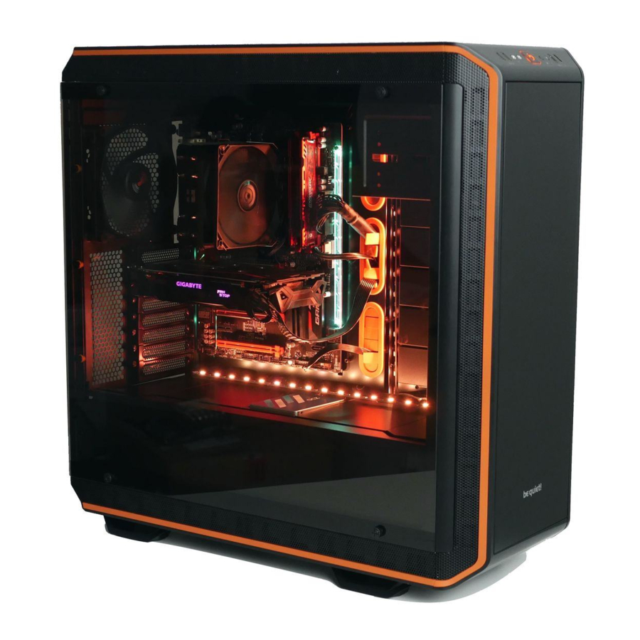
be quiet! Dark Base Pro 900 - PC Cases Manual
- User manual ,
- User manual (96 pages) ,
- User manual (72 pages)
Advertisement
SPECIFICATIONS
| Dimensions (W x H x D in mm) | 243 x 586 x 577 |
| Case type | Full tower |
| Material | 0.8mm – 1mm SECC, 0.8mm aluminum, ABS plastic, 4mm tinted and tempered glass |
| Motherboard compatibility | E-ATX, XL-ATX, ATX, M-ATX, Mini-ITX |
| Front I/O connectors | 2x USB 3.0, 1x USB 3.1 Type C Gen. 2, 1x USB Quick Charging Option, HD audio (microphone + headphones), RGB control switch, HDD status display |
| Fan controller | 8x PWM stepless control / PWM hub |
| Max. CPU cooler height (mm) | 185 |
| Max. graphics card lenght (mm) | 325 / 470 (without HDD bracket) |
| Max. PSU length (mm) | 150 – 284 |
| PCI slots | 8 |
| 5.25" bay | 2 |
| 3.5" bay | 7 (5 ex works) |
| 2.5" bay | 14 (10 ex works) |
| Case fans (mm) / (rpm) | Front: 2x Silent Wings 3 140 / 1,600 | Rear: 1x Silent Wings 3 140 / 1,600 |
| Optional case fans (mm) | Front: 1x 140 (without ODD cage, bracket included) Top: 3x 140 / 4x 120 / 1x 180 | Bottom: 2x 140/120 | PSU shroud: 1x 120 |
| Optional radiator installation (mm) | Front: 120, 140, 240, 280, 360, 420 Top: 120, 140, 180, 240, 280, 360, 420 Rear: 120, 140 |
| Additional features | Wireless charger for Qi enabled devices, switchable multi mode, multi color and expandable RGB LED lightning (white, red, green, blue, orange, purple), supports motherboard LED control |
CONTENTS

EXPLODED VIEW AND DESCRIPTION OF PARTS

| A | Side window of tempered glass | Q | Front I/O panel |
| B | Fastening screws | R | Case body |
| C | ODD cage | S | Floor air filter |
| D | HDD cage | T | Case floor |
| E | PSU mounting | U | Silent Wings 3 fan |
| F | Double HDD slot cover | V | SSD bracket |
| G | HDD slot covers | W | PCB panel |
| H | Rear slot covers | X | Motherboard tray |
| I | Rear PSU shroud | Y | Case front |
| J | HDD panel | Z | ODD covers |
| K | Front of the PSU shroud | ||
| L | SSD bracket | a | Front air filter |
| M | Mounting for PSU shroud | b | Door |
| N | Mounting for PSU shroud | c | Side panel |
| O | Top cover of PSU shroud | d | Filter in the side panel |
| P | Top cover of case | e | 2-stepped opening in the side panel |
Front I/O and media ports

| A | USB 3.0 | F | USB 3.1 Type C Gen. 2 |
| B | HD audio (microphone and audio) | G | Quick charging option |
| C | Power button | H | Stepless fan controller |
| D | LED control switch | I | Qi charging station |
| E | HDD LED |
I/O ports
The front I/O ports that are provided require connections to your motherboard.
HD audio (headphone and microphone sockets)

Determine the HD audio pin connectors on your motherboard and insert the HD audio cables into the sockets allocated there. You will find information about the pin assignment of your motherboard in the motherboard handbook.
USB 3.1 Type C Gen. 2

Locate the USB 3.1 Type C pin connector on your motherboard and attach the USB 3.1 Type C cable using the designated sockets there.
USB 3.0

Find the USB 3.0 pin connectors on your motherboard and plug the USB 3.0 cable into the sockets allocated there. You will find information about the pin assignment of your motherboard in the motherboard handbook.
On/off switch, LED power indicator, HDD activity indicator

The illustrated plug connects the power switch and the case's LED indicators with your motherboard. Take care to use the correct polarity with the LEDs. Your motherboard handbook will provide information on the correct connections.
PCB panel ports

| A | PWM connector to the motherboard |
| B | PWM connector to the fans |
| C | LED connector to the motherboard |
| D | LED output for added external LEDs |
| E | Connector for the supplied LEDs |
| F | Connector for the Qi charger |
| G | SATA power connector |
| H | LED switch connector |
| I | Connection cable for fan controller slider switch |
| J | Switches for choosing between Silence and Performance modes |
Use of fan controller
The fan controller has two modes of operation.

- Automatic operation
In this case the PWM signal of the motherboard is used and the speed of all PWM fans connected is automatically regulated by the motherboard. To enable this the slider switch must be positioned at position "0" completely to the left. For the automatic PWM fan controller to function, a cable must connect port "A" on the PCB panel to the PWM connector on your motherboard. Lacking this connection it is only possible to regulate the speed of the fans connected manually. - Manual control
Whenever the fan controller slider switch is moved rightwards away from its far left position, the PWM signal is ignored and the speed of the fans is manually controlled in a stepless range. In total eight PWM fans can be connected to the fan controller PCB. These eight sockets are divided into two channels (left and right) each with four connections. By setting the switches "J" on the PCB it is possible to choose between Silence and Performance modes independently for both of these channels. According to these switch positions the range of fan speeds possible are 400 – 1,040rpm in Silence mode and 800 – 1,600rpm in Performance mode.
If the slider switch is returned to its starting position "0" on the far left, the PWM signal regains control of fans.
Installation and handling of the LEDs
It is possible to freely position the LED lighting supplied in the case to suit your system setup by affixing and connecting the adhesive strips. The LED strips must be connected to connector "E" on the PCB panel.
Description of the LEDs
The LED lighting included in the scope of delivery is controllable in several modes of color and operation. Connector "D" on the PCB panel can be used to connect additional LED lighting strips up to a maximum of 24 watts for lighting the interior of the case. It is also possible to link the LED strips supplied directly together and in this way extend them.

Only 12V LEDs may be connected.
In manual mode by briefly pressing switch "D" on the front panel it is possible to cycle through the colors. When "breath mode" is enabled there is an intermediate step between each color.
| 1 | White | 8 | Blue breath |
| 2 | White breath | 9 | Orange |
| 3 | Red | 10 | Orange breath |
| 4 | Red breath | 11 | Purple |
| 5 | Green | 12 | Purple breath |
| 6 | Green breath | 13 | Breath mode alternately in all colors |
| 7 | Blue | 14 | LEDs off |
Synchronized operation
To toggle between manual and synchronized operation hold down switch "D" on the front panel for about three seconds.
In synchronized operation, connector "C" on the LED controller PCB is connected to the socket designated for RGB LED on the motherboard. The integrated lighting is then controlled by the motherboard, with the same range of colors.
For information about operation of the LED controller of your motherboard please refer to the motherboard handbook.
Charging station for Qi enabled devices
The preinstalled charging station provides contactless charging of any device that conforms to the Qi standard. If your device (e.g. your smartphone) is so equipped you can charge your device by simply placing it on area "I" on the top of the case, without the need to plug it in.
In so doing, make sure you place the device so that its charge receptor is positioned centrally on charging surface "I".
LAYOUTS
MOTHERBOARD: ATX
HDD slots facing the inside, space for a radiator in front of the HDD cage
MOTHERBOARD: E-ATX
HDD slots facing the outside, space for a large motherboard
Layout A
Windowed side on the left


Layout B
Windowed side on the right


*PCIe slots available / space above the motherboard
 Note: These are just sample configurations. Many alternatives are also possible.
FAN COMPATIBILITY

| Position | Size (mm) |
| Top | 4x 120, 3x 140, 180* |
| Bottom | 2x 120, 2x 140 |
| Front | 3x 120, 3x 140 |
| Rear | 1x 120, 1x 140 |
| PSU shroud | 1x 120 |
RADIATOR SUPPORT

| Position | Size (mm) |
| Top | 120, 140, 180*, 240, 280, 360, 420 |
| Front | 120, 140, 240, 280, 360,420 |
| Rear | 120, 140 |
*Mounting point center to center: 154mm
REMOVING THE SIDE PANELS
Removal of the side window
Unscrew the fastening screws to detach the glass panel.

LED lighting strips can be installed in the upper, front and lower parts of the case.

Removing the air filters
Draw out the lower filter and swing down the front filter.

Remove the air filter from the side panel.

Removing the case front
Open the door and first remove the lower air filter and detach the side window.

Press all hooks on the inside of the case outwards, to release the front.

Now detach the case front from the case body.

Removing the top cover
First remove the case front. Locate the eight hooks under the top cover and press these to the outside, to release the cover.

Lift the cover up to remove it.

Removing the PSU shroud
Please note: To simplify installation or replacement it is recommended you remove the HDD cage.
First remove the screws on the PSU shroud.

Remove the screws on the HDD panel.

Also unfasten the screws holding the PSU shroud on the front side.

Withdraw the PSU shroud and remove it from the case.

Removing the floor of the case and the case feet
First remove the PSU shroud (8.5). Next unscrew the two screws at the bottom of the case.

Press the case towards the front and lift it up to release the case floor.

To remove the feet, unscrew their fastening screws and press them downwards and out.

Changing the side the door opens
Remove the case front and door.

Remove all hinges and magnetic catches from the door.

Remove all hinges and magnetic catches from the door.

Fit these into the openings on the opposite side of the door.

Refit all hinges and magnetic catches on the opposite side of the door.

Refit the case front to the case body.

Removing the ODD cage
First remove the case front and the top cover. Next remove the front I/O module, in order to unfasten the screws holding the ODD cage and remove this.

Install the fan bracket to fit an additional fan on the front.

AFFIXING AND REMOVING DISK DRIVES
Installing a 5.25" drive
Remove the 5.25" cover and slide the 5.25" device into the cage.

Remove the side panel and secure the 5.25" device with knurled-head M3 screws.

Installing drives into the HDD cage
Secure HDDs with four HDD screws into the 3.5" cage.

Two SSDs can be installed into the upper and lower parts of each HDD cage.

It is possible to install two HDDs into the upper and lower parts of the double HDD cage. To secure these please use the screws supplied.

Installing an SSD on the motherboard tray
Detach the SSD bracket on the rear side of the motherboard tray.

Secure the SSD bracket on the SSD.

Installing an SSD on the PSU shroud
First detach the central panel of the PSU shroud.

Fit the SSD to the SSD bracket and secure the drive with M3 screws.

Now place the SSD bracket in position on the PSU shroud.

Affix this using the 6#32 screws.

HDD slot cover
The five HDD slot covers may each be positioned in three ways. They can either completely cover the opening or at two offset distances to suit different cable widths.

As required, the covers can be removed or positioned to organize cables.

To optimize the cable routing, individual segments of each cover can be snapped off.

Any segments that are snapped off cannot be refitted.
MODIFYING THE CASE LAYOUT
Changing the mounting height of the motherboard tray (layouts 3, 4, 5, 6)
Remove the side panel. Unscrew the six screws on the rear side of the motherboard tray (as shown).

Unscrew the three screws on the front side of the motherboard tray (as shown) and detach the motherboard tray.

If you wish, you can now use the motherboard tray as a test bench.

Refit the motherboard tray with the nine screws removed in any one of three possible mounting heights.

Remove covers on the rear side, by removing the fastening screws on both sides.

Reposition the covers on the rear side, so that that they fill any gaps and secure the covers with screws.

Changing the orientation of the HDD panel (layout 2, 4, 6)
Remove the side panels, the case front, the PSU shroud and the motherboard tray.

Remove the double HDD cage. The single HDD cages can be left in place.

Detach the HDD panel by unscrewing its ten screws.

Turn the HDD panel upside down.

Refit the HDD panel and secure it again with the ten screws.

Mounting positions for the power supply
First remove the PSU shroud.

Remove the PSU mounting and reposition the step screws at the bottom of the case.

Fixing points of the step screws for normal layout.

Fixing points of the step screws for inverted layout.

Affix the PSU mounting at the desired layout depth.

It is necessary for inverted layout to remove the PSU shroud on the rear side and refit it rotated through 180 degrees.

Assembling with inverted layout
To install the system on the opposite side of the case, the motherboard tray, HDD panel, PSU shroud and the PSU mounting must all be relocated.

Install the HDD panel on the opposite side of the case.

Remove the rubber decoupling elements from the frame and refit these on the opposite side.

Now reinstall the PSU shroud and the motherboard tray.

INSTALLING THE COMPONENTS
Installing the motherboard
Secure the motherboard with motherboard screws. Standoffs for an ATX motherboard are preinstalled.

Installing the power supply
As a first step, remove the PSU shroud. Next unscrew the screws holding the PSU mounting and detach this.

Affix the mounting to the PSU with screws.

Fit the power cable into the rear of the PSU before positioning the PSU and mounting in the case. Then secure the PSU mounting with its screws.

Installing the PCI / PCIe cards
Unscrew and detach the respective PCI slot covers before attempting to insert PCI / PCIe add-on cards.

Possibilities for liquid cooling
Attach the pump to the LCS bracket provided. To decouple the pump for sound, use the rubber grommets supplied (nuts and bolts are not included).

Position the LCS bracket with fitted pump on the HDD cage and fasten it there.

Installing the LCS cylindrical tank
Install the supporting brackets onto the HDD panel.

Manufacturer's details
Listan GmbH & Co. KG | Biedenkamp 3a | 21509 Glinde | Germany
Visit the contact section on bequiet.com for the right regional service information.
Monday through Friday 09:00 – 17:30 (UTC+1)
Tel. 0049 40 736 7686 - 44 Fax 0049 40-7367686-69
Email: service@bequiet.com
Website: www.bequiet.com
Documents / Resources
References
be quiet! - Silent PSUs, cases and PC cooling products. PSU calculator and cooler check for your PC
be quiet! - Silent PSUs, cases and PC cooling products. PSU calculator and cooler check for your PC
Download manual
Here you can download full pdf version of manual, it may contain additional safety instructions, warranty information, FCC rules, etc.
Advertisement


Need help?
Do you have a question about the Dark Base Pro 900 and is the answer not in the manual?
Questions and answers