
Related Manuals for Leuze MA 255i


Summary of Contents for Leuze MA 255i
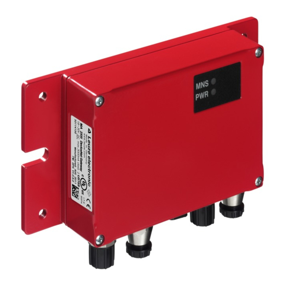
- Page 1 MA 255 Modular interfacing unit for Leuze Ident and RS 232 devices on DeviceNet T E C H N I C A L D E S C R I P T I O N...
- Page 2 Leuze electronic GmbH + Co. KG P.O. Box 1111, D- 73277 Owen Tel. +49(0) 7021/ 573-0, Fax +49(0)7021/ 573-199 info@leuze.de w.leuze.com Sales and Service Germany Sales Region East Sales Region North Sales Region South Phone 035027/629-106 Phone 07021/573-306 Phone 07021/573-307...
-
Page 3: Table Of Contents
Connecting the Leuze device ........ - Page 4 Reading out information in service mode ........41 255i Leuze electronic...
- Page 5 12.6 Setting the read parameters on the Leuze device ......72 12.6.1 Specific feature for the use of hand-held scanners (bar code and 2D devices, combi devices with RFID) .
- Page 6 Disassembling, packing, disposing ......... 82 Specifications for Leuze end devices ..... . 83 16.1...
- Page 7 ASCII table ............99 Leuze electronic...
-
Page 8: General Information
Notice! The Declaration of Conformity for these devices can be requested from the manufacturer. The manufacturer of the product, Leuze electronic GmbH + Co. KG in D-73277 Owen, possesses a certified quality assurance system in accordance with ISO 9001. 255i... -
Page 9: Description Of Functions
255i where a module converts it into the DeviceNet format. The data format on the RS 232 interface corresponds to the Leuze standard data format (9600 bd, 8N1 and STX, data, CR, LF). The integration of the EDS file in the hardware manager of the PLC is necessary to ensure the correct function of the MA 255i. -
Page 10: Definition Of Terms
• Online command: These commands refer to the respective, connected ident device and may be differ- ent depending on the device. These commands are not interpreted by the MA 255i, but are instead transmitted transparently (see description of ident device). -
Page 11: Safety Notices
The MA 255i modular interfacing unit is used for connecting Leuze devices such as bar code- or 2D code readers, hand-held scanners, RFID read-write devices, etc. directly to the fieldbus. A detailed list can be found in "Description of functions" on page 7. -
Page 12: Working Safely
Observe the locally applicable legal regulations and the rules of the employer's liability insurance association. Qualified personnel Mounting, commissioning and maintenance of the device must only be carried out by qualified personnel. Electrical work must be carried out by a certified electrician. 255i Leuze electronic... -
Page 13: Fast Commissioning / Operating Principle
Fast commissioning / operating principle Notice! Below you will find a short description for the initial commissioning of the DeviceNet gateway MA 255i. Detailed explanations for the listed points can be found throughout the handbook. Mounting The gateway mounting plate MA... -
Page 14: Connecting The Leuze Device
Fast commissioning / operating principle 3.3.1 Connecting the Leuze device To connect the Leuze device to the internal RS 232 device interface, open the housing of the MA 255i and guide the corresponding device cable (see chapter 14.7, e.g., KB 031 for BCL 32) through the middle threaded opening. -
Page 15: Setting The Devicenet Baud Rate
Finally, close the housing of the MA 255i. Attention! Only then may the supply voltage be applied. Upon startup of the MA 255i, the device selection switch and the address settings are queried and the gateway automatically sets itself to the Leuze device. Connecting functional earth FE ... -
Page 16: Starting The Device
After all parameters have been set in the planning tool/control, the download to the MA 255i takes place. The set parameters are now stored on the MA 255i. Afterwards, all MA 255i parameters should be stored via upload in the control. This aids in retaining the parameters during device exchanges, as they a re now also stored centrally in the control. -
Page 17: Device Description
With this special operating mode, it is possible to use the first bytes of the data range to transmit predefined commands to the connected device by means of bit activation. For this purpose, device-dependent commands (so-called online commands) are predefined via the device selection switch, see chapter 16 "Specifications for Leuze end devices". Leuze electronic... -
Page 18: Device Construction
Figure 4.1: Connection of a Leuze devices (BCL, RFI, RFM, VR) to the fieldbus The cable of the respective Leuze device is guided through cable bushings with PG cable glands into the MA 255i and connected there with the PCB connectors. -
Page 19: Operating Modes
For fast commissioning, the MA 255i offers an additional operating mode, the "Service mode", in addition to the "Standard mode". In this operating mode, the Leuze device can, for example, be configured on the MA 255i and the communication can be tested on the fieldbus. -
Page 20: Fieldbus Systems
Attention! For the service PC to function, the RS 232 parameters must be the same as those of the MA. The Leuze standard setting of the interface is 9600 bd, 8N1 and STX, data, CR, LF. Fieldbus systems Various product variants of the MA... - Page 21 The limits of network expansion without repeater are specified by the ODVA. The specified limit values are dependent on the design of the data line. A distinction is made between "thick cable", "mid cable" and "thin cable". Leuze electronic 255i...
- Page 22 Max. length of all sub cables per network in m Thick cable =1 Mid cable = 2 Thin cable = 3 The ready-made data lines from Leuze electronic correspond to the thin cable. Communication The gateway MA 255i supports the CIP-based DeviceNet protocol and requires the EDS file (Electronic Data Sheet) for communication;...
-
Page 23: Specifications
Power Collection error Mechanical data Protection class IP 65 (with screwed-on M12 and connected Leuze device) Weight 700 g Dimensions (W x H x D) 130 x 90 x 41 mm / with plate: 180 x 108 x 41 mm... -
Page 24: Dimensioned Drawings
IEC 60068-2-6, test FC Shock IEC 60068-2-27, test Ea Electromagnetic compatibility EN 61000-6-3:2007 (interference emissions for resi- dential, commercial and light-industrial environments) EN 61000-6-2:2005 (interference rejection for indus- trial sectors) Dimensioned drawings Figure 5.1: Dimensioned drawing MA 255 255i Leuze electronic... -
Page 25: Type Overview
Specifications Type overview The following versions of the MA 2xxi gateway family are available for facilitating the integration of Leuze RS 232 devices in the various fieldbus types. Fieldbus Device type Part no. PROFIBUS DP V0 MA 204 50112893 EtherNet TCP/IP... -
Page 26: Installation And Mounting
Save the original packaging for later storage or shipping. If you have any questions concerning your shipment, please contact your supplier or your local Leuze electronic sales office. Observe the applicable local regulations when disposing of the packaging materials. -
Page 27: Mounting
• using four threaded holes (M 6) or • Using two M 8 screws on the two lateral grooves. Fastening by means of four M 6 or two M 8 screws Fastening options Figure 6.2: Fastening options Leuze electronic 255i... -
Page 28: Device Arrangement
• The housing cover should be easily accessible, so that the internal interfaces (device interface for connecting the Leuze device via PCB connectors, service interface) and other operational controls are easy to reach. • Maintaining the required environmental conditions (temperature, humidity). -
Page 29: Electrical Connection
The fieldbus gateways are designed in accordance with safety class III for supply by PELV (protective extra-low voltage with reliable disconnection). Notice! Protection class IP65 is achieved only if the connectors and caps are screwed into place! Leuze electronic 255i... -
Page 30: Electrical Connection
The number and function of the switching inputs/outputs is dependent on the connected end device. An internal RS 232 interface is used for connecting the respective Leuze device. Another internal RS 232 interface functions as a service interface for configuring the connected device via a serial null modem cable. - Page 31 In this case, only the switching input and output on PWR IN are active. The function of the switching inputs and outputs is dependent on the connected Leuze device. Detailed information on this topic can be found in the respective operating instructions.
-
Page 32: Pwr Out Switching Input/Output
(A-coded) Table 7.3: Pin assignments for DeviceNet BUS IN For the host connection of the MA 255i, the ready-made KB DN/CAN-xxxxx-Bx cables are preferred, table 14.5 "Bus connection cable for the MA 255i" on page 80. 255i Leuze electronic... -
Page 33: Bus Out
(A-coded) Table 7.4: Pin assignments for DeviceNet BUS OUT For the host connection of the MA 255i, the ready-made KB DN/CAN-xxxxx-Sx cables are preferred, table 14.5 "Bus connection cable for the MA 255i" on page 80. Notice! Ensure adequate shielding. For the devices and ready-made cables offered by Leuze electronic, the shield is on PIN 1. -
Page 34: Device Interfaces
7.5.1 RS 232 device interface (accessible after opening the device, internal) The device interface is prepared for the system plugs (PCB connectors) for Leuze devices RFI xx, RFM xx, BCL 22 as well as BCL 32, VR with KB 031. -
Page 35: Service Interface (Internal)
Attention! For the service PC to function, the RS 232 parameters must be the same as those of the MA. The Leuze standard setting of the interface is 9600Bd, 8N1 and STX, data, CR, LF. Notice! To configure the devices connected to the external interface, e.g., BCL 8 (JST plug connector "X30"), a cable specially configured for this purpose is necessary. -
Page 36: Status Displays And Operational Controls
LED indicators on the circuit board LED (Status) Device OFF - no operating voltage or device defect continuous green light Device ok - readiness for operation continuous orange light Device error/ firmware available flashing green-orange Device in boot mode - no firmware 255i Leuze electronic... -
Page 37: Led Indicators On The Housing
- no operating voltage or device error continuous green light Device ok - self test successfully finished - ready flashing green Device ok, device in service mode red, flashing Configuration error - baud rate or address incorrect Leuze electronic 255i... -
Page 38: Internal Interfaces And Operational Controls
RS 232 service interface Sub-D Jumper for bridging, separating switching input/output PWR IN/OUT 3 JST plug connectors: connection of the Leuze devices Switch S3 for selecting the baud rate Figure 8.2: Front view: operational controls of the MA 255 255i... - Page 39 Second BUS interface for creating a network with other participants in a linear topology JST plug connector with 12 pins Leuze device Connection of the Leuze devices with 5 V / 1 A (BCL 8, BPS 8 and hand-held scanner) JST plug connector with 10 pins Leuze device Connection of the Leuze devices (BCL, RFI, RFM,…)
-
Page 40: Connector X30
RS 232 interface can be operated. 8.2.3 RS 232 service interface – X33 The X33 RS 232 interface facilitates the configuration of the Leuze device and the MA 255i via PC, which is connected by means of a serial null modem cable. -
Page 41: Rotary Switch S4 For Device Selection
LSIS 122 Reset to factory setting The gateway is set via the switch position on the Leuze device. If the switch position is changed, the device must be restarted, since the switch position is only queried after switching off completely and then restarting the device. -
Page 42: Switch For Address Selection In The Fieldbus
Further information on the respective address ranges and the addressing procedure can be found in chapter 12.1. 8.2.7 Switch for setting the baud rate You can set the baud rate for data transmission with the S3 rotary switch. Position 1-3 Figure 8.7: Rotary switch for setting baud rate 255i Leuze electronic... -
Page 43: Configuration
The respective configuration programs – e.g. for bar code readers the BCL-Config, for RFID devices the RF-Config etc. – and the associated documentation is provided on the Leuze home page in the Download area: www.leuze.de \ download \ identify... - Page 44 COM port settings Notice! Observe that STX, data, CR, LF framing must be set on the PC terminal program so that communication is possible with the connected Leuze device. Commands You can now call up information on the MA 255i by sending the following commands.
- Page 45 Configuration Selected scanner Currently selected Leuze device (selected via switch S4). Gateway mode Transparent or Collective mode. Ring buffer fill level Current fill level of the ring memory in Collective mode (ASCII->Fieldbus). 1024 bytes max. Received ASCII Frames Number of received ASCII frames.
-
Page 46: Telegram
… Only the data part with the corresponding frame (e.g., STX, CR & LF) is then transmitted between the fieldbus gateway and the Leuze end device. The two control bytes are processed by the fieldbus gateway. The corresponding control and status bits and their meaning are specified in section 10.2 and section 10.3. -
Page 47: Description Of The Input Bytes (Status Bytes)
Meaning 0 … 7 DLC0 … DLC7 Data Length Code (length of the following user data) Notice! T-bit means toggle bit, i.e. this bit changes its state on each event ("0" → "1" or "1" → "0"). Leuze electronic 255i... -
Page 48: Detailed Description Of The Bits (Input Byte 0)
The SMA bit is set if the service switch is set to "MA" or 0: Device in "DEV", i.e. if the device is in either fieldbus gateway or Leuze operating mode device service mode. This is also indicated by a flashing PWR 1: Device in service LED on the front side of the device. - Page 49 While the BO bit is set, the RTS sig- 1->0: nal of the serial interface is deactivated. Buffer o.k. The memory size of the gateway for the data of both the PLC and the Leuze end device is 1 kByte. Leuze electronic 255i...
-
Page 50: Detailed Description Of The Bits (Input Byte 1)
Bit no. Designation Meaning Command mode Command mode Broadcast Broadcast (only relevant with a connected MA 3x) 2 … 6 Address 0 .. 4 Address bits 0 .. 4 (only relevant with a connected MA 3x) New data 255i Leuze electronic... -
Page 51: Detailed Description Of The Bits (Output Byte 0)
Command mode This bit is used to activate Command mode. In Command 0: Default, mode, no data is sent by the PLC to the Leuze end device via transparent data Command mode the gateway. In Command mode, various bits that execute... -
Page 52: Detailed Description Of The Bits (Output Byte 1)
Toggle bit: changing this bit causes all data which was copied RS 232 to the transmit buffer of the fieldbus gateway via the CTB bit 1->0: Data to to be transmitted to the RS 232 interface or the connected RS 232 Leuze device. 255i Leuze electronic... -
Page 53: Reset Function / Deleting Memory
OUT data byte 0/parameter byte 0: AAh OUT data byte 1/parameter byte 1: AAh This sets the memory or status/control bits to 00h. Please observe that the data image may need to be updated by toggling in Collective mode. Leuze electronic 255i... -
Page 54: Modes
CTB bit, it goes directly to the RS 232 interface with the set telegram data length. Incomplete (incl. data frame) or faulty telegrams can cause error messages in the connected device! Combination with the Command mode is possible. Data exchange in blocks must be programmed on the PLC. 255i Leuze electronic... -
Page 55: Reading Slave Data In Collective Mode (Gateway -> Plc)
"CTB" bit (Copy to transmit buffer). Please observe that data provided is transmitted directly by toggling the bit. The data is then sent in the order received from the buffer to the connected Leuze device via the serial interface with the command: "SFB" (Send data from transmit buffer). Please don't forget the suitable data frame! Afterward, the buffer is again empty and can be written with new data. - Page 56 RS 232 interface with the set telegram data length. Incomplete (incl. data frame) or faulty telegrams can cause error messages in the connected device! Examples for the activation of a Leuze device In the data part (starting at byte 2) of the telegram to the gateway, a "+" (ASCII) is sent for activation.
- Page 57 All desired data in the (control bit 1.0) buffer? Send data with the SFB = ! SFB toggle bit (control bit 1.2) Command ok? W-ACK = ! W-ACK (status bit 0.0) (Display!) Figure 11.1: Data transmission scheme with long online commands Leuze electronic 255i...
-
Page 58: Command Mode
Leuze end device is to be queried, the corresponding bit is to be set so that a "v" is sent to the Leuze device with the <STX> v <CR> <LF> frame. The Leuze end device also answers the gateway with data (e.g. bar code content, NoRead, device version, etc.) in response to most commands. - Page 59 Modes Examples for the activation of a Leuze device In Command mode, control or output byte 0.0 is to be set for activating the Command mode. Only the corresponding bit (control or output byte 2.1) then needs to be set for activating and deactivating the reading gate.
- Page 60 Figure 11.3: Activating DEV and reading data Notice! Further information on fieldbus telegram structure can be found in chapter 10.1. A specification of all usable commands can be found in chapter "Specifications for Leuze end devices" on page 83. 255i...
-
Page 61: Commissioning And Configuration
Before connecting the supply voltage, recheck all connections and ensure that they have been properly made. The Leuze device must be connected to the internal RS 232 device interface. Connecting the Leuze device Open the housing of the MA 255i and guide the corresponding device cable (e.g., KB 031... - Page 62 Finally, close the housing of the MA 255i. Attention! Only then may the supply voltage be applied. Upon startup of the MA 255i, the device selection switch and the address settings are queried and the gateway automatically sets itself to the Leuze device. PWR IN...
-
Page 63: Starting The Device
After loading, select the device via the device list and enter it into the HW manager via Drag&Drop. Open the input dialog for setting the address and additional parameters by double- clicking on the device symbol and make the desired entries here. Finally, transmit the values to the device via download. Leuze electronic 255i... - Page 64 Commissioning and configuration Figure 12.1: HW manager with inserted MA 255 255i Leuze electronic...
-
Page 65: Installation Of The Eds File
(e.g., RSNetWorx). Notice! You can find the EDS file at: www.leuze.com -> Download -> identify-> Modular interfacing units. If the MA 255i has been assigned an address in the planning tool, the address is to be set... -
Page 66: Eds File - General Info
Each time a connection is established between the control and the MA 255i, these parameters are now transmitted again to the MA 255i. Note that this function must be supported by the control. The DeviceNet baud rate is defined for the entire network in the planning tool/control. The... - Page 67 MA 255i takes place. Leuze electronic recommends activating "Configuration Recovery". This stores all parameters in the control. Notice! In the following tables, all attributes marked in the "Access" column with "Get" in the individual objects are to be understood as inputs of the MA (control).
-
Page 68: Eds File - Detailed Description
Product name (max. 32) SHORT_STRING "MA 255i" In the network configuration (e.g., RSNetWorx), it is possible to specify when entering the individual participants in the scan list which attributes of the scanner are to be monitored from the identity object. - Page 69 ODVA, the MA 255i is assigned number 12 = 0C 12.5.1.3 Product code The product code is an ID assigned by Leuze electronic that has no further impact on other objects. 12.5.1.4 Revision Version number of the identity object. 12.5.1.5 Status The device status is displayed in the status byte, the first part of the telegram.
-
Page 70: Class 15 Parameter Object
Consumed data size Parameter BYTE value Data type UINT 0xC7 Data size Produced data size Parameter BYTE value Data type UINT 0xC7 Data size Serial line mode Parameter BYTE value see below Data type UINT 0xC7 Data size 255i Leuze electronic... - Page 71 Inst. Attr. Parameter BYTE value Data type BYTE Data size 12.5.2.3 Data bytes instance Data display Size Default Data type Access Designation in bit (dec) (dec) (dec) Inst. Attr. Parameter BYTE value Data type BYTE Data size Leuze electronic 255i...
- Page 72 0 = use rotary switch (default) 1 = use EDS settings 12.5.2.8 RS 232 baud rate instance Size Default Data type Access Designation in bit (dec) (dec) (dec) Inst. Attr. Parameter BYTE 1152 value see below Data type UINT 0xC7 Data size 255i Leuze electronic...
- Page 73 12.5.2.11RS 232 stop bits instance Size Default Data type Access Designation in bit (dec) (dec) (dec) Inst. Attr. Parameter BYTE value see below Data type UINT 0xC7 Data size Parameter value: 1 = 1 bit (default) 2 = 2 bits Leuze electronic 255i...
-
Page 74: Setting The Read Parameters On The Leuze Device
The Leuze device is now connected to the fieldbus. Activation of the Leuze device can now occur via the switching input on the MA 255i, via the process data word Out-bit 1 (Bit 0.2) or by transmitting a "+" command to the Leuze device (see chapter 16 "Specifications for Leuze end devices"). -
Page 75: Specific Feature For The Use Of Hand-Held Scanners
When using the MA 255i, the voltage supply of the hand-held scanner (5 V/at 1 A) can be connected to the interface by means of a cable via the 9-pin Sub-D connector (voltage on PIN 9). -
Page 76: Specific Features In The Operation Of An Rfm/Rfi
Each of these (hexadecimal) characters is, in turn, to be handled as an individual ASCII character and converted to hexadecimal format for transmission via the fieldbus. Example: Control byte 0 Control byte 1 Data CHAR Plain text 255i Leuze electronic... -
Page 77: Diagnostics And Troubleshooting
Red, flashing Address >64: no communication Address switch S1, S2, Baud rate >4: no communication . Baud rate selector switch S3. Red continuous light Device error. Send the device to customer service. Table 13.1: General causes of errors Leuze electronic 255i... -
Page 78: Interface Errors
Customer data (please complete) Device type: Company: Contact partner / department: Phone (direct): Fax: Street / No: ZIP code/City: Country: Leuze Service fax number: +49 7021 573 - 199 255i Leuze electronic... -
Page 79: Type Overview And Accessories
KS 095-4A M 12 connector for SW IN/OUT 50040155 KD 01-5-BA M 12 connector, A-coded socket, 5-pin, BUS IN 50040097 KD 01-5-SA M 12 connector, A-coded plug, 5-pin, BUS OUT 50040098 Table 14.3: Connectors for the MA 255 Leuze electronic 255i... -
Page 80: Accessory Ready-Made Cables For Voltage Supply
Thread bare (A-coded) 14.5.2 Specifications of the cables for voltage supply Operating temperature range in rest state: -30° C … +70° C in motion: 5° C … +70° C Material sheathing: PVC Bending radius > 50 mm 255i Leuze electronic... -
Page 81: Order Codes Of The Cables For Voltage Supply
Supply voltage data V+ black Supply voltage data V- DRAIN CAN_H white Data signal CAN_H CAN_L blue Data signal CAN_L M 12 socket (A-coded) BUS IN CAN_H CAN_L Thread Functional earth (housing) DRAIN M 12 connector (A-coded) Leuze electronic 255i... -
Page 82: Specifications Of M 12-Devicenet Connection Cable Kb Dn
M 12 plug + M 12 socket for PROFIBUS, axial connectors, 50114694 cable length 2 m KB DN/CAN-5000-SBA M 12 plug + M 12 socket for PROFIBUS, axial connectors, 50114698 cable length 5 m Table 14.5: Bus connection cable for the MA 255 255i Leuze electronic... -
Page 83: Accessory Ready-Made Cables For Connecting Leuze Ident Devices
Type overview and accessories 14.7 Accessory ready-made cables for connecting Leuze ident devices 14.7.1 Order codes for the device connection cables Type designation Description Part no. KB JST-3000 MA 31, BCL 90, IMRFU-1(RFU), cable length 3 m 50115044 KB JST-HS-300 Hand-held scanner, cable length 0.3 m... -
Page 84: Maintenance
Contact your Leuze distributor or service organization should repairs be required. The addresses can be found on the inside of the cover and on the back. Notice! When sending devices to Leuze electronic for repair, please provide an accurate description of the error. 15.3... -
Page 85: Specifications For Leuze End Devices
0 (control bit 0.0), set the corresponding bit in byte 2. The Leuze end device also responds to most commands by sending data, such as the bar code contents, NoRead, device version, etc., back to the gateway. The answer is not eval- uated by the gateway, but is instead passed on to the PLC. - Page 86 Specifications for Leuze end devices KONTURflex specifications Settings on the MA 255i • DeviceNet address is freely selectable • Device selection switch at position "0" Settings on the DeviceNet • Produced/Consumed data settings: Dependent on number of beams used, but at least "8 bytes in"...
-
Page 87: Bar Code Reader Bcl 8 (S4 Switch Position 1)
Specifications for Leuze end devices 16.2 Bar code reader BCL 8 (S4 switch position 1) Specifications for the serial interface Default parameter BCL 8 Baud rate 9600 Data mode Handshake Protocol framing protocol without acknowledgment Frame <STX> <Data> <CR> <LF>... -
Page 88: Bar Code Reader Bcl 22 (S4 Switch Position 2)
Specifications for Leuze end devices 16.3 Bar code reader BCL 22 (S4 switch position 2) Specifications for the serial interface Default parameter BCL 22 Baud rate 9600 Data mode Handshake Protocol framing protocol without acknowledgment Frame <STX> <Data> <CR> <LF>... -
Page 89: Bar Code Reader Bcl 32 (S4 Switch Position 3)
Specifications for Leuze end devices 16.4 Bar code reader BCL 32 (S4 switch position 3) Specifications for the serial interface Default parameter BCL 32 Baud rate 9600 Data mode Handshake Protocol framing protocol without acknowledgment Frame <STX> <Data> <CR> <LF>... -
Page 90: Bar Code Reader Bcl 300I, Bcl 500I (S4 Switch Position 4)
Specifications for Leuze end devices 16.5 Bar code reader BCL 300i, BCL 500i (S4 switch position 4) Specifications for the serial interface Default parameter BCL 300i, BCL 500i Baud rate 9600 Data mode Handshake Protocol framing protocol without acknowledgment Frame <STX>... -
Page 91: Bar Code Reader Bcl 90 (S4 Switch Position 5)
Specifications for Leuze end devices 16.6 Bar code reader BCL 90 (S4 switch position 5) Specifications for the serial interface Default parameter BCL 90 Baud rate 9600 Data mode Handshake Protocol framing protocol without acknowledgment Frame <STX> <Data> <CR> <LF>... -
Page 92: Lsis 122 (S4 Switch Position 6)
Specifications for Leuze end devices 16.7 LSIS 122 (S4 switch position 6) Specifications for the serial interface Default parameter LSIS 122 Baud rate 9600 Data mode Handshake Protocol framing protocol without acknowledgment Frame <STX> <Data> <CR> <LF> Specifications for Command mode To activate the Command mode, bit 0 must be set to 1 in control byte 0. -
Page 93: Lsis 4X2I (S4 Switch Position 7)
Specifications for Leuze end devices 16.8 LSIS 4x2i (S4 switch position 7) Specifications for the serial interface Default parameter LSIS 4x2i Baud rate 9600 Data mode Handshake Protocol framing protocol without acknowledgment Frame <STX> <Data> <CR> <LF> Specifications for Command mode To activate the Command mode, bit 0 must be set to 1 in control byte 0. -
Page 94: Hand-Held Scanner (S4 Switch Position 8)
Specifications for Leuze end devices 16.9 Hand-held scanner (S4 switch position 8) Specifications for the serial interface Default parameter Hand-held scanner Baud rate 9600 Data mode Handshake Protocol framing protocol without acknowledgment Frame <Data> <CR> <LF> Notice! Command mode cannot be used with hand-held scanners. -
Page 95: Rfi, Rfm, Rfu Rfid Readers (S4 Switch Position 9)
Specifications for Leuze end devices 16.10 RFI, RFM, RFU RFID readers (S4 switch position 9) Specifications for the serial interface Default parameter RFM 12,RFM 32 and RFM 62 RFI 32 RFU (via IMRFU) Baud rate 9600 Data mode Handshake Protocol... -
Page 96: Bps 8 Bar Code Positioning System (S4 Switch Position A)
Specifications for Leuze end devices 16.11 BPS 8 bar code positioning system (S4 switch position A) Specifications for the serial interface Default parameter BPS 8 Baud rate 57600 Data mode Handshake Protocol binary protocol without acknowledgment Frame <Data> Specifications for Command mode To activate the Command mode, bit 0 must be set to 1 in control byte 0. -
Page 97: Ams Distance Measurement Device, Odsl Xx Optical Distance Sensors With Rs 232 Interface (S4 Switch Position B)
Specifications for Leuze end devices 16.12 AMS distance measurement device, ODSL xx optical distance sensors with RS 232 interface (S4 switch position B) Notice! In this switch position, 6-byte data (fixed) is always expected by the device. This is why a quick telegram sequence can be transmitted reliably even without a data frame. - Page 98 Specifications for Leuze end devices ODSL 9, ODSL 30 and ODSL 96B Notice! The default settings of the ODS serial interface have to be adjusted! Further information on configuration of the interface can be found in the technical description of the corresponding device.
-
Page 99: Modular Interfacing Unit Ma 3X (S4 Switch Position C)
Specifications for Leuze end devices 16.13 Modular interfacing unit MA 3x (S4 switch position C) Specifications for the serial interface Default parameter MA 3x Baud rate 9600 Data mode Handshake Protocol framing protocol without acknowledgment Frame <STX> <Data> <CR> <LF>... -
Page 100: Resetting The Parameters (S4 Switch Position F)
Specifications for Leuze end devices 16.14 Resetting the parameters (S4 switch position F) To reset all parameters of the MA that can be configured with software (such as baud rate, IP address, dependent on type) to the factory settings, do the following: ... -
Page 101: Appendix
Record separator UNIT SEPARATOR Unit separator SPACE Space EXCLAMATION POINT Exclamation point " QUOTATION MARK Quotation mark NUMBER SIGN Number sign DOLLAR SIGN Dollar sign PERCENT SIGN Percent sign & AMPERSAND Ampersand APOSTROPHE Apostrophe OPENING PARENTHESIS Opening parenthesis Leuze electronic 255i... - Page 102 Plus sign COMMA Comma HYPHEN (MINUS) Hyphen (minus) PERIOD (DECIMAL) Period (decimal) SLANT Slant COLON Colon SEMICOLON Semicolon < LESS THAN Less than EQUALS Equals > GREATER THAN Greater than QUESTION MARK Question mark COMMERCIAL AT Commercial AT 255i Leuze electronic...
- Page 103 OPENING BRACKET Opening bracket REVERSE SLANT Reverse slant CLOSING BRACKET Closing bracket CIRCUMFLEX Circumflex UNDERSCORE Underscore ‘ GRAVE ACCENT Grave accent OPENING BRACE Opening brace VERTICAL LINE Vertical line CLOSING BRACE Closing brace TILDE Tilde DELETE (RUBOUT) Delete Leuze electronic 255i...
- Page 104 LED status indicators ....34 Connecting the Leuze device ... 12 Leuze device PCB connectors X30 …...
- Page 105 Output bytes ..... . 48 Service Leuze device ....17 Transparent mode .
Need help?
Do you have a question about the MA 255i and is the answer not in the manual?
Questions and answers