Advertisement
Quick Links
de
Gesamtanleitung
en
General instructions
fr
Instructions générales
sv
Instruktioner
nl
Algemene instructies
it
Istruzioni generali
fi
Yleisohjeet
es
Instrucciones generales
da
Install.- og monteringsvejl.
de
Montageort
Kapillarrohr in Luftrichtung nach dem ersten wassergefüllten und
frostgefährdeten Lufterwärmer installieren.
Montage
Vor der Montage des Frostfühlers, den Gehäusedeckel durch Lösen
der Befestigungsschraube abnehmen und die M16-Verschraubung
einsetzen, siehe Abb. 1.
• Direktmontage auf die Kanal- oder Gerätewand
− Gummizapfen (4 109 2106 0) in Gehäuserückseite einsetzen,
siehe Abb. 2
− Gehäuse montieren, siehe Abb. 5
• Direktmontage auf die Kanal- oder Gerätewand mit
Testschlaufe für Funktionstest, siehe Abb. 6
Hinweis: Die Temperatur an der Testschlaufe muss gleich oder
höher der Temperatur im Kanal sein!
• Montage mit Montageflansch AQM63.0, für Luftkanäle mit
Isolierungen bis 70 mm Wandstärke, siehe Abb. 3
• Kapillarrohrmontage im Luftkanal mittels Zubehör AQM63.2,
siehe Abb. 4
− Das Kapillarrohr darf an den Wänden nicht scheuern (genügend
Distanzhalter verwenden)
− Mindestabstand von der Kanalwand: ca. 50 mm
− Das Kapillarrohr darf nicht geknickt werden; möglichst großer
− Biegeradius
Elektrische Installation
• Die örtlichen Vorschriften sind zu beachten
• Verdrahtung nach Anlagenschaltplan ausführen
Inbetriebnahme
• Verdrahtung nach Anlagenschaltplan überprüfen
• Es sind keine Einstellungen notwendig
Funktionskontrolle
• Funktionstestschlaufe, oder ein anderes mindestens 250 mm
langes Stück Kapillarrohr, mit Eiswasser auf 0 °C abkühlen,
siehe Abb. 7
• Die Signalspannung, gemessen über die Klemmen B und M, muss
DC 0 V betragen (Messbereich: DC 0...10 V
Siemens Building Technologies / HVAC Products
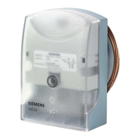
Frostfühler
Frost Sensor
Sonde antigel
Frysgivare
Vorstbeveiliging
Regolatore antigelo
Jäätymissuoja-anturi
Regulator anti-hielo
Frostføler
4 109 2106 0
M16
DIN 7981-
St 4,2 x 22 - C
2 x
0...15 °C)
AQM63.0
en
Mounting location
Install capillary tube downstream from the first hot water heating coil
that may be exposed to frost.
Installation
Before installing the frost detector, remove the housing cover by
loosening the fixing screw and fit the M16 cable gland
(refer to Fig. 1)
• Direct installation on the duct or equipment wall
− Fit rubber (4 109 2106 0) grommet to the rear of the housing
(see Fig. 2)
− Install the housing (see Fig. 5)
• Direct installation on the duct or equipment wall with test loop
for functional test (see Fig. 6)
Note: the temperature at the test loop must be the same as or
higher than the temperature in the air duct!
• Installation with mounting flange AQM63.0, for air ducts with
insulation up to 70 mm (see Fig. 3)
• Installation of capillary tube in air duct by means of AQM63.2
accessory (see Fig. 4)
− The capillary tube should not get into contact with the walls
(use an adequate number of spacers)
− Minimum clearance from duct wall: approx. 50 mm
− The capillary tube must not be sharply bent; the bending radius
should be as large as possible
Electrical installation
• The local regulations must be complied with
• Make wiring according to the plant connection diagram
Commissioning
• Check wiring against the plant connection diagram
• No settings are required
Functional test
• Use ice water to cool the function test loop or another piece of
capillary tube of at least 250 mm length down to 0 °C (see Fig. 7)
• The signal voltage, measured across terminals B and M, must be
DC 0 V (measuring range: DC 0...10 V
4 319 2618 0 c
4 319 2618 0
QAF63...
AQM63.2
QAF63.2: 1 x AQM63.2
QAF63.6: 2 x AQM63.2
0...15 °C)
CM1G1821X
10.08.2005
G1821
3 x
3 x
1/6
Advertisement

Related Manuals for Siemens QAF63 Series


Summary of Contents for Siemens QAF63 Series
- Page 1 • The signal voltage, measured across terminals B and M, must be 0...15 °C) 0...15 °C) DC 0 V (measuring range: DC 0...10 V DC 0 V betragen (Messbereich: DC 0...10 V Siemens Building Technologies / HVAC Products 4 319 2618 0 c CM1G1821X 10.08.2005...
-
Page 2: Montage
− minima distanza dalle lamelle della batteria: circa 50 mm − il capillare non deve avere angoli acuti, eseguire raggi di curva- Idrifttagning tura uniformi e più ampi possibili. Kontrollera den elektriska inkopplingen enligt kopplingsschemat. Siemens Building Technologies / HVAC Products 4 319 2618 0 c CM1G1821X 10.08.2005... -
Page 3: Montaje
• Montaje directo en el conducto o en la pared del equipo con bucle de control de funcioonamiento (ver Fig. 6) Nota: la temperatura del bucle debe ser igual o superior que la temperatua del conducto! Siemens Building Technologies / HVAC Products 4 319 2618 0 c CM1G1821X 10.08.2005... - Page 4 4 109 2106 0 DIN 7981-St 4,2 x 22 DIN 7981-St 4,2 x 22 DIN 7981-St 5,5 x 13 4 109 2106 0 AQM63.0 AQM63.2 0 °C Siemens Building Technologies / HVAC Products 4 319 2618 0 c CM1G1821X 10.08.2005...
- Page 5 4 109 2106 0 DIN 7981-St 4,2 x 22 DIN 7981-St 4,2 x 22 DIN 7981-St 5,5 x 13 4 109 2106 0 AQM63.0 AQM63.2 0 °C Siemens Building Technologies / HVAC Products 4 319 2618 0 c CM1G1821X 10.08.2005...
- Page 6 Mått i mm Maten in mm Dimensioni in mm Mitat mm Type max. min. Dimensiones en mm QAF63.2 2000 Mål i mm QAF63.6 6000 © 2005 Siemens Switzerland Ltd. Siemens Building Technologies / HVAC Products 4 319 2618 0 c CM1G1821X 10.08.2005...
Need help?
Do you have a question about the QAF63 Series and is the answer not in the manual?
Questions and answers