
Related Manuals for Siemens QSA2700D


Summary of Contents for Siemens QSA2700D
- Page 1 QSA2700D / QSA2700 / AQS2700 Fine dust room sensor Basic Documentation A6V11160936_en--_c Smart Infrastructure 2019-04-10...
-
Page 2: Table Of Contents
Initial setup (QSA2700D) ................19 Change settings..................21 4.7.1 Change language (QSA2700D) ........... 21 4.7.2 Change Air Quality Index class (QSA2700D)....... 22 4.7.3 Change display format (QSA2700D) ........... 23 4.7.4 Change theme (QSA2700D) ............25 Analog output range selection (QSA2700D) ..........25 Modbus configuration (QSA2700D) ............ - Page 3 Maintenance ..................33 Replacing AQS2700 ..................33 Proximity sensor (QSA2700D) ..............34 Troubleshooting ..................35 Disposal ....................35 Air Quality Index classes ..............36 Standard compliance ................37 Appendices ..................38 Cyber security disclaimer ................38 A6V11160936_en--_c 3 | 40...
-
Page 5: About This Document
If you find any lack of clarity while using this document, or if you have any criticisms or suggestions, please contact your local point of contact (POC) at the nearest branch office. Addresses for Siemens RCs are available at www.siemens.com/sbt. Conventions for text... - Page 6 From the support team at headquarters fieldsupport-zug.ch.sbt@siemens.com if no local POC is available. Siemens assumes no liability to the extent allowed under the law for any losses resulting from a failure to comply with the aforementioned points or for the improper compliance of the same.
-
Page 7: Product Overview
The fine dust room sensor is designed to measure and transmit indoor concentrations of PM2.5 and PM10. This wall-mounted product has variants with or without displays and can connect directly to Siemens BT controllers as well as many third party controllers via voltage output or Modbus. -
Page 8: Device Overview
Product overview Device overview 2.4 Device overview Hole for wiring (top) for surface mounting 2 [QSA2700 only] 3 [QSA2700D only] LCD display (power supply for display only) 5 [QSA2700D only] Proximity sensor Push button Hole for wiring (bottom) for surface mounting... -
Page 9: Normal Display Overview Of Qsa2700D
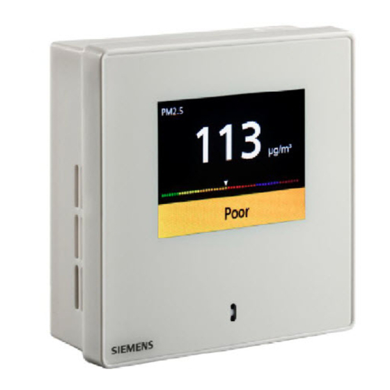
Product overview Normal display overview of QSA2700D 2.5 Normal display overview of QSA2700D PM2.5 in μg/m PM2.5 & PM10 in μg/m PM2.5 & PM10 in μg/m 24 hours trend PM2.5 & PM10 in μg/m and particles/m 1 PM2.5 value in μg/m 2 The current Air Quality Index category 3 PM2.5 trend in rolling 24 hours... -
Page 10: Installation
Installation Mounting requirements 3 Installation 3.1 Mounting requirements Mounting position ● The sensor is suitable for conduit box mounting, dry wall mounting (with mounting hole for wires concealed) and surface mounting. ● The recommended height is 1.2-1.5 m above the floor, especially for type with display. -
Page 11: Wiring
Installation Wiring Mounting dimensions Mounting tools ● Wire stripper ● Screw driver ● Pencil, level & drill (for dry wall mounting and surface mounting only) Wire specification Wires for Specifications Power supply 0.4 to 1.5 mm Analog output 0.4 to 1.5 mm Modbus output Twisted pair 0.4 to 1.5 mm Length <600m... -
Page 12: Installation
Installation Installation 3.3 Installation 1. Separate the housing from the mounting plate using a screw driver. 2. Screw and fix the mounting plate on a conduit box (Conduit box mounting), or on a wall (Dry wall mounting if there is a mounting hole and the wires are concealed in the hole;... - Page 13 Installation Installation 3. Connect and screw wires correctly to the terminal. For surface mounting, you must break out the wiring hole at the top or bottom first. 4. Attach the housing to the mounting plate at the top and then snap on the housing at the bottom.
-
Page 14: Configurations
Configurations Modbus configuration parameters 4 Configurations 4.1 Modbus configuration parameters The sensor is a Modbus (RS485) slave device, configurable via a Modbus master. Name Range / Enumeration Default Configurable Address 1...247 Baud rate (bps) 1 = 9600 / 2 = 19200/ 19200 3 = 38400 / 4 = 57600 Transmission format... -
Page 15: Modbus Registers (Software Version 1.3.13)
Configurations Modbus registers (Software version 1.3.13) Holding Name Description Default Register (16-bit) Modbus address 1…247 R / W Baud rate 1= 9600bps; R / W 2 = 19200bps; 3 = 38400bps; 4 = 57600bps 0 = 1-8-E-1; R / W Transmission format (start bit –... - Page 16 Configurations Modbus registers (Software version 1.3.13) Holding Name Description Default Register (16-bit) No. Number of particles In pcs for particle PM1.0…PM2.5 size between 1.0…2.5 micron Number of particles In pcs for particle PM2.5…PM5.0 size between 2.5…5.0 micron Sensor working status 0: Normal;...
- Page 17 Configurations Modbus registers (Software version 1.3.13) Remarks: ● The register number is counted from 1. ● The precondition for valid displays of temperature (register 217) and r.h. (register 218) is as below: – Register 221 is enabled. – Display value “PM2.5 & PM10 in μg/m ”...
-
Page 18: Push Button Configuration (Qsa2700)
4.4 Push button configuration (QSA2700) 4.4.1 On-event addressing (Climatix controllers configuration) On-event addressing is a rapid configuration approach working together with Siemens Climatix controllers. The sensor is wired and connected to the Climatix controller via Modbus. Enter addressing mode and... -
Page 19: Reset Modbus Parameter
Flashing (0.5 s on / 0. 5 s off) Error 2, communication error Red / yellow Flashing (0.5 s red / 0. 5 s yellow) Possible inaccurate measurement 4.6 Initial setup (QSA2700D) In the following steps: short press short press ●... - Page 20 Configurations Initial setup (QSA2700D) Step Description Picture Power on the device: Page 1 is displayed. page 1 Then in Short press to select the language. Long press (>2 s) to save the selection and page 2 then enter next page (...
-
Page 21: Change Settings
● means the push button long press long press ● (>2 s) means the push button (2…10 s) 4.7.1 Change language (QSA2700D) Step Description Picture page 4 short press page 5. From to enter page 5... -
Page 22: Change Air Quality Index Class (Qsa2700D)
Configurations Change settings 4.7.2 Change Air Quality Index class (QSA2700D) Step Description Picture page 5 short press page 6. From to enter Then in page 6: ● Short press to enter next page ( page 7 ● Long press (>2 s) to enter page 6-1. -
Page 23: Change Display Format (Qsa2700D)
Configurations Change settings 4.7.3 Change display format (QSA2700D) Step Description Picture page 6 short press page 7. From to enter Then in page 7 ● Short press to enter next page ( page 8 ● Long press (>2 s) to enter page 7-1. - Page 24 Configurations Change settings Step Description Picture Page 10 Page 11 Page 12 24 | 40 A6V11160936_en--_c...
-
Page 25: Change Theme (Qsa2700D)
Short press to select a theme color. Long press (>2 s) to save the selection and back to page 8 Page 8-1 4.8 Analog output range selection (QSA2700D) In the following steps: short press short press ● means the push button... -
Page 26: Modbus Configuration (Qsa2700D)
(>2 s) to enter Page 3 page 13, short press page 14. From to enter For Modbus configuration, refer to Modbus configuration (QSA2700D) [➙ 26]. Page 13 page 14 Short press page 3 ● to enter next page ( Long press page 14-1. - Page 27 When “Modify Modbus settings” is selected, press (>2 s) to activate the function. For detailed operation, refer to Modify Modbus settings (QSA2700D) [➙ 28]. Page 15 When “Configure via Climatix” is selected, long press (5…10 s) to activate the function.
-
Page 28: Modify Modbus Settings (Qsa2700D)
Modbus configuration (QSA2700D) Step Description Picture long When “Reset Modbus Settings” is selected, press (>10 s) to activate the function. Page 15-2 4.9.1 Modify Modbus settings (QSA2700D) Step Description Picture page 15 long press page From (>2 s) to enter... - Page 29 Configurations Modbus configuration (QSA2700D) Step Description Picture page 16 short press page 17 From to enter page 17 Then in Short press page 18 ● to enter next page ( Long press page 17-1 ● (>2 s) to enter Page 17...
- Page 30 Configurations Modbus configuration (QSA2700D) Step Description Picture page 18-1, Short press ● to change the values for first digital. ● Long press (>2 s) to save the change and back to page 18 Tip: Only 0, 1, and 2 are available for first digital.
-
Page 31: Technical Data
Technical data Power supply 5 Technical data 5.1 Power supply Operating voltage AC 24 V ±20% / DC 13.5…35 V Frequency 50/60 Hz @ AC 24 V Power consumption 4 VA 5.2 Functional data for PM2.5 Measuring range (selectable) ● 0…500 μg/m ●... -
Page 32: Operation Conditions
Electromagnetic compatibility CE standard EN 60730-1 Immunity EN 61 000-6-2 Emissions EN 61 000-6-3 EU conformity declaration A6V11277342 *) *) The document can be downloaded at http://siemens.com/bt/download. 5.9 General data Color White Weight 140 g 5.10 Display (QSA2700D) Screen Color, no touch Working status Only active when people in front within 1 m (±10%);... -
Page 33: Maintenance
Maintenance Replacing AQS2700 6 Maintenance 6.1 Replacing AQS2700 Replace the sensor module due to: ● Reaching its end of lifetime: as indicated via LED or LCD, and output signal. Refer to Troubleshooting [➙ 35] for the indication. ● The measurement is not as accurate as specified. The sensor still works but is indicated via LED or LCD. -
Page 34: Proximity Sensor (Qsa2700D)
If not possible, insert a new sensor module 10 s after the old one is removed. 6.2 Proximity sensor (QSA2700D) QSA2700D includes a built-in proximity sensor and enters into energy efficient mode if no obstacle is detected in front of the sensor (approximately 1 m) over the past few minutes. -
Page 35: Troubleshooting
Maintenance Troubleshooting 6.3 Troubleshooting Error Description 0-10 V output Modbus QSA2700D Replace sensor module Present 0 V (2 Value of register when: s) and 10 V (2 209 changes s) one by one in from 0 to 1 it is broken;... -
Page 36: Air Quality Index Classes
) and China (1…35 μg/m These different conversions of PM2.5 to AQI, country by country, are reflected by different AQI classes. The sensor QSA2700D for PM2.5 recognizes three different classes that can be selected during product commissioning: ● Class I – U.S. -
Page 37: Standard Compliance
Standard compliance 8 Standard compliance 1. The product complies with CE standard (EN 61000-6-2, EN 61000-6-3, EN 60730-1). 2. The product complies with the RoHS and RoHS CN standard. A6V11160936_en--_c 37 | 40... -
Page 38: Appendices
In order to protect plants, systems, machines and networks against cyber threats, it is necessary to implement – and continuously maintain – a holistic, state-of-the-art security concept. Siemens’ portfolio only forms one element of such a concept. You are responsible for preventing unauthorized access to your plants, systems,... - Page 39 Appendices Cyber security disclaimer A6V11160936_en--_c 39 | 40...
- Page 40 © Siemens Switzerland Ltd, 2017 Issued by Siemens Switzerland Ltd Technical specifications and availability subject to change without notice. Smart Infrastructure Global Headquarters Theilerstrasse 1a CH-6300 Zug +41 58 724 2424 www.siemens.com/buildingtechnologies A6V11160936_en--_c...
Need help?
Do you have a question about the QSA2700D and is the answer not in the manual?
Questions and answers