Carrier 40VMU Series Installation And Maintenance Instructions Manual
Under ceiling/floor indoor unit for variable refrigerant flow (vrf) systems
Hide thumbs
Also See for 40VMU Series:
- Installation and operating instructions (2 pages) ,
- Installation and operating instructions manual (12 pages)
Table of Contents
Advertisement
Quick Links
Installation and Maintenance Instructions
CONTENTS
SAFETY CONSIDERATIONS . . . . . . . . . . . . . . . . . . . 1
GENERAL . . . . . . . . . . . . . . . . . . . . . . . . . . . . . . . . . . . 2
INSTALLATION . . . . . . . . . . . . . . . . . . . . . . . . . . . . . . . 5
Step 1 - Unpack and Inspect Units . . . . . . . . . . . . 5
Step 2 - Position the Unit . . . . . . . . . . . . . . . . . . . . 5
Step 3 - Mount the Unit . . . . . . . . . . . . . . . . . . . . . . 6
Step 4 - Connect Piping . . . . . . . . . . . . . . . . . . . . . . 7
Step 5 - Complete Electrical Connections . . . . . . 8
Step 6 - Position and Connect Controller . . . . . 10
ACB (Auxiliary Control Board) Interface . . . . . . . 13
START-UP . . . . . . . . . . . . . . . . . . . . . . . . . . . . . . . . 13
Pre-Start Check . . . . . . . . . . . . . . . . . . . . . . . . . . . . . 13
System Operation Check . . . . . . . . . . . . . . . . . . . . 13
MAINTENANCE. . . . . . . . . . . . . . . . . . . . . . . . . . . . . . 13
INDOOR UNIT ADDRESSING . . . . . . . . . . . . . . . . 13
Wireless Remote Controller (40VM900001) . . . . . 14
Non-Programmable Controller . . . . . . . . . . . . . . . 14
Programmable Controller . . . . . . . . . . . . . . . . . . . 14
TROUBLESHOOTING . . . . . . . . . . . . . . . . . . . . . . . . 15
Replacement Parts . . . . . . . . . . . . . . . . . . . . . . . . . . 16
APPENDIX A - DIP SWITCH SETTINGS . . . . . . . . 17
SAFETY CONSIDERATIONS
Improper
installation,
adjustment,
maintenance, or use can cause explosion, fire, electrical shock,
or other conditions that may cause death, personal injury or
property damage. The qualified installer or agency must use
factory-authorized kits or accessories when modifying this
product.
Follow all safety codes. Wear safety glasses, protective
clothing, and work gloves. Use quenching cloth for brazing
operations. Have fire extinguisher available. Read these
instructions thoroughly and follow all warnings or cautions
included in literature and attached to the unit. Consult local
building codes and the current editions of the National
Electrical Code (NEC) ANSI/NFPA (American National
Standards Institute/National Fire Protection Association) 70. In
Canada, refer to the current editions of the Canadian Electrical
Code CSA (Canadian Standards Association) C22.1.
Understand the signal words -
.
identifies the most serious hazards,
CAUTION
DANGER
which will result in severe personal injury or death.
WARNING signifies hazards that could result in personal
injury or death. CAUTION is used to identify unsafe practices,
which would result in minor personal injury or product and
property damage.
Manufacturer reserves the right to discontinue, or change at any time, specifications or designs without notice and without incurring obligations.
Catalog No. 20-40VMU001-02
Page
alteration,
service,
,
, and
DANGER
WARNING
Printed in U.S.A.
Form 40VMU-2SI
Under Ceiling/Floor Indoor Unit for
Variable Refrigerant Flow (VRF) Systems
Recognize safety information. This is the safety-alert
symbol ( ). When this symbol is displayed on the unit and in
instructions or manuals, be alert to the potential for personal
injury. Installing, starting up, and servicing equipment can be
hazardous due to system pressure, electrical components, and
equipment location.
Electrical shock can cause personal injury and death. Shut
off all power to this equipment during installation. There
may be more than one disconnect switch. Tag all
disconnect locations to alert others not to restore power
until work is completed.
When installing the equipment in a small space, provide
adequate measures to avoid refrigerant concentration
exceeding safety limits due to refrigerant leak. In case of
refrigerant leak during installation, ventilate the space
immediately. Failure to follow this procedure may lead to
personal injury.
DO NOT USE TORCH to remove any component. System
contains oil and refrigerant under pressure.
To remove a component, wear protective gloves and
goggles and proceed as follows:
a. Shut off electrical power to unit.
b. Recover refrigerant to relieve all pressure from
system using high-pressure and low pressure ports.
c. Traces of vapor should be displaced with nitrogen
and work area should be well ventilated. Refrigerant
in contact with an open flame produces toxic gases.
d. Cut component connection tubing with tubing cutter
and remove component from unit. Use a pan to catch
any oil that may come out of the lines and as a gage
for how much oil to add to the system.
e. Carefully unsweat remaining tubing stubs when
necessary. Oil can ignite when exposed to torch
flame.
Failure to follow these procedures may result in personal
injury or death.
Pg 1
40VMU012-048
WARNING
WARNING
WARNING
02-20
Replaces: 40VMU-1SI
Advertisement
Table of Contents

Related Manuals for Carrier 40VMU Series


Summary of Contents for Carrier 40VMU Series
-
Page 1: Table Of Contents
40VMU012-048 Under Ceiling/Floor Indoor Unit for Variable Refrigerant Flow (VRF) Systems Installation and Maintenance Instructions CONTENTS Recognize safety information. This is the safety-alert symbol ( ). When this symbol is displayed on the unit and in Page instructions or manuals, be alert to the potential for personal SAFETY CONSIDERATIONS . -
Page 2: General
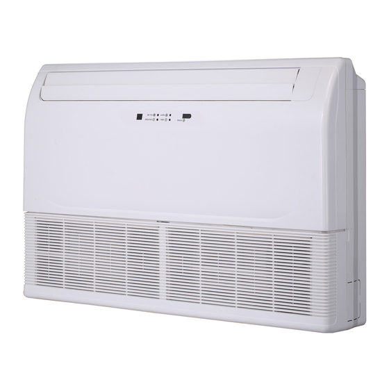
GENERAL CAUTION The 40VMU under ceiling/floor unit can be installed exposed at the ceiling or mounted on the wall close to the floor. It is DO NOT re-use compressor oil or any oil that has been ideal for corner or low-ceiling areas where soffit space is not exposed to the atmosphere. - Page 3 U 012 Voltage (V-Ph-Hz) 3 — 208/230-1-60 Equipment Type — Indoor Unit Blank Product Type VM — VRF Capacity (Btuh) 030 — 30,000 012 — 12,000 015 — 15,000 036 — 36,000 Model Type 018 — 18,000 048 — 48,000 —...
- Page 4 DIMENSIONS DIMENSION (in.) 40VMU UNIT SIZE 012-024 NOTE: All dimensions shown in inches. Fig. 2 —40VMU012-030 Dimensions a40-1857 NOTE: All dimensions shown in inches. Fig. 3 —40VMU036,048 Dimensions...
-
Page 5: Installation
INSTALLATION • Check all tags on the unit to determine if shipping screws are to be removed. Remove screws as directed. Step 1 — Unpack and Inspect Units — Units are • Rotate the fan wheel by hand to ensure that the fan can packaged for shipment to avoid damage during normal transit rotate freely. -
Page 6: Step 3 - Mount The Unit
Table 3 —Unit Weight and Mounting Dimensions (Under Ceiling Mount) OBSTRUCTION OBSTRUCTION DIMENSION (in.) 40VMU UNIT WEIGHT (lb) 015-024 24 in. 24 in. min. min. 036,048 MOUNTING UNIT (UNDER CEILING MOUNT) — The unit can now be lifted on to the hanging rods for under ceiling mounting. -
Page 7: Step 4 - Connect Piping
INSTALLING MOUNTING BRACKET AND MOUNT-ING For models 036 and 048 there is an outside air opening on the UNIT (FLOOR STANDING) — The mounting bracket (see back of the unit. See Fig. 12 below. Fig. 10) can be anchored to the wall with screws. For unit weight and mounting dimensions, see Table 4. -
Page 8: Step 5 - Complete Electrical Connections
• Use a torque wrench for flare nuts. Refer to Table 5 for editions. Units must be electrically grounded in conformance flare nut torque recommendations. with the code. In Canada, wiring must comply with CSA C22.1, Electrical Code. Table 5 — Flare Nut Torque Recommendations WARNING OUTSIDE DIAMETER (IN.) RECOMMENDED TORQUE (FT-LB) - Page 9 LEGEND — Auxiliary Control Board ALARM — Warning Lamp (Optional) AUXH — Output for Auxiliary Heat — Condensate Switch (Optional) CTON — Output for Cooling Operation — Electronic Expansion Valve — Output for Fan Operation — Indoor Fan Motor HTON —...
-
Page 10: Step 6 - Position And Connect Controller
See Fig. 16. Fig. 20 —Connecting the Communication Wires If it is not possible to buy communication wires from Carrier, connect the indoor unit side of communication wires using the connector provided with the accessories as shown in Fig. 21. - Page 11 wired controller outdoor unit Centralized controller NOTE: 24 v. DC Power (Field Supplied) HA HB Indoor unit 1# To No.1 indoor To No.2 indoor Indoor unit 2# Main MDC unit To outdoor To No.3 indoor To No.4 indoor To Sub MDC Indoor unit 3# Indoor unit 4# wired controller...
- Page 12 Touch screen wired controller outdoor unit Centralized controller NOTE: 24 v. DC Power (Field Supplied) HA HB Indoor unit 1# Indoor unit 2# Indoor unit 3# Indoor unit 4# wired controller NOTE: Power from IDU HA HB Indoor unit 5# Network Resistor Indoor unit 6# Maximum wiring length...
-
Page 13: Acb (Auxiliary Control Board) Interface
c. Swing mode of air louvers is working (if applicable to unit). IMPORTANT: The system can connect 64 indoor units, d. Drain pump operation is normal (if applicable). with different system addresses. If two indoor units in the same system have identical addresses, abnormal operation e. -
Page 14: Wireless Remote Controller (40Vm900001)
Wireless Remote Controller (40VM900001) — Indoor unit addressing can be performed using the wireless remote controller. When using the wireless controller, the user must maintain a line of sight with the receiver on the indoor unit. See Fig. 25 for a description of the buttons on the wireless remote. -
Page 15: Troubleshooting
TROUBLESHOOTING Figure 30 shows the LED display panel. See Table 8 for a summary of display indicators. Table 9 lists problems, possible causes, and possible solutions. DEFROST/ ALARM LIGHT FAN LIGHT a40-1878 TIMER LIGHT INFO BUTTON OPERATION LIGHT Fig. 30 —40VMU Display Panel Table 8 —... -
Page 16: Replacement Parts
208/230V-1Ph-60Hz MINIMUM CIRCUIT AMPACITY 0.44 A MAX FUSE OR HACR BREAKER 15 A 0.35 A FAN MOTOR OUTPUT 100W (1/6HP) REFRIGERANT R410A HIGH 580 PSIG DESIGN PRESSURE 320 PSIG SERIAL NO. 1616V00001 Carrier Corporation Fig. 31 —Unit Serial Plate (Example) -
Page 17: Appendix A - Dip Switch Settings
APPENDIX A — DIP SWITCH SETTINGS There are two DIP switches on the main board. Figures A and B show the settings for each parameter controlled by a switch. Switches are shown in the default settings. 1 2 3 4 a40-1925 a40-1923 POSITION 1, 2 —... - Page 18 © Carrier Corporation 2020 Manufacturer reserves the right to discontinue, or change at any time, specifications or designs without notice and without incurring obligations. Catalog No. 20-40VMU001-02 Printed in U.S.A. Form 40VMU-2SI Pg 18 02-20 Replaces: 40VMU-1SI...
Need help?
Do you have a question about the 40VMU Series and is the answer not in the manual?
Questions and answers