Carrier 40VM Series Service Manual
Indoor units and controllers for variable refrigerant flow (vrf) heat pump system
Hide thumbs
Also See for 40VM Series:
- Installation and operating instructions manual (14 pages) ,
- Installation and operating instructions manual (10 pages) ,
- Installation and operating instructions manual (12 pages)
Table of Contents
Advertisement
40VM Series
Indoor Units and Controllers for
Variable Refrigerant Flow (VRF) Heat Pump System
Service Manual
Manufacturer reserves the right to discontinue, or change at any time, specifications or designs without notice and without incurring obligations.
Catalog No. 19-40VM001-06
Printed in U.S.A.
Form 40VM-1SM
Pg 1
8-19
Replaces: New
Advertisement
Table of Contents
Troubleshooting

Subscribe to Our Youtube Channel
Related Manuals for Carrier 40VM Series


Summary of Contents for Carrier 40VM Series
-
Page 1: Service Manual
40VM Series Indoor Units and Controllers for Variable Refrigerant Flow (VRF) Heat Pump System Service Manual Manufacturer reserves the right to discontinue, or change at any time, specifications or designs without notice and without incurring obligations. Catalog No. 19-40VM001-06 Printed in U.S.A. -
Page 2: Table Of Contents
TABLE OF CONTENTS INDOOR UNITS....................................3 General Information..................................3 Refrigerant Circuit..................................5 Operating Temperature Range...............................6 Function and Control..................................7 REMOTE CONTROLLERS................................23 Wireless Remote Controller.................................23 Address Setting....................................24 Wired Remote Controller................................25 TROUBLESHOOTING...................................38 Error Code List....................................38 Wiring Diagrams..................................39 Indoor Electric Control Box Details............................50 Indoor Main Board Instructions..............................58 Troubleshooting from Indoor Unit...............................64 Troubleshooting from Remote Controller............................75 APPENDIX......................................79... -
Page 3: Indoor Units
INDOOR UNIT MODEL NUMBER NOMENCLATURE Digit # 1,2: Product Series 40 - Indoor Fan Coil Unit Digit # 3,4: Model Letters VM - Carrier VRF Digit # 12: Electrical 3 - 208/230-1-60 Digit # 5: Model Number Modifier A - Outside Air... - Page 4 INDOOR UNITS LINEUP Figure 2 - 4-Way Cassette Figure 3 - Compact 4-Way Figure 4 - High Static Duct (40VMF) Cassette (40VMC) (40VMH) Figure 5 - High Wall Figure 6 - Low Static Duct Figure 7 - Medium Static Duct (40VMW) (40VML) (40VMM)
-
Page 5: Refrigerant Circuit
Refrigerant Circuit Fig. 13 — Refrigerant Circuit Schematic Diagrams for Indoor Units (40VMA) Fig. 14 —Refrigerant Circuit Schematic Diagrams for Indoor Units (40VMC, F, H, I, L, M, R, U, V, W) Table 2 —Refrigerant Circuit Component Function NAME SYMBOL FUNCTION Room or return air temperature sensor T1 (T0 for 40VMA) -
Page 6: Operating Temperature Range
Table 3 —List of Electronic Expansion Valve Types CAPACITY INDEX 1-Way Cassette (40VMI) ● ● ● ● ● ● ● 4-Way Cassette (40VMF) ● ● ● ● ● ● ● ● High Wall (40VMW) ☐ ☐ ☐ ☐ ☐ ☐ ☐... -
Page 7: Function And Control
Function and Control ELECTRONIC EXPANSION VALVE OPERATION — Electronic expansion valves of the indoor unit regulate the refrigerant flow to control superheat during cooling operation and subcooling during heating operation. Table 6 —List of 500P EEV Opening in Cooling Mode CAPACITY INDEX INITIAL OPENING MINIMUM OPENING... - Page 8 Initial EEV opening Is Pe 14.5psi? 7~12K: EEV open to 350P, 15~30K: EEV open to 300P, 36~54K: EEV open to 250P. Keep the EEV open for five minutes Pump down order EEV Superheated degree control Is DSH 27F? Is Pe 44psi? EEV open to 200P for 3min Is Startup time...
- Page 9 2000P EEV Operation Driver When the indoor unit receives the following signal: • Signal to turn OFF • Indoor unit error signal • Indoor unit turns to fan mode • Indoor unit turns to thermo-OFF • Indoor unit shut down due to low temperature protection of the evaporator The EEV’s control uses the following logic: •...
- Page 10 SUPERHEAT CONTROL This function is used to adjust the opening of the electronic expansion valve so that superheat (SH) will reach a targeted superheat value (SHS). The superheat is calculated by reading the temperature of the gas pipe thermistor (T2B) and the temperature of the liquid pipe thermistor (T2A) of the indoor unit.
- Page 11 Compressor starts 200 s Capacity 362psi requirement = 0 Reset, then open OP Pc - Pe 123psi 89.6°F All the Startup signal indoor units Capacity Heat Recovery Unit First open to 120P for one open to OP requirement = 0 minute, and then open to initial opening for 4 minutes...
- Page 12 Table 10 —List of 2000P EEV Valve Opening in Heating Mode CAPACITY INDEX INITIAL OPENING MINIMUM OPENING MAXIMUM OPENING ≥48 1400 2000 1400 2000 24~30 1000 2000 15~18 2000 ≤12 2000 SUBCOOLING CONTROL — This function is used to adjust the opening of the electronic expansion valve (EEV) so that subcooling (SC) will reach the target subcooling value (SCS).
- Page 13 LOUVER CONTROL OPERATION This control feature allows the user to set the air flow direction by controlling the position of the louver and discrete motor steps as shown below. The range of air flow direction varies based on the indoor unit style. Table 11 —Louver Position (40VMC, F, W) POSITION SWING...
- Page 14 FAN SPEED CONTROL AFTER THE FIRST THREE MINUTES Continue operation time after first stage 60 minutes The range of ta is not in range 4 Continue operation time after first stage 30 minutes Continue operation time after first stage 30 minutes Current range initial one The range of ta <...
- Page 15 40VMA Series Table 16 —For Heat Pump or Single-Phase INDOOR UNIT OPERATING MODE OUTDOOR UNIT OPERATING MODE COOLING OPERATION HEATING OPERATION Cooling Mode conflict Heating Mode conflict Forced Cooling Forced Heating *1 Mode conflict on indoor units operating in different modes than the outdoor unit. Table 17 —Heat Recovery INDOOR UNIT OPERATING MODE OUTDOOR UNIT OPERATING...
- Page 16 DRAIN PUMP OPERATING SEQUENCE When the indoor unit is in cooling mode, the drain pump operation is on. If the indoor unit stops or changes to another mode, the drain pump runs for 40 seconds before turning OFF. The drain pump uses the following sequence of operation: •...
- Page 17 FREEZE PROTECTION Freeze protection control is only activated in cooling or dry operation mode. When freeze protection is activated, the cooling demand turns to zero. The fan speed does not change and the electronic expansion valve is fully closed. • Freeze protection is activated when the inlet pipe temperature (T2A) is < 30.2°F for 40 minutes or < 23°F for 10 minutes. •...
- Page 18 Fig. 31 —40VMA Series Tc: Condensing temperature for Heat Pump Saturation temperature of PS1 at main MDC unit for Heat Recovery Tcps: Cold Blow Protection is activated at temperature: 50°F, 59°F, 68°F, 75.2°F, 82.4°F (Factory setting: 68°F) The louver position is only valid for indoor units with louver function. The Cold Blow function temperature can be adjusted using the wired remote controller.
- Page 19 OPERATION WITH INDOOR CAPACITY OVERLOAD Total capacity index of the operating indoor units Operating Combination Ratio = Capacity index of the outdoor unit When the operating combination ratio is > 120%, the outdoor unit transmits an overload operation signal to indoor units. All indoor units* conduct the following operations until the running combination ratio <...
- Page 20 Table 19 —Defrosting Operation (For Heat Recovery Only) DEFROST OPERATING BEFORE DEFROSTING 2000P EEV 500P EEV OPERATING MODE ENERGY DEMAND < 1 MIN [1,3] MIN ≥ 3 MIN < 1 MIN [1,3] MIN ≥ 3 MIN Cooling Thermo-ON Cooling Not 0 800P 800P 1504P...
- Page 21 DOUBLE SETTING OF TEMPERATURE NOTE: This function is only for Heat Recovery systems. The indoor unit can conduct auto mode described as specified heating and cooling temperature. • Variation range of the setting temperature in auto-mode: Cooling: 62°F to 86°F Heating: 54°F to 86°F •...
- Page 22 DRY CONTACT The interface in the main board of the indoor unit is a dry contact board that can output up to four signals. Fig. 34 —Dry Contact Board • Dry contact 1-FAN is used to turn on the exhaust fan. Standard configuration is closed. Closed Condition: The dry contact is set valid from the remote controller and the fan is turned on.
-
Page 23: Remote Controllers
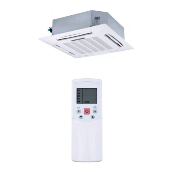
REMOTE CONTROLLERS Wireless Remote Controller Table 21 —Applicable Models for VRF Indoor Units MODEL SERIES ALL INDOOR UNITS Remote Controller 40VM900001 Fig. 35 —Names and Functions (40VM900001) -
Page 24: Address Setting
Address Setting Each indoor unit must have a unique address that can be set from 0-63 for proper system operation. Indoor unit addressing can be done from the remote controller. The entire system (outdoor units, indoor units, and MDC) are included, and should be powered on when setting an address by the remote controllers. -
Page 25: Wired Remote Controller
Wired Remote Controller Table 22 —Applicable Models for VRF Indoor Units MODEL SERIES 40VMF 40VMC 40VMI 40VMW 40VMM 40VMU 40VMH 40VMV 40VML 40VMR 40VMA Remote Controller 40VM900003 (Programmable Controller) Remote Controller (Non-Programmable 40VM900002 Controller) 5. Lef t button/ ROOM TEMP button 1. - Page 26 5. Lef t button 1. MODE button 2. TEMP. UP button 3. ON/OFF button 4. LED 6. MENU/OK button 7. Right button 10. BACK button 9. TEMP. DOWN button 8. FAN button Fig. 38 —Names and Functions—40VM900003 (Programmable Controller) Table 24 —Functional Description BUTTON DESCRIPTION 1.
- Page 27 ADDRESS SETTING Non-Programmable Controller (40VM900002) NOTE: You can only connect one wired controller to an indoor unit. 1. Press ROOM TEMP and SWING together for three seconds. Fig. 39 —Non-Programmable Controller (40VM900002) It displays FE# 00 if there is no address for this IDU. Otherwise, it displays the current address of the indoor unit. 2.
- Page 28 Touch Screen Controller (40VM900005) 1. Touch to select the Service interface. Fig. 41 —Touch Screen Controller (40VM900005) 2. On the “Service” menu, input the password to access the Service setting. The initial password is “0000,” which can be changed. The administrator code cannot be changed, so contact your local distributor if necessary. Fig.
- Page 29 SERVICE MODE Non-Programmable Controller (40VM900002) 1. Press and hold MODE and FAN together for five seconds to enter the interface for parameter settings. Parameter settings are classified into 1G code and 2G code. 1G indicates the parameter category, and 2G indicates parameter content. 2G code 1G code Fig.
- Page 30 Table 26 —1G and 2G Code Descriptions 1G CODE PARAMETER CATEGORY 2G CODE DESCRIPTION Uses room temperature sensor on the IDU Selection room temperature sensor Uses theroom temperature sensor on the 1 (default) wired controller Room temperature sensor temperature 0:-5°F, 1:-4°F, 2:-3°F, 3:-2°F, 4:-1°F, 5:0°F (0 to 10) compensation of wired controller (default), 6:1°F, 7:2°F, 8:3°F, 9:4°F, 10:5°F...
- Page 31 1G CODE PARAMETER CATEGORY 2G CODE DESCRIPTION 0 (default) ΔT = 1°F ΔT = 2°F Setting the opening temperature of dry contact 4; dry contact 4 is opened when the temperature is lower ΔT = 3°F than the set temperature ΔT ΔT = 4°F ΔT = 5°F 0 (default)
- Page 32 Programmable Controller (40VM900003) 1. Press and hold FAN and BACK for five seconds simultaneously to enter the interface for parameter settings. Fig. 47 —Programmable Controller (40VM900003) 2. Press TEMP. UP or TEMP. DOWN to move the cursor and select an entry. 3.
- Page 33 Fig. 49 —Confirm Settings 6. On the parameter settings screen, press BACK once or wait for 30 seconds to automatically exit parameter settings. Fig. 50 —Exit Parameter Settings...
- Page 34 Table 27 —Exit Parameter Screen Description SERVICE MENU DESCRIPTION SET PARAMETER WIRED REMOTE CONTROLLER (Default) Select whether to use the IDU room ROOM TEMP. SENSOR LOCATION temperature sensor or the room temperature sensor of the wired controller. INDOOR UNIT The temperature compensation value for -5°F, -4°F, -3°F, -2°F, -1°F, 0°F (default), 1°F, 2°F, ROOM TEMP.
- Page 35 Touch Screen Wired Controller (40VM900005) 1. Select “Service” menu. 2. Input password to access the service setting menu. The initial password is “0000,” which can be edited. Use the current password if it has been changed. The administrator code cannot be changed, so contact your local distributor if necessary. Fig.
- Page 36 Table 28 —Service Menu List SERVICE MENU DESCRIPTION SET PARAMETER Select whether to use the INDOOR UNIT IDU room temperature ROOM TEMP SENSOR LOCATION sensor or the room temperature sensor of the WIRD REMOTE CONTROL (default) wired controller. The temperature -5ºF, -4ºF, -3ºF, -2ºF, -1ºF, 0ºF (default), 1ºF, 2ºF, 3ºF, ROOM TEMP SENSOR OFFSET compensation value for...
- Page 37 NO. SERVICE MENU DESCRIPTION SET PARAMETER Set occupancy delay OCCUPANCY ON/OFF OFF (default), ON function valid or invalid. Set the time for delayed power-off of the OCCUPANCY unattended IDU (valid only 0 minutes (default),15 minutes, 30 minutes, 60 OCCUPANCY DELAY SENSOR when the IDU is connected minutes...
-
Page 38: Troubleshooting
TROUBLESHOOTING Error Code List CAUTION Turn off power before connecting or disconnecting connector. Table 29 —Error Code List for Indoor Unit ERROR CODE DEFINITION No address when powered on for the first time Heating/Cooling mode conflict error Communication error between indoor unit and outdoor unit Check indoor temperature sensor (T1) Check room temperature sensor (TA) Check evaporator outlet temperature sensor (T2B) -
Page 39: Wiring Diagrams
Wiring Diagrams Fig. 53 —Low Static Duct (40VML Series), Medium Static Duct (40VMM007/009---3), Floor Console Recessed (40VMR) - Page 40 Fig. 54 —Medium Static Duct (40VMM012/015/018/024/030/036/048---3)
- Page 41 Condensate switch Condensate Overflow Fig. 55 —High Static Duct (40VMH Series)
- Page 42 Condensate switch Condensate Overflow Fig. 56 —Outside Air (40VMA036/048/054---3)
- Page 43 Condensate switch Condensate Overflow Fig. 57 —Outside Air (40VMA072/096---3)
- Page 44 Condensate switch Condensate Overflow Fig. 58 —Underceiling/Floor (40VMU Series)
- Page 45 Condensate switch Condensate Overflow Fig. 59 —Compact 4-Way Cassette (40VMC Series)
- Page 46 Fig. 60 —Vertical AHU (40VMV Series)
- Page 47 Fig. 61 —4-Way Cassette (40VMF Series)
- Page 48 Fig. 62 —High Wall (40VMW Series)
- Page 49 BLUE WHITE Blue GRAY YELLOW BLUE WHITE Fig. 63 —1-Way Cassette (40VMI Series)
-
Page 50: Indoor Electric Control Box Details
Indoor Electric Control Box Details LOW PRESSURE DUCT Fig. 64 —Low Pressure Duct (40VML) UNDERCEILING/FLOOR UNIT (40VMU SERIES) Fig. 65 —Underceiling/Floor (40VMU) - Page 51 MEDIUM STATIC DUCT (40VMM SERIES) Fig. 66 —40VMM007, 009---3 Fig. 67 —40VMM015, 018, 024, 030, 036, 048---3...
- Page 52 HIGH STATIC DUCT (40VMH SERIES) Fig. 68 —40VMH024, 030, 036, 048, 054---3 Fig. 69 —40VMH072, 096---3...
- Page 53 OUTSIDE AIR (40VMA SERIES) Fig. 70 —40VMA036, 048, 054---3 Fig. 71 —40VMA072, 096---3...
- Page 54 CASSETTES (40VMF/C SERIES) Fig. 72 —4-Way Cassette (40VMF) Fig. 75 —40VMW005, 024, 030---3 Fig. 73 —Compact 4-Way Cassette (40VMC)
- Page 55 VERTICAL AIR HANDLER (40VMV SERIES) Fig. 74 —Vertical AHU (40VMV) HIGH WALL (40VMW SERIES) Fig. 75 —40VMW005, 007, 009, 012, 015, 018---3...
- Page 56 FLOOR CONSOLE-RECESSED (40VMR SERIES) Fig. 76 —Floor Console (40VMR)
- Page 57 1-WAY CASSETTE (40VMI SERIES) Fig. 77 —1-Way Cassette (40VMI005/007/009/012---3) Fig. 78 —1-Way Cassette (40VMI015/018/024---3)
-
Page 58: Indoor Main Board Instructions
Indoor Main Board Instructions Fig. 79 —Low Pressure and Medium Static Duct (40VML and 40VMM Series) Compact 4-way Cassette (40VMC Series) Floor Console Recessed (40VMR Series) - Page 59 Fig. 80 —4-Way Cassette (40VMF Series)
- Page 60 Fig. 81 —High Wall (40VMW Series)
- Page 61 Fig. 82 —Vertical AHU (40VMV Series)
- Page 62 Fig. 83 —Underceiling/Floor Unit (40VMU) - High Static Duct (40VMH) - Outside Air (40VMA)
- Page 63 Fig. 84 —1-Way Cassette (40VMI)
-
Page 64: Troubleshooting From Indoor Unit
Troubleshooting from Indoor Unit FE: NO ADDRESS WHEN POWERED ON FOR FIRST TIME 1. Error display: IDU display: FE 2. Applicable models: All indoor units 3. Error definition: No address for IDU 4. Possible causes: • IDU set as test mode (Dip switch “SW1_1”) •... - Page 65 DD: HEATING / COOLING MODE CONFLICT 1. Error display: IDU display: dd 2. Applicable models: All indoor units 3. Error definition: • Different operating modes for IDU and ODU (Heat Pump or Single Phase VRF) • Different operating modes for IDUs sharing one port of MDC (Heat Recovery) 4.
- Page 66 E1: COMMUNICATION ERROR BETWEEN IDU AND ODU 1. Error display: IDU display: E1 2. Applicable models: All indoor units 3. Error definition: • Communication error between IDU and ODU (Heat Pump or Single Phase VRF) • Communication error between IDU and MDC (Heat Recovery) 4.
- Page 67 E2~E5: CHECK TEMPERATURE SENSOR 1. Error display: IDU display: E2 (T1 sensor) E3 (TA sensor) E4 (T2B sensor) E5 (T2A sensor) 2. Applicable models: All indoor units 3. Definition: • Temperature sensor (T1, TA, T2A, or T2B) on main board of indoor unit have an open or short circuit. •...
- Page 68 E6: CHECK DC FAN ERROR 1 1. Error display: IDU display: E6 2. Applicable models: 40VMM, 40VML, 40VMW, 40VMF, 40VMC, 40VMU, 40VMR, 40VMI 3. Error definition: DC fan error in IDU -- No fan is detected on the main board, and specific speed difference exists between actual speed and target speed.
- Page 69 E6: CHECK DC FAN ERROR 2 1. Error display: IDU display: E6 2. Applicable models: 40VMV (Vertical AHU) 3. 3. Error definition: DC fan error in IDU -- No fan is detected on the main board 4. Possible causes: • The line from main board to fan motor is loose, disconnected, or improperly connected •...
- Page 70 E6: CHECK DC FAN ERROR 3 1. Error display: IDU display: E6 2. Applicable models: 40VMH, 40VMA (high static pressure and outside air unit) 3. Error definition: DC fan error in IDU -- No fan is detected on the main board, and specific speed difference exists between actual speed and target speed.
-
Page 71: Indoor Unit
E7: EEPROM ERROR (DATA STORAGE) 1. Error display: IDU display: E7 2. Applicable models: All indoor units 3. Error definition: EEPROM error 4. Possible causes: IC7 (Chip) on the main board with a damaged connection E7 error is displayed on the indoor unit Turn off power. - Page 72 E9: COMMUNICATION ERROR BETWEEN IDU AND WIRED REMOTE CONTROLLER 1. Error display: IDU display: E9 2. Applicable models: All indoor units 3. Error definition: Communication error between IDU and wired remote controller normal operation 4. Possible causes: • Abnormal power supply for the wired remote controller (Only 40VM900005) •...
- Page 73 EB: EEV ERROR (SHORT OR STUCK) 1. Error display: IDU display: Eb 2. Applicable models: All indoor units 3. Error definition: EXV is stuck or shorted 4. Possible causes: • Wire that connects to the EEV terminal is loose or broken •...
- Page 74 ED: ODU ERROR 1. Error display: IDU display: Ed 2. Applicable models: All indoor units 3. Error definition: ODU error lasts ten minutes 4. Possible causes: ODU is not in operation Ed error is reported Check the error code of ODU to find out an appropriate solution NOTE: For Heat Recovery systems, check the MDC status because it can cause errors in the ODU.
-
Page 75: Troubleshooting From Remote Controller
Troubleshooting from Remote Controller NO DISPLAY ON WIRED CONTROLLER (PROGRAMMABLE AND NON-PROGRAMMABLE) 1. Error display: No display (the screen does not light on) 2. Applicable models: • Non-programmable controller: 40VM900002 • Programmable controller: 40VM900003 3. Error definition: No display on wired controller Check wiring between IDU and controller 4. - Page 76 NO DISPLAY ON WIRED CONTROLLER (TOUCH SCREEN CONTROLLER) 1. Error display: No display (the screen does not light) 2. Applicable models: Touch screen controller: 40VM900005 3. Error definition: No display on wired controller Check the power supply of wired controller 4.
- Page 77 E9: COMMUNICATION ERROR BETWEEN IDU AND CONTROLLER 1. Error display: Display on wired controller: E9 2. Applicable models: • Non-programmable controller: 40VM900002 • Programmable controller: 40VM900003 • Touch screen controller: 40VM900005 3. Error definition: • Communication error between the wired controller and IDU •...
- Page 78 F7: EEPROM ERROR ON WIRED REMOTE CONTROLLER 1. Error display: Display on wired remote controller: F7 2. Applicable models: • Non-programmable controller: 40VM900002 • Programmable controller: 40VM900003 3. Error definition: EEPROM error on wired controller Reset the wired controller 4. Possible causes: •...
-
Page 79: Appendix
APPENDIX Table 31 —Resistance of Temperature Sensor A* TEMP. (°F) RESISTANCE (KΩ) VOLTAGE (V) TEMP. (°F) RESISTANCE (KΩ) VOLTAGE (V) TEMP. (°F) RESISTANCE (KΩ) VOLTAGE (V) -38.2 387.13 0.10 51.8 19.62 1.46 141.8 2.27 3.90 -36.4 360.98 0.11 53.6 18.66 1.51 143.6 2.19... - Page 80 © Carrier Corporation 2019 Manufacturer reserves the right to discontinue, or change at any time, specifications or designs without notice and without incurring obligations. Catalog No. 19-40VM001-06 Printed in U.S.A. Form 40VM-1SM Pg 80 8-19 Replaces: New...
Need help?
Do you have a question about the 40VM Series and is the answer not in the manual?
Questions and answers