Table of Contents
Advertisement
Installation and Maintenance Instructions
CONTENTS
SAFETY CONSIDERATIONS . . . . . . . . . . . . . . . . . . . 1
GENERAL . . . . . . . . . . . . . . . . . . . . . . . . . . . . . . . . . . . 2
DIMENSIONS . . . . . . . . . . . . . . . . . . . . . . . . . . . . . . 4
FAN CURVE CHARACTERISTICS. . . . . . . . . . . . . . . 6
INSTALLATION . . . . . . . . . . . . . . . . . . . . . . . . . . . . . . . 8
Step 1 - Unpack and Inspect Units . . . . . . . . . . . . 8
Step 3 - Mount the Units. . . . . . . . . . . . . . . . . . . . . . 9
Step 4 - Connect Piping . . . . . . . . . . . . . . . . . . . . . 10
Step 6 - Installing the LED Display Panel . . . . . 14
Step 7 - Position and Connect Controller . . . . . 14
ACB INTERFACE . . . . . . . . . . . . . . . . . . . . . . . . . . 18
START-UP . . . . . . . . . . . . . . . . . . . . . . . . . . . . . . . . 18
MAINTENANCE . . . . . . . . . . . . . . . . . . . . . . . . . . . 18
Fan Assembly Maintenance . . . . . . . . . . . . . . . . . 18
TROUBLESHOOTING . . . . . . . . . . . . . . . . . . . . . . . . . 23
APPENDIX A - DIP SWITCH SETTINGS . . . . . . . . . . 25
SAFETY CONSIDERATIONS
Improper
installation,
adjustment,
maintenance, or use can cause explosion, fire, electrical shock,
or other conditions that may cause death, personal injury, or
property damage. The qualified installer or agency must use
factory-authorized kits or accessories when modifying this
product.
Follow all safety codes. Wear safety glasses, protective
clothing, and work gloves. Use quenching cloth for brazing
operations. Have fire extinguisher available. Read these
instructions thoroughly and follow all warnings or cautions
included in literature and attached to the unit. Consult local
building codes and the current editions of the National
Electrical Code (NEC) ANSI/NFPA (American National
Standards Institute/National Fire Protection Association) 70. In
Canada, refer to the current editions of the Canadian Electrical
Code CSA (Canadian Standards Association) C22.1.
Understand the signal words -
.
identifies the most serious hazards,
CAUTION
DANGER
which will result in severe personal injury or death.
signifies hazards that could result in personal injury
WARNING
or death.
is used to identify unsafe practices, which
CAUTION
would result in minor personal injury or product and property
damage.
Recognize safety information. This is the safety-alert
symbol ( ). When this symbol is displayed on the unit and in
Manufacturer reserves the right to discontinue, or change at any time, specifications or designs without notice and without incurring obligations.
Catalog No.20-40VMA001-01
Page
. . . . . . . . . . . . . . . . . . . . . 9
alteration,
service,
,
, and
DANGER
WARNING
Printed in U.S.A.
Form 40VMA-2SI
Variable Refrigerant Flow (VRF) Systems
instructions or manuals, be alert to the potential for personal
injury.
Electrical shock can cause personal injury and death. Shut
off all power to this equipment during installation. There
may be more than one disconnect switch. Tag all
disconnect locations to alert others not to restore power
until the work is completed.
DO NOT re-use compressor oil or any oil that has been
exposed to the atmosphere. Dispose of oil per local codes
and regulations. DO NOT leave the refrigerant system open
to air any longer than the actual time required to service the
equipment. Seal circuits being serviced and charge with dry
nitrogen to prevent oil contamination when timely repairs
cannot be completed.
Failure to follow these procedures may result in damage to
equipment. For information about replacement oil type and
viscosity, see the Installation, Start-Up, and Service
Instructions for the 38VMAH and 38VMAR outdoor units.
DO NOT USE TORCH to remove any component. System
contains oil and refrigerant under pressure.
To remove a component, wear protective gloves and
goggles and proceed as follows:
A. Shut off electrical power to unit.
B. Recover refrigerant to relieve all pressure from
system using both the high-pressure and low
pressure ports.
C. Traces of vapor should be displaced with nitrogen
and the work area should be well ventilated.
Refrigerant in contact with an open flame produces
toxic gases.
D. Cut the component connection tubing with a tubing
cutter and remove the component from unit. Use a
pan to catch any oil that may come out of the lines
and as a gage for how much oil to add to the system.
E. Carefully unsweat remaining tubing stubs when
necessary. Oil can ignite when exposed to torch
flame.
Failure to follow procedures may result in personal injury
or even death.
When installing the equipment in a small space, provide
adequate measures to avoid refrigerant concentration
exceeding safety limits due to refrigerant leak.
In case of refrigerant leak during installation, ventilate the
space immediately. Failure to follow this procedure may
lead to personal injury.
Pg 1
40VMA036-096
Outside Air Unit for
WARNING
WARNING
WARNING
WARNING
2-20
Replaces: 40VMA-1SI
Advertisement
Table of Contents

Related Manuals for Carrier 40VMA Series


Summary of Contents for Carrier 40VMA Series
-
Page 1: Table Of Contents
40VMA036-096 Outside Air Unit for Variable Refrigerant Flow (VRF) Systems Installation and Maintenance Instructions CONTENTS instructions or manuals, be alert to the potential for personal injury. Page SAFETY CONSIDERATIONS ....1 WARNING GENERAL . -
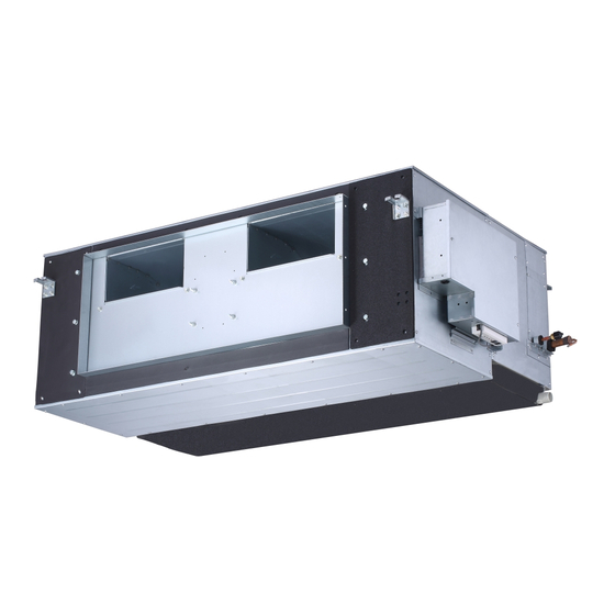
Page 2: General
GENERAL The 40VMA outside air fan coil unit offers simple operation This manual should be fully reviewed in advance before initial and long service with proper installation, operation, and regular installation, start-up, and any maintenance. Contact your local maintenance. The equipment is initially protected under the sales representative or the factory with any questions BEFORE manufacturer’s standard warranty;... - Page 3 Table 2 —40VMA Physical Data UNIT 40VMA POWER SUPPLY (V-Ph-Hz) 208/230-1-60 36,000 48,000 53,500 72,000 96,000 COOLING CAPACITY (Btuh) 24,000 30,000 36,000 47,000 59,000 HEATING CAPACITY (Btuh) INDOOR FAN MOTOR Type 60*2 80*2 Input (W) INDOOR COIL Number of Rows Fin Spacing (fins/in.) Hydrophilic Aluminum Fin Type...
-
Page 4: Dimensions
DIMENSIONS Fig. 2 —40VMA036-054 Dimensions NOTE: All dimensions are shown in inches. - Page 5 DIMENSIONS (CONT.) Fig. 3 —40VMA072-096 Dimensions NOTE: All dimensions are shown in inches.
-
Page 6: Fan Curve Characteristics
FAN CURVE CHARACTERISTICS 40VMA048---3 40VMA036---3 0.88 0.88 0.72 0.72 0.64 0.64 0.56 0.56 0.48 0.48 0.32 0.32 0.24 0.24 0.16 0.16 0.08 0.08 Air ow Air ow Fig. 4 —Size 036 Fig. 5 —Size 048 Range of Available Airflow Rate in H-Speed Range of Available Airflow Rate in H-Speed Max Point Rating Point... - Page 7 FAN CURVE CHARACTERISTICS (CONT.) 40VMA072---3 40VMA054---3 1.12 0.88 1.04 0.96 0.72 0.88 0.64 0.72 0.56 0.64 0.48 0.56 0.48 0.32 0.32 0.24 0.24 0.16 0.16 0.08 0.08 400 450 500 550 600 650 700 750 800 850 900 950 1000 1100 1200 1300...
-
Page 8: Installation
FAN CURVE CHARACTERISTICS (CONT.) NOTES: (For Fig. 4 - 8): 1. There are multiple ESP settings for each ducted unit. 40VMA096---3 2. All fan curves show examples of fan characteristics of the MAX. ESP, RATING ESP, and MIN. ESP settings. These 1.12 curves are shown for High (H), Medium (M), and Low (S) 1.04... -
Page 9: Step 2 - Position The Unit
PREPARING JOB SITE FOR UNIT INSTALLATION — To save time and to reduce the possibility of costly errors, set up a complete sample installation in a typical room at the job site. Check all critical dimensions such as pipe, wire, and duct connections requirements. -
Page 10: Step 4 - Connect Piping
Step 4 — Connect Piping — • When multiple units are connected to a common condensate drain, ensure that the drain is large enough to CONDENSATE PIPING — The unit is supplied with a one- accommodate the volume of condensate from all units. It inch OD drain connection to connect copper or PVC drain is also recommended to have an air vent in the piping as shown in Fig. -
Page 11: Step 5 - Complete The Electrical Connections
REFRIGERANT PIPING CAUTION WARNING When connecting from an indoor unit to an outdoor unit, All units must be wired strictly in accordance with the the isolation valve at the outdoor unit should be in the wiring diagram furnished with the unit. Any wiring closed position throughout the refrigerant piping process. - Page 12 To outdoor/indoor/MDC units comm. bus ACB interface CN50 WHITE To wired controller CN13 ON/OFF BLUE comm. bus SWITCH CN51 CN51 FAN CTON HTON AUXH ( Current range: 0-1A) Occupancy sensor/ON-OFF ( Voltage range: 0-24V AC/DC) (Dry contact) “ +5V GND +12V ” ONLY USED FOR TESTING Display board...
- Page 13 To outdoor/indoor/MDC units comm. bus ACB interface CN50 BLUE CN13 CN13 BLACK WHITE To wired controller ON/OFF comm. bus SWITCH BLUE CN51 CN51 BLUE FAN CTON HTON AUXH ( Current range: 0-1A) Occupancy sensor/ON-OFF ( Voltage range: 0-24V AC/DC) (Dry contact) “...
-
Page 14: Step 6 - Installing The Led Display Panel
Step 6 — Installing the LED Display Panel — 1. Insert the buckles into the grooves in the electronic control box, and slide the display panel horizontally to lock in place as shown in Figs. 18 and 19. Fig. 20 —LED Display Panel Installed Fig. - Page 15 1. Cut the connector on the outdoor unit side as shown in Fig. 22. Fig. 25 —Connecting the Communication Wires If it is not possible to buy communication wires from Carrier, connect the indoor unit side of the communication wires using the connector provided with the accessories as shown in Fig.
- Page 16 outdoor unit Centralized controller wired controller Indoor unit 1# Indoor unit 2# Main MDC unit Indoor unit 3# Indoor unit 4# wired controller MDC unit Indoor unit 5# Maximum wiring length L1+L2 < 3937 ft 18AWG, 2-Core Stranded Shield L3 < 3937 ft 18AWG, 2-Core Stranded Shield L4 <...
- Page 17 wired controller z i l l l o Indoor unit 1# Indoor unit 2# Indoor unit 3# Indoor unit 4# • • • • wired controller Indoor unit 5# Matched resistance (network matchded Indoor unit 6# wire group) Maximun wiring length Fig.
-
Page 18: Acb Interface
IMPORTANT: The system can connect 64 indoor units with System Operation Check — Once the installation and pre-start different system addresses. If two indoor units in the same checks are completed, follow these steps: system have identical addresses, abnormal operation will 1. - Page 19 40VMA036-054 Fig. 30 —Fan Disassembly 036-054 Fig. 31 —Fan Disassembly 036-054 Fig. 30 provides an example of the unit. 1. Remove the 12 screws from the fixed Safety Drain Tray, and take off the tray as shown in Fig. 31. 2.
- Page 20 Fig. 32 —Fan Disassembly 036-054 Fig. 33 —Fan Disassembly 036-054 1. Remove all 12 screws from the Safety Drain Tray, and remove the safety drain tray as shown in Fig. 32. 2. Remove all four bolts from the fan assembly as shown in Fig. 33. 3.
- Page 21 40VMA072 - 096 Fig. 34 —Fan disassembly (072-096) 1. Remove the bottom cover plate as shown in Fig. 34. 2. Remove the six bolts from the front plate. 3. Support the fan sub-assembly from the bottom, and lift up to remove the fan sub-assembly. 4.
- Page 22 Wireless Remote Controller (40VM900001) Programmable Controller (40VM900003) Indoor unit addressing can be performed using the wireless When setting an address, connect only one wired controller to remote controller. When using the wireless controller, the user an indoor unit. must maintain a line of sight with the receiver on the indoor Press FAN and BACK simultaneously for five seconds to unit.
-
Page 23: Troubleshooting
TROUBLESHOOTING Figure 38 shows the indoor unit’s LED display panel. See Table 5 for a summary of display indicators. Table 6 lists problems, possible causes, and possible solutions. Fig. 38 —LED Display Panel Table 5 —LED Display Indicators LED DISPLAY MODE/STATUS ERROR CODE Operation Light ON... - Page 24 Table 6 —Troubleshooting DESCRIPTION POSSIBLE CAUSES POSSIBLE SOLUTIONS ERROR System is in cooling or fan only mode and All units should be in cooling mode for Heating / Cooling Mode Conflict heating signal is received from a unit on the system to stay in cooling mode.
-
Page 25: Appendix A - Dip Switch Settings
Fig. B —SW8 Settings Fig. A — SW1 Settings © Carrier Corporation 2020 Manufacturer reserves the right to discontinue, or change at any time, specifications or designs without notice and without incurring obligations. Catalog No.20-40VMA001-01 Printed in U.S.A.
Need help?
Do you have a question about the 40VMA Series and is the answer not in the manual?
Questions and answers