Carrier 40VMF Installation And Maintenance Instructions Manual
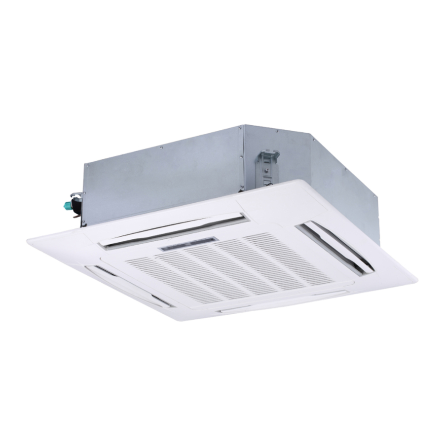
4-way cassette indoor unit for variable refrigerant flow (vrf) systems
Hide thumbs
Also See for 40VMF:
- Installation and operating instructions (2 pages) ,
- Installation and operating instructions manual (12 pages)
Table of Contents
Advertisement
Installation and Maintenance Instructions
TABLE OF CONTENTS
SAFETY CONSIDERATIONS . . . . . . . . . . . . . . . . . . . 1
GENERAL . . . . . . . . . . . . . . . . . . . . . . . . . . . . . . . . . . . 2
INSTALLATION . . . . . . . . . . . . . . . . . . . . . . . . . . . . . . . 6
Step 1 - Unpack and Inspect Units . . . . . . . . . . . . 6
Step 2 - Position the Unit . . . . . . . . . . . . . . . . . . . 6
Step 3 - Mount the Unit . . . . . . . . . . . . . . . . . . . . . 7
Step 4 - Connect Piping . . . . . . . . . . . . . . . . . . . . . 8
Step 5 - Complete Electrical Connections . . . . . . 9
Step 6 - Position and Connect Controller. . . . . . 11
ACB Interface . . . . . . . . . . . . . . . . . . . . . . . . . . . 14
START-UP . . . . . . . . . . . . . . . . . . . . . . . . . . . . . . . . . . 14
Pre-Start Check . . . . . . . . . . . . . . . . . . . . . . . . . . . 14
System Operation Check . . . . . . . . . . . . . . . . . . . 14
MAINTENANCE. . . . . . . . . . . . . . . . . . . . . . . . . . . . . . 14
INDOOR UNIT ADDRESSING. . . . . . . . . . . . . . . . . 14
Wireless Remote Controller (40VM900001) . . . . 14
Non-Programmable Controller. . . . . . . . . . . . . . . 15
Programmable Controller . . . . . . . . . . . . . . . . . . 15
TROUBLESHOOTING . . . . . . . . . . . . . . . . . . . . . . . . 17
Replacement Parts . . . . . . . . . . . . . . . . . . . . . . . . 18
APPENDIX A - DIP SWITCH SETTINGS . . . . . . . . 19
SAFETY CONSIDERATIONS
Improper
installation,
maintenance, or use can cause explosion, fire, electrical shock,
or other conditions, which may cause death, personal injury, or
property damage. The qualified installer or agency must use
factory-authorized kits or accessories when modifying this
product.
Follow all safety codes. Wear safety glasses, protective
clothing, and work gloves. Use quenching cloth for brazing
operations. Have fire extinguisher available. Read these
instructions thoroughly, and follow all warnings or cautions
included in literature and attached to the unit. Consult local
building codes and the current editions of the National
Electrical Code (NEC) ANSI/NFPA (American National
Standards Institute/National Fire Protection Association) 70. In
Canada, refer to the current editions of the Canadian Electrical
Code CSA (Canadian Standards Association) C22.1.
Understand the signal words -
.
identifies the most serious hazards,
CAUTION
DANGER
which will result in severe personal injury or death.
signifies hazards that could result in personal injury
WARNING
or death.
is used to identify unsafe practices, which
CAUTION
would result in minor personal injury or product and property
damage.
Manufacturer reserves the right to discontinue, or change at any time, specifications or designs without notice and without incurring obligations.
Catalog No. 20-40VMF002-01
adjustment,
alteration,
,
DANGER
WARNING
Printed in U.S.A.
4-Way Cassette Indoor Unit for
Variable Refrigerant Flow (VRF) Systems
Recognize safety information. This is the safety-alert
symbol (
Page
instructions or manuals, be alert to the potential for personal
injury. Installing, starting up, and servicing equipment can be
hazardous due to system pressure, electrical components, and
equipment location.
Electrical shock can cause personal injury and death. Shut
off all power to this equipment during installation. There
may be more than one disconnect switch. Tag all
disconnect locations to alert others not to restore power
until work is completed.
When installing the equipment in a small space, provide
adequate measures to avoid refrigerant concentration
exceeding safety limits due to refrigerant leak. In case of
refrigerant leak during installation, ventilate the space
immediately. Failure to follow this procedure may lead to
personal injury.
service,
DO NOT USE TORCH to remove any component. System
contains oil and refrigerant under pressure.
To remove a component, wear protective gloves and
goggles and proceed as follows:
a. Shut off electrical power to unit.
b. Recover refrigerant to relieve all pressure from
system using both high-pressure and low pressure
ports.
c. Traces of vapor should be displaced with nitrogen
and the work area should be well ventilated.
Refrigerant in contact with an open flame produces
toxic gases.
d. Cut component connection tubing with tubing cutter
and remove component from unit. Use a pan to catch
any oil that may come out of the lines and as a gage
for how much oil to add to the system.
, and
e. Carefully unsweat remaining tubing stubs when
necessary. Oil can ignite when exposed to torch
flame.
Failure to follow these procedures may result in personal
injury or death.
Form 40VMF-4SI
40VMF009A-048A
). When this symbol is displayed on the unit and in
WARNING
WARNING
WARNING
Pg 1
07-20
Replaces: 40VMF-3SI
Advertisement
Table of Contents

Related Manuals for Carrier 40VMF


Summary of Contents for Carrier 40VMF
-
Page 1: Table Of Contents
Manufacturer reserves the right to discontinue, or change at any time, specifications or designs without notice and without incurring obligations. Catalog No. 20-40VMF002-01 Printed in U.S.A. Form 40VMF-4SI Pg 1 07-20 Replaces: 40VMF-3SI... -
Page 2: General
GENERAL CAUTION The 40VMF 4-way ceiling cassette effectively makes each area served an independently controlled temperature zone. Through DO NOT re-use compressor oil or any oil that has been thermostatic control of operations, conditions can be varied to exposed to the atmosphere. Dispose of oil per local codes suit diverse requirements and activities. - Page 3 Table 1 — 40VMF Physical Data UNIT 40VMF 009A 012A 015A 018A 024A 030A 036A 048A POWER SUPPLY (V-Ph-Hz) 208/230-1-60 TOTAL COOLING CAPACITY (Btuh) 9,000 12,000 15,000 18,000 24,000 30,000 36,000 48,000 SENSIBLE COOLING CAPACITY (Btuh) 8,620 10,880 13,370 18,220...
- Page 4 Table 2 — Components Shipped With Unit NAME SHAPE QUANTITY FUNCTION To connect the construction cover board to the fan motor Washer To connect the construction cover board to the fan motor Construction cover board Used to cover the fan motor Bolt To connect the construction cover board to the fan motor Insulation...
- Page 5 37-3/8 4-1/8 30-3/4 33-1/8 5-3/4 1-3/4 34-5/8 (Ceiling hole) 40VMF UNIT SIZE DIMENSION A 009A 012A 015A 018A 024A 030A 036A 048A NOTE: All dimensions shown in inches. Fig. 2 —40VMF009A-048A Dimensions...
-
Page 6: Installation
Failure of any unit caused by deposits of foreign material on DIMENSION (in.) 40VMF UNIT SIZE motor or blower wheels will not be covered by manufacturer’s warranty. Some units and/or job conditions may require some 009-015 form of temporary covering during construction. -
Page 7: Step 3 - Mount The Unit
Fig. 7 —Mounting Hole Locations any dust and debris from settling inside the unit. Use the M6 bolt, washer and nut as shown in Fig. 5 below. Table 3 — Unit Weight 40VMF UNIT WEIGHT (lb)* Unit body Central hole 009A 71.0... -
Page 8: Step 4 - Connect Piping
Hook Panel hook Piping joint Drainage pipe joint a40-1722 Louver Fig. 8 —Threaded Rod motor Hook bolt INSTALLING PANEL NOTE: Panel is ordered separately. Phillips 1. Remove the grille from the panel by sliding the grille screwdriver latches toward the center of the panel. Louver motor 2. -
Page 9: Step 5 - Complete Electrical Connections
7-7/8” 7-7/8” 7-7/8” 2“~4” 2“~4” 2“~4” Connection assembly of water outlet Main drainage pipe Gradient: 1/50~1/100 Fig. 13 —Using a Main Drain to Serve Multiple Indoor Units with Internal Condensate Pumps • Condensate piping should slope downward in the • Before insulating the suction and liquid refrigeration direction of condensate flow with a minimum gradient of pipes, perform pressure and leak tests. - Page 10 Table 5 — 40VMF Electrical Data Once the pipe work is complete, the electrical supply can be connected by routing the cable through the appropriate casing POWER SUPPLY holes or knockouts and connecting the supply and ground 40VMF UNIT SIZE cables to the unit’s power terminal.
-
Page 11: Step 6 - Position And Connect Controller
4. Communication wire must not form a closed loop. Fig. 19 —Connecting the Communication Wires If it is not possible to buy communication wires from Carrier, connect the indoor unit side of communication wires using the connector provided with the accessories as shown in Fig. 20. - Page 12 Touch screen wired controller outdoor unit Centralized controller NOTE: 24 v. DC Power (Field Supplied) HA HB Indoor unit 1# To No.1 indoor To No.2 indoor Indoor unit 2# Main MDC unit To outdoor To No.3 indoor To No.4 indoor To Sub MDC Indoor unit 3# Indoor unit 4#...
- Page 13 Touch screen wired controller outdoor unit Centralized controller NOTE: 24 v. DC Power (Field Supplied) HA HB Indoor unit 1# Indoor unit 2# Indoor unit 3# Indoor unit 4# wired controller NOTE: Power from IDU HA HB Indoor unit 5# Network Resistor Indoor unit 6# MAXIMUM WIRING LENGTH...
-
Page 14: Acb Interface
ACB Interface — 3. While the system is in operation, check the following on The ACB interface is a dry contact the outdoor unit: board that can output up to four signals controlling devices. Refer to Fig. 23 for connecting devices to ACB interface board. a. -
Page 15: Non-Programmable Controller
Click TEMP. UP or TEMP. DOWN to change 00 to the de- sired address as shown in Fig. 26. Press OK to confirm and exit the setting interface. AUTO TEMP COOL 1 – MODE SETTING 2 – FAN SPEED SETTING CLOCK HEAT HOUR... - Page 16 3. Press TEMP. UP or TEMP. DOWN to choose the address you want to set. See Fig. 28. Press MENU/OK to send this address to the IDU. MODE TEMP. UP ON/OFF MENU TEMP. DOWN BACK Fig. 28 —Programmable Controller Setting IDU Address 4.
-
Page 17: Troubleshooting
TROUBLESHOOTING Fig. 29 shows the LED display panel on the indoor unit. See Table 6 for a summary of display indicators. Table 7 lists problems, possible causes, and possible solutions. A40-1716 OPERATION TIMER DEF./FAN ALARM a40-1842 Fig. 29 —LED Display Panel Table 6 —... -
Page 18: Replacement Parts
MINIMUM CIRCUIT AMPACITY 0.73 A MAX FUSE OR HACR BREAKER 15 A 0.59 A FAN MOTOR OUTPUT 80W (1/8HP) REFRIGERANT R410A HIGH 580 PSIG DESIGN PRESSURE 320 PSIG SERIAL NO. 1616V000 01 Carrier Corporation Fig. 30 — Unit Serial Plate (Example) -
Page 19: Appendix A - Dip Switch Settings
APPENDIX A — DIP SWITCH SETTINGS There are 2 DIP switches on the main board. Figures A and B show the settings for each parameter controlled by a switch. Switches are shown in the default settings. — Thermal off fan off —... - Page 21 © Carrier Corporation 2020 Manufacturer reserves the right to discontinue, or change at any time, specifications or designs without notice and without incurring obligations. Catalog No. 20-40VMF002-01 Printed in U.S.A. Form 40VMF-4SI Pg 21 07-20 Replaces: 40VMF-3SI...
Need help?
Do you have a question about the 40VMF and is the answer not in the manual?
Questions and answers