
Related Manuals for Pulsar PSBD 5012


Summary of Contents for Pulsar PSBD 5012
- Page 1 PSU-B-13,8V/S-5A/1/EL-TR-40Ah/MC PSBD 5012 v.1.1 Buffer, switching power supply unit. Edition: 2 from the 21 June.2010 Supercedes edition: 1 from the 21 April.2009...
-
Page 2: Table Of Contents
Metal casing IP20 with a space for 17Ah/12V battery. 12V DC buffer (switching) power-supply unit, with the total PSBD 5012 current capacity 5A and output voltage 11,0V-13,8V. Equipped PSU-B-13,8V/S-5A/1/EL-TR-40Ah/MC with the AC supply absence indication system (battery assisted operation), failure and casing sabotage indication system. -
Page 3: Block Diagram
Information about additional equipment for PSBC5012 power-supply (options of maximal configuration): - 2 x converter DC/DC 2.5A/5V (ADC 255) + 2 x LB5/AW fuse block (AWZ 536) + 40Ah - 2 x voltage reducer RN-2.5A/12V (RN250) + 2 x LB5/AW fuse block (AWZ 536) + 40Ah - 1 x voltage reducer RN-5.0A/12V (RN500) + 2 x LB5/AW fuse block (AWZ 536) + 40Ah 1.2. - Page 4 1.3. Description of elements and connection links of the power-supply unit (tab.1, tab.2, fig.2). Table 1. Element no. Description [Fig. 2] F1 fuse in the battery circuit START pushbutton (power activation without AC supply) JP-B, dip switch - configuration of UVP battery protection function JP-B = protection function (disconnection) of the battery off •...
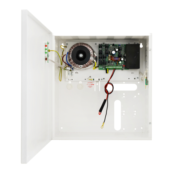
- Page 5 Fig.2. The view of the power-supply.
-
Page 6: Technical Parameters
1.4. Technical parameters: - electrical parameters (tab.3) - mechanical parameters (tab.4) - operation safety (tab.5) - operation parameters (tab.6) Electrical parameters (tab. 3). Supply voltage 230V/AC (-15%/+10%) Supply frequency 50Hz PSU power P 69 W Current consumption 0.61 A max. (7.0 A „cold boot”) Output voltage 11.0 V÷13.8 V DC –... -
Page 7: Installation
Operation safety (tab.5). Protection class PN-EN 60950-1:2004 I (first) Protection grade PN-EN 60529: 2002 (U) IP20 Electrical strength of insulation: - between input (network) circuit and output circuits of power-supply (I/P-O/P) 3000 V/AC min. - between input circuit and PE protection circuit (I/P-FG) 1500 V/AC min. -
Page 8: The Power Supply Operation Indication
7. Using the dip switch ‘JP-B’ determine whether the function of disconnecting the discharged battery U<10V (+/- 5%) is to be on or off. The battery protection is on if the dip switch ‘JP-B’ is removed. 8. Activate the ~230V/AC supply (the AC red diode should be permanently illuminated, and AUX diode should be permanently illuminated). -
Page 9: Battery Assisted Operation
4.2 Battery assisted operation. In the case of power failure, in the unit will instantly switch to the battery assisted operation. In order to activate the operation of the PSU from the battery itself, connect the BAT connectors in accordance with the indications: +BAT red to ‘plus’ and, -BAT black to 'minus’ of the battery and press and keep depressed for five seconds the START pushbutton on the equipment board. - Page 10 GENERAL WARRANTY CONDITIONS 1. Pulsar K. Bogusz Sp.j. (manufacturer) grants a two-year quality warranty for the equipment, starting from the date of purchase placed on the purchase order.
Need help?
Do you have a question about the PSBD 5012 and is the answer not in the manual?
Questions and answers