Advertisement
Quick Links
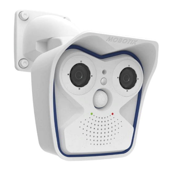
Sensor Module Combinations
Mx-M16A/B*
2 optical
Day/Night/LPF
Day/Night/LPF
*Variant Mx-M16B supports MOBOTIX MxBus modules
Standard Delivery M16
M.11
M.10
M.9
M.8
M.7
M.6
M.5
M.4
M.3
M.2
M.1
1.19
1.20
1.18
Standard Delivery
Item
Count
Part Name
Camera housing with mainboard and wall mount (installed),
1.1
1
without sensor modules and front element
1.2
1
Front element with additional sensors (installed)
1.3
2
Transport plugs (installed)
Blind module (must be installed when using only one sensor
1.4
1
module)
1.5
4
Inner housing cover (installed)
Stainless steel Allen screw with flat head M4x8 for inner housing
1.6
4
cover (installed)
Sensor Modules of the M16 (to Be Ordered Separately, Thermal Sensor Pre-Installed)
Sensor module
SMA-S-6D/N/L016
Dome
Plastic nut
Connections and Initial Operation of the M16
You can find detailed information on the installation and connections of the M16 in the M15 Camera Manual (PDF, available on www.mobotix.com >
Support > Download Center > Documentation > Manuals).
Please note that the position of the SD card holder has changed (see figure below, at the right), the boot options of this camera have changed compared
to its predecessor (see «Boot Options of the M16» on page 2) and the camera only has one key ("L").
Regarding the rest of the initial operation of the M16, please see the M15 Camera Manual in Chapter 3, «Initial Operation». The first access follows the
procedure described in the same manual in the section «Initial Operation of the Camera». All other tasks require access to the camera's user interface in
the browser. Enter the camera's IP address into the address bar of the browser (user "admin", password "meinsm"; password must be changed upon first
login – camera software V5.1.x and higher).
Camera housing
Preparing the M16 for Installation
To facilitate the installation of the camera, you should complete the following tasks before actually installing the camera.
1. CAUTION!
• Only exchange sensor modules when powered off!
• When operating the camera with only one sensor module, always
install the supplied blind module. No operation with transport plugs!
• Thermal sensor modules are always pre-installed and cannot be removed!
2. Installing the Sensor Modules
Remove the plastic nut from the sensor module
plugs
.
2
Push the sensor module cable plug into the connector at the back of the
module housing
. Secure the plug using the blue bayonet catch as
3
shown
.
4
Insert the sensor module. Make sure that the MOBOTIX lettering on the
sensor module is at the "9 o'clock" position as shown in the figure
Place the back of the black module wrench onto the two holes of the
sensor module
.
6
Using the black module wrench, turn the sensor module clockwise until
it stops
. If desired, insert the two security clips
7
housing as described in «Opening/Closing the Camera Housing».
Opening/Closing the Camera Housing
The following tasks require opening the camera housing and removing the front element of the M16 in order to get to the interior of the camera:
Inserting the security clips, exchanging the Ethernet patch cable, connecting the MxBus two-wire line, connecting the USB cable, exchanging the MicroSD
card (see also «Inserting/Exchanging the SD Card» on page 2).
CAUTION: Make sure the power supply to the camera is disconnected before opening the housing!
1. Opening the Camera Housing
Place the camera face-down on a clean and dry surface. Remove the two
rubber plugs at the back of the camera housing. Using the supplied 5 mm
Allen wrench, loosen the two bolts at the back of the camera housing.
Leave the bolts and washers in the camera housing.
Using the Allen wrench,
cautiously
fashion
onto the left and the right bolt
out of the front of the housing.
Tilt the front element forward as shown in the figure
2. Inserting the Security Clips
To protect the modules against unwanted removal, insert the two red
security clips at the insides of the sensor modules at the proper location
(
inserted,
locked). Make sure that the security clips are properly
1
2
locked in their seatings
.
3
3. Closing the Camera Housing
Before inserting the front element, make sure that the sensor module cables
of both image sensors are running at the inside of the screw bore
Place the camera on its right side (as seen by the camera) as shown and
insert the front element. When pushing the front element into the housing
(
, red arrows), take care not to crush any cables.
2
When inserting and closing the front element, take special care to guide
the cable of the left sensor module under the rubber hook
Press the front element into the camera housing by evenly applying pres-
sure
. Tighten the screws with washers.
4
Finally, apply the rubber plugs at the back of the housing that you removed
earlier.
Mx-M16A/B*
Mx-M16A/B*
1 optical
1 Thermal/Thermal-TR,
1 optical Day/Night/LPF
1.1
1.4
1.6
1.8
1.12
1.14
1.15
1.17
1.13
1.16
Sensor module
SMA-S-6D/N/L036–237
Protective
glass insert
Plastic nut
Wall Mount
Sensor mod-
ules
PIR sensor
LEDs
Front element
Key L
Ethernet patch cable
. Remove the transport
1
. Open the camera
8
push from behind
in an alternating
and push the front element
1
.
2
3
M16 AllroundDual
Quick Install
Standard Delivery
Item
Count
1.7
1.2
1.8
1.9
1.3
1.10
1.11
1.12
1.5
1.13
1.14
1.7
1.15
1.16
1.9
1.17
1.18
1.10
1.19
1.20
1.11
Mounting Supplies
Item
Count
M.1
M.2
M.3
M.4
M.5
M.6
M.7
M.8
M.9
M.10
M.11
Sensor module
SMA-S-6D/N/L500
Lens cover
MxBus
USB
Sensor mod-
ules
I/O cable to front
element (red clips)
Front element
M16 with two transport
plugs:
No operation allowed!
3
.
5
.
1
3
!
Part Name
Cable lock black with bayonet catch (Ethernet patch cable, USB,
2
one installed, one supplied)
2
Single wire plug, blue (MxBus, USB, installed)
1
MicroSD card (SDXC, SDHC pre-installed)
1
Ethernet patch cable, 50 cm/19.7 in with sealing (installed)
2
Sensor module cable 15 cm/6 in (installed in camera)
1
I/O cable with red clips to front element 15 cm/6 in (installed)
1
Hinged ferrite for Ethernet cable (installed)
1
Hinged ferrite for sensor module cable (installed)
2
Rubber plug for covering mounting screws, white
3
Stainless steel Allen screw M6x30 (installed)
3
Stainless steel washer dia. 6.4 mm (installed)
Stainless steel spring washer dia. 6.4 mm (wall/ceiling mount,
1
installed)
1
Stainless steel lock nut M6 (wall/ceiling mount, installed)
1
Rubber plug, black (installed)
Part Name
4
Stainless steel washer dia. 6.4 mm
4
Dowels 8 mm
4
Stainless steel wood screw with hex head 6x50 mm
1
Allen wrench 2.5 mm
1
Allen wrench 5 mm
1
Lens wrench (SMA-S-6D/N/L016 lens, glass/filter insert, dome)
1
Module key (sensor module, focusing of lenses)
1
Rubber sealing for wall/ceiling mount, white
1
Ceiling mount for VarioFlex mount
4
Protection cover for screw, white
4
Security clip for sensor or blind modules, red
(all except Thermal)
Sensor module cable
Top (markings)
Sensor module R
USB
Ethernet
Slot for MicroSD card
M16 with one transport
plug:
No operation allowed!
2
1
5
7
1
1
2
3
1
Rear
Sensor module L
M16 with one blind module:
Unrestricted operation
(IP66)
4
6
8
2
2
4
Advertisement

Related Manuals for Mobotix M16 AllroundDual


Summary of Contents for Mobotix M16 AllroundDual
- Page 1 Top (markings) Connections and Initial Operation of the M16 You can find detailed information on the installation and connections of the M16 in the M15 Camera Manual (PDF, available on www.mobotix.com > Support > Download Center > Documentation > Manuals).
- Page 2 All camera models can use the integrated MicroSD card (SDHC) to record video data. In order to exchange the MicroSD card, please proceed as outlined in the following instruction. For information on reliable SD cards, please see the MOBOTIX website www.mobotix.com > Support > Download Center > Documentation > White Lists in the document MicroSD Card Whitelist for MOBOTIX Cameras.
Need help?
Do you have a question about the M16 AllroundDual and is the answer not in the manual?
Questions and answers