
Related Manuals for Thermo Scientific Microflex FH10


Summary of Contents for Thermo Scientific Microflex FH10
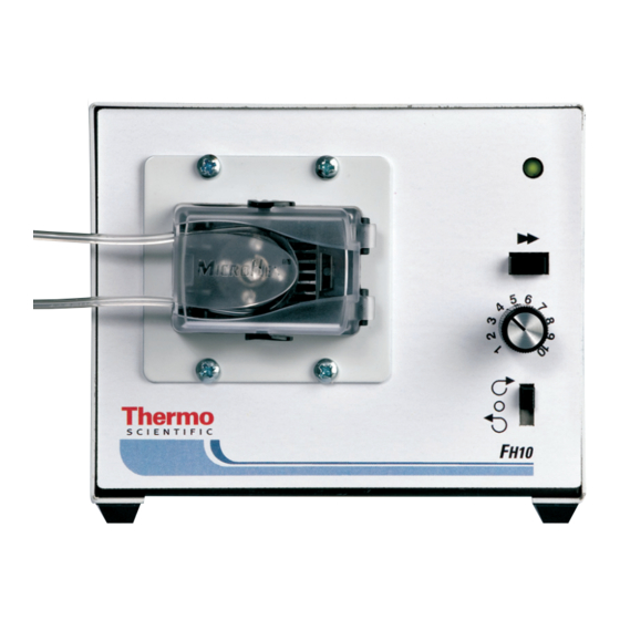
- Page 1 FH10 ® PUMP SYSTEM Operating Manual Model Number 72-310-010 72-310-080 72-310-300 A-1299-7099 First Edition...
- Page 2 These products are covered by one or more of the following U.S. and corresponding foreign patents: D605,286S Trademarks bearing the symbol in this publication are registered in the U.S. and in other countries. ® A-1299-7099 16696 091202 First Edition ECR/ECN DATE DESCRIPTION Thermo Scientific FH10 MICROFLEX ® Pump System Operating Manual...
- Page 3 These products are not designed for, nor intended for use in patient connected applications; including, but not limited to, Product Use medical and dental use, and accordingly have not been submitted for FDA approval. Limitation Thermo Scientific FH10 MICROFLEX ® Pump System Operating Manual...
-
Page 5: Table Of Contents
Tubing Flow Rates ..........8-2 Thermo Scientific FH10 MICROFLEX ®... - Page 7 Closing Occlusion Bed ......... . .2-3 Thermo Scientific FH10 MICROFLEX ®...
-
Page 9: Introduction
The Pump Head rotor contains four rollers for minimum pulsation. All units operate from an external DC power supply. The AC models are supplied with a Universal Power Supply, which provides a DC output for connection to the pump drive. Thermo Scientific FH10 MICROFLEX ® Pump System Operating Manual... - Page 10 4-terminal barrier strip for connection of Remote Start/Stop and for a Backup DC supply. DC Power Input, 2.5 mm Coaxial Receptacle Backup Input Remote Start/Stop Input Shorting Bar Figure 1-3. Pump – Rear Panel FH10 MICROFLEX ® Pump System Operating Manual Thermo Scientific...
-
Page 11: Installation And Setup
2. Rotate the Pump Head by turning it in the orientation desired. DO NOT PULL OUT THE PUMP, only rotate it. Some resistance to rotation will be felt. 3. Reinstall the 4 screws into the pump mounting plate and tighten. Thermo Scientific FH10 MICROFLEX ® Pump System Operating Manual... -
Page 12: Installing Tubing In Pump Head
Rollers, Figure 2-1, making sure that the tubing is centered on the Rollers and keeping the free ends of the tubing outside of the Tubing Retainers, Figure 2-1. FH10 MICROFLEX ® Pump System Operating Manual Thermo Scientific... - Page 13 Damage to the tabs may occur. 7. Close the door. The Locking Tabs must be on the outside of the door and the door fully closed for proper operation. Thermo Scientific FH10 MICROFLEX ® Pump System Operating Manual...
-
Page 14: Connecting Primary Power
3 and 4. A closure of the remote control switch contacts will start the Pump System. Opening the contact will stop the Pump System. FH10 MICROFLEX ® Pump System Operating Manual Thermo Scientific... -
Page 15: Operation
Approximately two feet of tubing length can be filled or emptied per minute using the push button on the 10 rpm units. Thermo Scientific FH10 MICROFLEX ® Pump System Operating Manual... -
Page 17: Maintenance
DANGER: Remove power from the Pump System before any cleaning operation is started. Clean exterior surfaces of case, control panel and pump rollers using a dry or damp cloth. Never immerse nor use excessive fluid. Thermo Scientific FH10 MICROFLEX ® Pump System Operating Manual... -
Page 19: Replacement Parts And Accessories
Replacement Parts and Accessories Section 5 Replacement Parts Description Part No. Knob 110199 Shorting Bar A-4402 Door 108229 Accessories Description Part No. Universal Power Supply 100-240V AC 77200-07 Thermo Scientific FH10 MICROFLEX ® Pump System Operating Manual... -
Page 21: Specifications
Installation Category: Model: 72-310-010, 72-310-080 Category II per IEC664 and 72-310-300 (Local level—appliances, portable equipment, etc.) Remote Start/Stop: Contact Closure connection at terminal strip contacts 3 and 4 Thermo Scientific FH10 MICROFLEX ® Pump System Operating Manual... - Page 22 EN61326-1/A2: 2001 (EMC Directive) 2002/95/EC (RoHS Directive) Converter is UL, cUL listed and CE, CCC approved. Regulatory agency specifications not applicable to the balance of the unit due to low voltage. FH10 MICROFLEX ® Pump System Operating Manual Thermo Scientific...
-
Page 23: Warranty, Product Return And Technical Assistance
WARRANTY. IN NO EVENT SHALL THE MANUFACTURER OR DISTRIBUTOR BE LIABLE FOR INCIDENTAL, INDIRECT, SPECIAL OR CONSEQUENTIAL DAMAGES. The warranty period for this product is one (1) year from date of purchase. Thermo Scientific FH10 MICROFLEX ® Pump System Operating Manual... -
Page 24: Product Return
Any damages resulting from improper packaging are your responsibility. If you have any questions about the use of this product, contact the Technical Assistance Manufacturer or authorized seller. FH10 MICROFLEX ® Pump System Operating Manual Thermo Scientific... -
Page 25: Available Microbore Autoanalysis Tubing
0.060 (1.52) 0.065 (1.65) 0.073 (1.85) 0.081 (2.06) 0.090 (2.29) 0.100 (2.54) 0.110 (2.79) NOTE: White indicates Available Black indicates Not Available Dark Gray indicates Special Order – check with factory. Thermo Scientific FH10 MICROFLEX ® Pump System Operating Manual... -
Page 26: Tubing Flow Rates
0.081 (2.06) 1050 8500 35200 0.090 (2.29) 1250 9350 41000 0.100 (2.54) 1450 10200 46200 0.110 (2.79) 1650 11000 50000 All flow rates based on pumping water @ 0 psig 70°F (21°C). FH10 MICROFLEX ® Pump System Operating Manual Thermo Scientific... - Page 28 9001 Thermo Fisher Scientific REGISTERED SUPPLIER 28W092 Commercial Ave. Barrington, Illinois U.S.A. 60010-2392 1-800-637-3739 (U.S. and Canada only) 11 (847) 381-7050 (Outside U.S.) (847) 381-7050 (Local) www.thermo.com fluidhandling@thermofisher.com...
Need help?
Do you have a question about the Microflex FH10 and is the answer not in the manual?
Questions and answers