
Related Manuals for Emerson IEC 62591


Summary of Contents for Emerson IEC 62591
- Page 1 Part Number D301709X012 October 2019 IEC 62591 Wireless Interface Instruction ® Manual (for ControlWave Micro) Remote Automation Solutions...
- Page 2 Emerson office. You can also receive the same quality training via our live, interactive Emerson Virtual Classroom and save on travel costs. For our complete schedule and further information, contact the Remote Automation Solutions Training Department at 800-338-8158 or email us at education@emerson.com.
-
Page 3: Table Of Contents
IEC 62591 Wireless Interface Instruction Manual (for ControlWave Micro) Contents Chapter 1 – General Information Scope of Manual ..........................1-2 Hardware ............................1-2 1.2.1 IEC 62591 Wireless Interface Module ................1-2 1.2.2 Emerson Wireless 781 Field Link ..................1-3 1.2.3 WirelessHART Field Devices ..................... - Page 4 Identify which Components of the System Are Working ............. 4-2 4.2.2 Basic Items to Check for Hardware ..................4-3 4.2.3 Checking Error/Status Codes in the Standard IEC 62591 Application ....... 4-3 Troubleshooting Checklist ....................... 4-7 Best Practices ..........................4-8 Data Updates ..........................4-9 Appendix A –...
-
Page 5: Chapter 1 - General Information
1.2.3 WirelessHART Field Devices ..........1-4 Configuration/Commissioning Software ..........1-5 Additional Technical Information ............1-5 This manual covers both the hardware – the IEC 62591 Wireless ™ Interface module for the ControlWave Micro device and the Emerson Wireless 781 Field Link (“Field Link”) and the software you need to configure and commission the hardware components. -
Page 6: Scope Of Manual
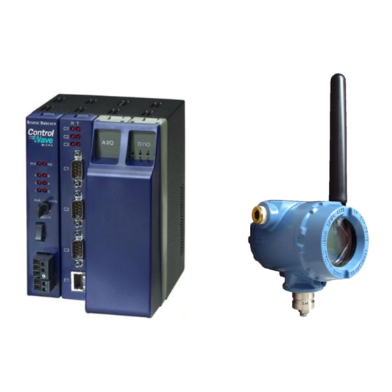
Chapter 4 Provides general troubleshooting tips. Troubleshooting 1.2 Hardware The IEC 62591 Wireless Interface has two basic components: the IEC 62591 Wireless Interface module (“module”) and the Field Link. 1.2.1 IEC 62591 Wireless Interface Module The IEC 62591 module has the standard appearance of a ControlWave Micro module (see Figure 1-2). -
Page 7: Emerson Wireless 781 Field Link
Micro except, due to a mechanical restriction, it cannot reside in the last slot of any housing. Each ControlWave Micro can support only one IEC 62591 Wireless Interface module. You cannot use the IEC 62591 with the ControlWave Micro Distributed I/O System. : For information on installing modules in the ControlWave... -
Page 8: Wirelesshart Field Devices
WirelessHART field devices. Remote Automation Solutions supports transmitters that conform to the WirelessHART protocol. The physical configuration of the IEC 62591 Wireless Interface is based on the ControlWave Micro and the total number of field devices. A ControlWave Micro implementation supports up to 100 devices. -
Page 9: Configuration/Commissioning Software
IEC 62591 Wireless Interface Instruction Manual (for ControlWave Micro) 1.3 Configuration/Commissioning Software Once you have installed the modules and wired them to the Field Link, use ControlWave Designer, AMS® Device Configurator, or a hand-held HART configurator (such as the 375 or 475 Field Communicator or the ™... - Page 10 IEC 62591 Wireless Interface Instruction Manual (for ControlWave Micro) [This page is intentionally left blank.] General Information Revised October-2019...
-
Page 11: Chapter 2 - Installation
Module Firmware V1.20 or later to support new Burst and Event parameters. ▪ You can install the IEC 62591 module in any I/O slot (slot 3 or higher except for the last slot in any chassis/housing) in the ControlWave Micro. You cannot use the IEC 62591 with the ControlWave Micro Distributed I/O System. -
Page 12: Installing The Field Link
IEC 62591 Wireless Interface Instruction Manual (for ControlWave Micro) Restore power to the unit. 2.2 Installing the Field Link This section covers where and how to install the Field Link. 2.2.1 Optimizing the Location Mount the Field Link in a location that provides convenient access to the host system network (wireless I/O devices) and the network of wireless field devices. -
Page 13: Mounting The Field Link
Use a ½-in. socket-head wrench to fasten the nuts to the U-bolt. Figure 2-3. Field Link Mounting 2.3 Wiring the Module and Field Link This section assumes you have already installed the IEC 62591 module in the ControlWave Micro and installed the Field Link in its permanent field location. -
Page 14: Wiring The Field Link
Field Link meets all appropriate local requirements (use of conduit, etc.). 2.3.1 Wiring the Field Link Power down the IEC 62591 module (if it is currently powered). Remove the housing cover identified on the casing as “Field Terminals.”... - Page 15 IEC 62591 Wireless Interface Instruction Manual (for ControlWave Micro) Table 2-1. RS-485 Cable Connections Field Link IEC 62591 Module A(+) B(-) POWER - POWER + POWER B(-) Twisted Pair 1 18 AWG 2-Twisted Shielded Pairs Cable Twisted Pair 2 Figure 2-5. IEC 62591 Module Power and Data Wiring...
-
Page 16: Configuring Wireless Devices For The Network
IEC 62591 Wireless Interface Instruction Manual (for ControlWave Micro) Termination Jumpers Figure 2-6. IEC 62591 Module – Connecting Termination Jumpers 2.4 Configuring Wireless Devices for the Network See the product data sheet (available on our website) for a list of devices Emerson has tested with the IEC 62591 Wireless Interface. - Page 17 IEC 62591 Wireless Interface Instruction Manual (for ControlWave Micro) Basic instructions for setting the long tag, Network ID and Join Key using the 375 Field Communicator are included below; see the Field Communicator user manual if you need more information.
- Page 18 IEC 62591 Wireless Interface Instruction Manual (for ControlWave Micro) From the Manual Setup Menu, double-tap Wireless. Manual Setup Wirelessnnnn nnnnnnnnnnnnnnnnnnnn 2 Process Sensor 3 Percent of Range 4 Device Temperatures 5 Device Information 6 Device Display 7 Other From the Wireless Menu, double-tap either: a.
-
Page 19: Preparing For Configuration And Commissioning
IEC 62591 Wireless Interface Instruction Manual (for ControlWave Micro) 2.5 Preparing for Configuration and Commissioning Once you have completed the wiring between the Field Link and the ControlWave Micro, re-attach the plastic bezel covers and apply power to the ControlWave Micro. - Page 20 IEC 62591 Wireless Interface Instruction Manual (for ControlWave Micro) [This page is intentionally left blank.] 2-10 Installation Revised October-2019...
-
Page 21: Chapter 3 - Configuration And Commissioning
Upgrading Firmware in the IEC 62591 Wireless Interface Module ................... 3-20 In addition to wiring the Field Link to the IEC 62591 module and applying power to the module, you need to configure your ControlWave project to access the wireless network so it can discover and commission each WirelessHART device in the entire network. -
Page 22: Overview
3.1 Overview As indicated previously, a wireless interface network consists of a number of wireless devices, a Field Link, and an IEC 62591 module installed in a ControlWave Micro. The IEC 62591 module can communicate with a maximum of 100 wireless devices; the actual number allowed for a given application varies depending upon the burst rate. -
Page 23: Network Id And Join Key
IEC 62591 Wireless Interface Instruction Manual (for ControlWave Micro) During the configuration, you identify the Network ID to which the device eventually belongs and provide the network-specific Join Key (see Network ID and Join Key). During configuration, you must also give the wireless device a unique long tag name based on its use or location (such as PMP1TEMP, PMP2PRES, or WEL02LVL). -
Page 24: Active List And Commission List
3.1.4 Active List and Commission List When the Field Link detects a wireless device that has the correct Network ID and Join Key, the IEC 62591 program running in the ControlWave Micro stores information about that device in a structure called the Active List. -
Page 25: Before You Begin
IEC 62591 Wireless Interface Instruction Manual (for ControlWave Micro) 3.2.1 Before You Begin : Some of the structure data types used in the IEC 62591 sample Note programs have changed over time to add functionality. In particular, ControlWave Micro firmware version 5.80 includes modifications for burst and event functionality for newly released transmitters. - Page 26 IEC 62591 Wireless Interface Instruction Manual (for ControlWave Micro) If not already there, navigate to the OpenBSI/Projects area and open one of the IEC62591 sample projects. Table 3-1. IEC 62591 Sample Programs Sample Program Name Description IEC62591_V1_20_Example.zwt; Additional support for Burst Msg0 and Burst Msg1 for newer transmitters with CW Micro Firmware EC62591_V1_20_Example.zwt...
-
Page 27: Modifying The Iec62591_Structs Datatypes Worksheet
The IEC62591_STRUCTS datatypes worksheet defines the data types used by the program. Double-click the IEC62591_STRUCTS worksheet to open it. Do not modify the datatypes themselves or your IEC 62591 program will Caution not function correctly. You should only define the sizes of specific arrays. -
Page 28: Active_Devices_Array_V1_20 Datatype
IEC 62591 Wireless Interface Instruction Manual (for ControlWave Micro) You only modify the sizes of the array data types – these sizes vary depending upon the number of devices in the wireless network. ACTIVE_DEVICES_ARRAY_V1_20 datatype The ACTIVE_DEVICES_ARRAY_V1_20 datatype defines an array of... -
Page 29: Inactive_Stat_Array And Last_State_Array Datatypes
IEC 62591 Wireless Interface Instruction Manual (for ControlWave Micro) Notes: ▪ COMMISSION_ARRAY_V1_20, and COMMISSION_POINT_ V1_20 datatypes are used in the IEC62591_V1_20_Example.zwt project. These structures provide for new transmitter controls. (5.80 or newer ControlWave Micro firmware) ▪ COMMISSION_ARRAY_DISCRETE, and COMMISSION_POINT_DISCRETE datatypes are used in the IEC62591_DIO_Example.zwt project. -
Page 30: Errorcatch Function Block (Optional)
The various structures in the IEC 62591 program are maintained internally; they cannot be collected by external utilities such as DataView. To support this sort of data collection, the IEC 62591 program does include a special function block (DevData) that copies specific device data from the Commission array to a LIST structure that can be collected by an external program such as DataView. -
Page 31: Modifying The Act_List Function Block (Optional)
IEC 62591 Wireless Interface Instruction Manual (for ControlWave Micro) For example, if you decided that you didn’t want the Slot3Var, and instead you wanted the serial number of the device you would do the following: Change the ianyElement10 entry in the LIST structure to reference SerialNum instead of slot3Var. - Page 32 IEC 62591 Wireless Interface Instruction Manual (for ControlWave Micro) maximum of ten devices (defined by two elements for the tag name and device ID) in the active list. You can change this if you need to. To do this, double-click the Act_List worksheet to open it.
-
Page 33: Configuring The Commission List
IEC 62591 Wireless Interface Instruction Manual (for ControlWave Micro) listStatus := LIST100_1.odiStatus; If you need to support the maximum number of devices – 100 – you can do this by chaining together two LIST100 function blocks. To do this, you just use the same iiListNumber parameter for each; that connects the two to allow for a 200 element list. - Page 34 You must create an entry in the Commission List that includes the long tag name for the device and decommission flag (set to FALSE) for each and every device you want the IEC 62591 module to access. To do this, double-click the CommisList (or Clist) worksheet to open it,...
-
Page 35: Specifying The Join Key
In the same worksheet you use the IEC62591_SLOT variable to specify the slot number of the ControlWave Micro controller that holds the IEC 62591 module. The IEC 62591 module can reside in any open I/O slot (slot 3 or higher) except for the last slot in the chassis. -
Page 36: Generating Alarms Based On Iec62591 Function Block Status (Optional)
For example, beginning with 1.01 IEC 62591 module firmware, odiStatus codes in the range -51120 to -51129 indicate the IEC 62591 Wireless Interface Module had to re-start and cannot provide live data updates until the re-start process is complete. You could add the code... -
Page 37: Additional Programming Notes
ALARM_LOGICAL_ON_1 iaAlarmVar:=bXMTRFrozen, 3.2.12 Additional Programming Notes The IEC 62591 example program includes two required program type POUs. One called “InitList” initializes the Commission List. The other called “WiLess” uses the Wireless worksheet definitions and includes the actual IEC62591 function block. -
Page 38: Active Advertising
(or replaced) wireless devices. Because leaving radios on consumes power, active advertising is only used under certain conditions: ▪ When the IEC 62591 module is first powered on, or is restarted after being powered off, it automatically remains in active advertising mode for a period of time to detect wireless devices. -
Page 39: Wirelesshart Data Access And Statistics
IEC 62591 Wireless Interface Instruction Manual (for ControlWave Micro) If you only want to replace a device, for example, because it failed and you want to put an identical device in the same location, there is no need to decommission the device; simply use the Field Tools’ AMS Device... -
Page 40: Wirelesshart Communication Statistics
▪ The application you create must handle the PV validity flags. For example, the IEC 62591 module reports the flag but does not set the PVs to NAN. It is up to the application to choose whether to force a NAN value, use the failsafe value, or use the last reported good value. - Page 41 IEC 62591 Wireless Interface Instruction Manual (for ControlWave Micro) Using DataView or through ControlWave Designer in online operation, change the value of the ioaiMode parameter to 2 to start the firmware download. Monitor the odiStatus parameter on the IEC62591 function block.
- Page 42 IEC 62591 Wireless Interface Instruction Manual (for ControlWave Micro) [This page is intentionally left blank.] 3-22 Configuration and Commissioning Revised October-2019...
-
Page 43: Chapter 4 - Troubleshooting
IEC 62591 Wireless Interface Instruction Manual (for ControlWave Micro) Chapter 4 – Troubleshooting In This Chapter Troubleshooting Guidelines ............. 4-1 Common Troubleshooting Techniques ..........4-2 4.2.1 Identify which Components of the System Are Working ..4-2 4.2.2 Basic Items to Check for Hardware ........4-3 4.2.3 Checking Error/Status Codes in the Standard IEC 62591... -
Page 44: Common Troubleshooting Techniques
▪ The IEC 62591 application (ControlWave project) running in the ControlWave Micro ▪ ControlWave Designer software, and AMS Device Configurator running in the PC or laptop ▪ IEC 62591 protocol software running in the Field Link and in all of the wireless devices Troubleshooting Revised October-2019... -
Page 45: Basic Items To Check For Hardware
IEC 62591 Wireless Interface Instruction Manual (for ControlWave Micro) Figure 4-1. Wireless Interface 4.2.2 Basic Items to Check for Hardware ▪ Ensure power is connected. ▪ Check that all modules are properly seated in slots. ▪ Ensure cable connections are good between the field link and controller, and between the PC/laptop and the controller. - Page 46 Click Online > Debug. Double-click on the wireless* program worksheet. Scroll down through the worksheet until you see the IEC 62591 function block. (You’ll notice that in Debug Mode, a column of live values sits to the left of the program statements; these are the actual parameter values in the program as it executes in the ControlWave Micro.)
- Page 47 IEC 62591 Wireless Interface Instruction Manual (for ControlWave Micro) Column of live values odiStatus parameter odiStatus value of IEC62591 function block Figure 4-3. Wireless Program Worksheet Find the odiStatus parameter for the IEC62591 function block. (Figure 4-3 shows this; in this particular example, the parameter has a variable name of IEC62591Status;...
- Page 48 For “-51012” the error says: Figure 4-7. Example of Error Message That means the IEC 62591 function block does not detect an IEC 62591 Wireless Interface module in the specified slot. This happens if you...
-
Page 49: Troubleshooting Checklist
Did you assign a unique Long Tag Name to each wireless device and specify the exact same long tag names in the IEC 62591 application running in the ControlWave Micro? If not, use Field Tools’... -
Page 50: Best Practices
Are any status LEDs lit on the ControlWave Micro PSSM module? If so, consult the ControlWave Micro instruction manual for more information. Did you check for error/status codes in the IEC 62591 application? If not, follow the instructions in Section 4.2.3. 4.4 Best Practices... -
Page 51: Data Updates
4.5 Data Updates If you notice that data updates for process variables are slow, this can occur if the IEC 62591 device cannot process a data request fast enough. If this happens it generates a delayed response message, and the RTU re-requests the data. - Page 52 IEC 62591 Wireless Interface Instruction Manual (for ControlWave Micro) [This page is intentionally left blank.] 4-10 Troubleshooting Revised October-2019...
-
Page 53: Appendix A - Glossary
Active A mode in which the IEC 62591 module sends messages to the wireless network to Advertising keep radios active for a longer period of time to facilitate quicker detection of new (or replaced) wireless devices. - Page 54 IEC 62591 Wireless Interface Instruction Manual (for ControlWave Micro) (continued) ControlWave A brand name for a family of controllers (RTUs) and flow computers available from Emerson. ControlWave A software configuration tool that lets you create programming logic for the Designer ControlWave controller or flow computer.
- Page 55 IEC 62591 Wireless Interface Instruction Manual (for ControlWave Micro) (continued) Frequency Shift Keypad. Gigahertz, 10 cycles per second Electrical ground, such as used by the RTU’s power supply. Gauge Pressure. A Foundation Fieldbus protocol operating at 31.25 kbit/s that interconnects field devices (such as sensors or I/O devices).
- Page 56 IEC 62591 Wireless Interface Instruction Manual (for ControlWave Micro) Kilobytes. KiloHertz. Liquid Crystal Display. Light-Emitting Diode. A status light. Long Tag A name (up to 32 characters) for a device in the wireless network. Each device in the wireless network must have a unique long tag, different from all other devices in the network.
- Page 57 IEC 62591 Wireless Interface Instruction Manual (for ControlWave Micro) P, Q Parameter A property of a point that typically can be configured or set. For example, the Point Tag ID is a parameter of an Analog Input point. Parameters are normally edited by using configuration software running on a PC.
- Page 58 IEC 62591 Wireless Interface Instruction Manual (for ControlWave Micro) (continued) SRAM Static Random Access Memory. Stores data as long as power is applied; typically backed up by a lithium battery. TCP/IP Transmission Control Protocol/Internet Protocol. Flowing temperature. TX or TXD Transmitted Data communications signal.
- Page 59 IEC 62591 Wireless Interface Instruction Manual (for ControlWave Micro) [This page is intentionally left blank.] Revised October-2019 Glossary...
- Page 60 Emerson Automation Solutions Remote Automation Solutions Emerson FZE P.O. Box 17033 © 2012–2019 Remote Automation Solutions, a business unit of Emerson Automation Jebel Ali Free Zone – South 2 Solutions. All rights reserved. Dubai U.A.E. This publication is for informational purposes only. While every effort has been made to ensure...
Need help?
Do you have a question about the IEC 62591 and is the answer not in the manual?
Questions and answers