
Related Manuals for Lincoln Electric MASTERPIPE Mini Profiler


Summary of Contents for Lincoln Electric MASTERPIPE Mini Profiler
- Page 1 ® MASTERPIPE Mini Profiler Installation and Operations Guide February 11, 2014 Copyright 2013-2014 by Vernon Tool Company...
- Page 2 Published by: Lincoln Electric Cutting Systems Torchmate Distribution Center 1170 Trademark Drive, #101 Reno, NV 89521 www.torchmate.com Copyright © 2013-2014 by Vernon Tool Company All rights reserved. Reproduction of this work, in whole or in part, without written permission of the publisher is prohibited.
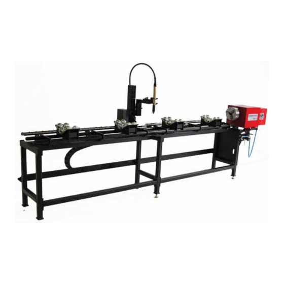
- Page 3 ® MASTERPIPE Mini Profiler (MPMP) Base machine and single add-on section cutting 8” I.D. pipe Installation and Operations Guide...
-
Page 4: Table Of Contents
Table of contents Statement of warranty ..... vi Welcome to Torchmate ..... viii Safety Information . - Page 5 Step 26: Load material for speed and demo cuts ..45 Step 27: Load the speed test cut file....46 Step 28: Adjust torch position for speed test cut ..47 Step 29: Set the pierce delay.
-
Page 6: Statement Of Warranty
Buyer will pay for the cost of Shipping to and from the Seller for all warranty repairs. Before returning any goods, please contact Lincoln Electric Cutting Systems Technical Support. Call Monday through Friday from 6:30 AM to 4:00 PM Pacific Time. Toll Free: 1-866-571-1066 x3... - Page 7 Any claim by Buyer with reference to the Goods sold hereunder shall be deemed waived by the Buyer unless submitted in writing to seller within the earlier of (i) thirty (30) days following the date Buyer discovered or by reasonable inspection should have discovered, any claimed breach of foregoing warranty, or (ii) 12 months following the date of shipment.
-
Page 8: Welcome To Torchmate
Welcome to Torchmate Welcome Letter To the newest member of our Torchmate Family: Thank You! Thank you for putting your faith and trust in Torchmate. When you purchased your Torchmate CNC Cutting System, you pur- chased more than just a machine. You purchased a team. The Torch- mate team was built with the goal in mind of helping you get the most value out of your automation investment. -
Page 9: Safety Information
Safety Information Safety Guide... -
Page 10: Safety First
Safety First Lincoln Electric Cutting Systems equipment is designed and built with safety in mind. However, your overall safety can be increased by proper installation ... and thoughtful operation on your part. PROTECT YOURSELF AND OTHERS FROM POSSIBLE SERIOUS INJURY OR WARNING DEATH. - Page 11 ARC RAYS can burn. Arc rays Plasma Arc Rays can injure your eyes and burn your skin. The plasma arc process produces very bright ultraviolet and infrared rays. These will damage your eyes and burn your skin if you are not properly protected.
- Page 12 Safety First (continued) The operation of plasma cutting or gouging fume control equipment is affected by various factors including proper use and positioning of the equipment, maintenance of the equipment, and the specific procedure and application involved. Worker exposure levels should be checked upon installation and periodically thereafter to be certain levels are within applicable OSHA PEL and ACGIH TLV limits.
- Page 13 Be sure there are no combustible or flammable materials in the workplace. Any material that cannot be removed must be protected. 4.4.1 Sparks and hot materials from cutting or gouging can easily go through small cracks and openings to adjacent areas. 4.4.2 Avoid cutting or gouging near hydraulic lines.
- Page 14 Safety First (continued) Read and follow the instructions on compressed gas cylinders, associated equipment, and CGA publication P-l, “Precautions for Safe Handling of Compressed Gases in Cylinders,”available from the Compressed Gas Association 1235 Jefferson Davis Highway, Arlington, VA 22202. Electrical power FOR ELECTRICALLY powered equipment.
- Page 15 AUTOMATIC OPERATION Automatic operation Any CNC machine may begin to operate automatically without warning. Only a trained individual familiar with the software, machine, and computer system should operate this equipment. Keep the immediate area around the CNC machine clear of materials that may cause interference.
- Page 16 Safety First (continued) 13.3 When the end of a CNC machine’s travel creates a “hard stop,” it creates a crush point. Keep fingers and hands away from this. 13.4 Do not stack or store any additional items in contact with the machine.
- Page 17 Refer to the following standards or their latest revisions for more information: PUBLICATIONS • OSHA, SAFETY AND HEALTH STANDARDS, 29CFR 1910, obtainable from the Superintendent of Documents, U.S. Government Printing Office, Washington, D.C. 20402 • ANSI Standard Z49.1, SAFETY IN WELDING AND CUTTING, obtainable from the American Welding Society, 550 N.W.
- Page 18 Technical Support Call, fax, or email When making the connections and setting up the table if a question or concern arises or a part seems to be missing, please contact Torchmate technical support. Technical support will also help you with operating the CNC system, and troubleshooting problems.
-
Page 19: Hardware Installation
Hardware Installation Installation and Operations Guide... -
Page 20: Parts And Assemblies Checklist
Parts and assemblies checklist The parts included in your MASTERPIPE ® Mini Profiler System (MPMP) shipment are listed here in the order you will assemble them. To make it easier to complete the assembly of your cutting system, lay out the received parts in this order as you check them against this list. Qty. - Page 21 Qty. Part Description Part Number Step Spirit level (or similar leveling instrument) (from your toolbox) Divider calipers (or similar instrument) (from your toolbox) C-clamps (or similar clamps) (from your toolbox) Small section of gear rack (used as an 08-0013-0015 alignment tool) Torch mount carrier assembly TMS-140-0001-05 (part of horizontal drive unit)
- Page 22 Parts and assemblies checklist (continued) Qty. Part Description Part Number Step Small tube support cradle TMS-050-0001-02 (optional 2 per section) Torch lead from plasma cutter (or (separate purchase) oxy-fuel torch lines) Y-Motor cable 08-0005-050XLR 15, 16 Cable ties (from your toolbox or separate purchase) Air supply hose (from the shop air...
- Page 23 Qty. Part Description Part Number Step Chuck key (included with base machine) Plasma cutter with cut charts (seperate purchase -- Kaliburn Dagger 100 shown here) Installation and Operations Guide...
-
Page 24: Feature Overview
Feature overview These features of the MASTERPIPE ® Mini Profiler help to make this CNC cutting system versatile, flexible, reliable, and economical. Torch travels on 5-ft • The base machine gives you everything you need to begin cutting. The system base machine with is shipped pre-assembled, so you leveling feet... - Page 25 Vertical chuck-height • To adjust the chuck for different size Adjustment pipe, loosen the locking levers and move the gas-cylinder supported mount with ease. Loosely chuck the material in the new the position, jog the material to rotate and cetner it, lock the vertical and cut.
-
Page 26: Installation Overview
Installation overview When installing a MASTERPIPE Mini Profiler, there are many factors that will influence the potential productivity and ease of use of the machine. The main factors include the physical layout and placement of the machine in the shop and the availablity of power, compressed air and other gases, and ventilation. - Page 27 • Recognize that smoke and dust are created by the cutting processes. Fumes Plan to remove it and to provide a supply of clean air. The Lincoln Electric Modular Extraction Hood can remove dust and smoke from cutting.
-
Page 28: Step 1: Locate And Place The Base Machine
Step 1: Locate and place the base machine The MASTERPIPE® Mini Profiler base machine is completely assembled. After considering the factors discussed in the previous pages, place the base machine in the desired location. Required parts / Part Description Part # components MPMP Base TMS-050-0005-01... -
Page 29: Step 2: Attach (Optional) Add-On Sections
Step 2: Attach (optional) add-on sections If add-on sections have been ordered, un-crate them and loosely attach them to the base unit. Later steps for leveling and alignment will include tightening the fasteners. Required parts / Part Description Part # components MPMP Base From Step 1... -
Page 30: Step 3: Install The Rails
Step 3: Install the rails The MASTERPIPE ® Mini Profiler base machine is nearly completely assembled when it is de- livered. If it is not already mounted, install the rails carrier (with the gear rack and V-rails) next. If the rails are already in place, attach the rail connector plates, then go to Step 4. Required parts / Part Description... -
Page 31: Step 4: Attach Cable Trays
Step 4: Attach cable trays When, in a later step, the cable carrier links are added, they are supported by trays. If the han- gars are not already installed, use the screws and washers to attach the hangers to the legs of the base machine and any add-on sections. -
Page 32: Step 5: Level The Section(S)
Step 5: Level the section(s) The base machine (and any add-on sections) must be leveled to allow the profiler to work most efficiently and accurately. Use the leveling feet and a spirit level to bring the module(s) level across their width and along their length. Required parts / Part Description... -
Page 33: Step 6: Align The Sections
Step 6: Align the sections If you have only the base machine, skip ahead to Step 8. Add-on sections (optional) must be aligned with the base machine for accurate and reliable operation during cutting. A taut string and dividers will allow you to adjust the position of the modules to align them. Required parts / Part Description... -
Page 34: Step 7: Align Any Add-On Section Gear Racks
Step 7: Align any add-on section gear racks If you have only the base machine, skip ahead to Step 8. The torch holder moves along the rail by means of a motor-driven gear. The gear engages a gear rack mounted below the rail. In order for the torch to move smoothly and accurately from one module to the next, the gear racks on adjacent modules must be aligned. -
Page 35: Step 8: Install The Horizontal Drive Unit
Step 8: Install the horizontal drive unit If the horizontal drive unit is pre-installed, it may still require adjustment to properly engage the gear rack. The horizontal drive unit holds the torch and moves it along the pipe length us- ing V-rails, gear racks, and a motor / gear box assembly. -
Page 36: Step 9: Add Hard Stops
Step 9: Add hard stops If the hard stops are pre-installed, skip ahead to Step 10. The Y-axis hard stops prevent oper- ational problems from sending the torch beyond the end of the rail. Attach the hard stops at the extreme ends of the rail support plate, using the same threaded holes that are used for the rail connector plates (used between table add on sections and the base machine). -
Page 37: Step 10: Install (Optional) Avhc Torch Mount
Step 10: Install (optional) AVHC torch mount If you are not using an (optional) AVHC torch mount, or your AVHC torch mount has been pre-installed, skip to step 11. The AVHC torch mount is a part of the horizontal drive unit, de- scribed in Step 8. -
Page 38: Step 11: Install (Optional) Oxy-Fuel Torch Mount
Step 11: Install (optional) oxy-fuel torch mount If you are not using an (optional) oxy-fuel torch mount, skip to Step 13. If your oxy-fuel torch mount is pre-installed, skip to Step 12. If the oxy-fuel torch is not already installed, attach the mount to the horizontal drive unit, described in Step 8. -
Page 39: Step 12: Install (Optional) Oxy-Fuel Relay
Step 12: Install (optional) oxy-fuel relay If your MASTERPIPE Mini Profiler is equipped with the optional oxy-fuel torch, the CNC con- troller will control cutting oxygen solenoid by means of a Torchmate Universal Interface Relay. Required parts / Part Description... -
Page 40: Step 13: Install Cradles And Catch Trays
Step 13: Install cradles and catch trays Ball transfer cradles are supports for the pipe or tube being cut. They rest upon the module tubes and can be re-positioned along the module length for better support and to get them out of the way of cutting sparks and spatter. -
Page 41: Step 14: Install (Optional) Small Pipe Cradles
Step 14: Install (optional) small pipe cradles Small pipe cradles are supports specifically designed for smaller diameter material. If most material is 2” I.D. or under, the small pipe cradle may be appropriate. Small pipe cradles, like the ball transfer cradles, rest upon the frame tubes. They can be re-positioned along the length for better support and to get them out of the way of cutting sparks and spatter. -
Page 42: Step 15: Route Cables Through Cable Carrier
Step 15: Route cables through cable carrier The cable carrier system consists of a number of snap-together links, each with a snap-down cover. It also includes a support tray and end-brackets. With the covers snapped-up, the motor cable, plasma torch cable, and (optional) oxyfuel hoses are safely placed in the cable carrier links which routes them to the torch carrier. -
Page 43: Step 16: Connect Motor Cable To Chuck Motor
Step 16: Connect motor cable to chuck motor The chuck motor’s cable (X-motor cable) is routed out from the chuck box through a strain re- lief, a wear grommet, and out to the CNC controller. If the X-motor cable has not been routed, connect it to the motor pigtail. -
Page 44: Step 17: Connect Air Lines
Step 17: Connect air lines The plasma cutter typically requires a supply of dry, oil-free, regulated compressed air. In addition, some plasma operations will use other types and pressures of different compressed gases. Ensure that you have the correct supplies connected to the plasma cutter and that the flow and pressure of the supply falls within the specified ranges. -
Page 45: Step 18: Connect Motor Cables To Cnc Controller
Step 18: Connect motor cables to CNC Controller The CNC Controller’s motor cables connect to the chuck motor (X-cable) and to the torch carrier motor (Y-cable). The XLR-type connectors provide a positive mechanical and electrical connection for both cables. Required parts / Part Description Part #... -
Page 46: Step 19: Connect Cnc Cable To Cnc Controller
Step 19: Connect CNC cable to CNC Controller The plasma cutter’s CNC interface cable connects to the relay terminals of the Torchmate CNC Controller. This connection allows the CNC Controller to operate the plasma cutter’s plasma arc under CNC control. Required parts / Part Description... -
Page 47: Step 20: Connect Cnc Cable To Avhc (Optional)
Step 20: Connect CNC cable to AVHC (optional) If the AVHC is installed, the AVHC Controller will connect both to the plasma cutter raw arc voltage terminals, its CNC interface cable (two wire pairs), and to the CNC Controller. In addi- tion, the lifter station motor cable runs to the AVHC Controller. -
Page 48: Step 21: Connect Computer To Cnc Controller
Step 21: Connect computer to CNC Controller The computer that runs your Driver software can be a desktop or a laptop. It connects to the CNC Controller with a standard USB printer cable. Required parts / Part Description Part # components Pro-series CNC 4 axis drive box... -
Page 49: Step 22: Install Tm4 Driver Software
Step 22: Install TM4 Driver software With your desktop or laptop computer setup, you can install the Torchmate Driver 4 software from the USB flash drive. Required parts / Part Description Part # components Laptop or PC with Microsoft From Step 21 Windows®... -
Page 50: Step 23: Load Configuration File
Step 23: Load configuration file The Torchmate Driver software has been used in a variety of cutting products. Each type of ® cutting system / tool combination has a different configuration file. The MASTERPIPE Mini Profiler comes with three configuration files to help tune the machine for various diameter pipe cutting jobs. -
Page 51: Step 24: Test Motor Jogging
Step 24: Test motor jogging Before pipe gets loaded onto the MPMP machine, you can test the operation by jogging the motors forward and backward in both the X and Y directions. Required parts / Part Description Part # components MPMP with CNC Con- From Step 20 troller... -
Page 52: Step 25: Set The Pipe Diameter
Step 25: Set the pipe diameter Three configuration files are supplied for the Torchmate Driver software for three different ranges of pipe diameter. This is so that the correct parameters may be set for accurately starting and stopping the motion of pipes of widely differing weights. Once the correct file is selected, the pipe diameter must be accurately specified inside the Driver software. -
Page 53: Step 26: Load Material For Speed And Demo Cuts
Step 26: Load material for speed and demo cuts Your MASTERPIPE Mini Profile can manage material from 1” to 8” in production work, so changing pipe diameter is important. For or speed and demo cuts, you will load a length of 6” I.D. -
Page 54: Step 27: Load The Speed Test Cut File
Step 27: Load the speed test cut file Cut charts for most plasma cutters give estimated speeds to use for initial MPMP cuts. To find the best cutting speed, you must evaluate the quality of cuts made at different speeds. Sever- al files are provided for speed test cutting with different speed ranges. -
Page 55: Step 28: Adjust Torch Position For Speed Test Cut
Step 28: Adjust torch position for speed test cut With the pipe to be cut on the rack and locked into the chuck, the torch position can be set. Make sure the torch is raised high enough to provide clearance and then use the jog buttons to bring the torch carrier over the pipe. -
Page 56: Step 29: Set The Pierce Delay
Step 29: Set the pierce delay A plasma cut that does not begin at the edge of the material being needs to complete its pierce before beginning the cut motion. The amount of delay to complete the pierce depends on the material type and thickness. Find the delay on the cut chart and set the value in the TM 4 output panel. -
Page 57: Step 30: Cut The Speed Test
Step 30: Cut the speed test With the pipe loaded on the machine, the speed test cut file loaded on the computer, the cor- rect consumables for the selected amperage, and the plasma cutter’s compressed gas supply available and its configuration set according to the cut charts, you are ready to cut the speed test. -
Page 58: Step 31: Analyze The Speed Test
Step 31: Analyze the speed test After the speed test cut(s) have been made, look over each cut and evaluate its bevel, dross, and completeness. Select the best cut speed / amperage / height combination. Keep records of the test results for future use. Required parts / Part Description... -
Page 59: Step 32: Load The Demo Cut File
Step 32: Load the demo cut file The demo file was designed using the optional WinMPM software (recommended). It illus- trates various types of cuts that the MPMP can make. Cutting the demo cut on the same material used for the speed test cuts allows you to evaluate the settings you have selected and make further adjustments. -
Page 60: Step 32: Set The Demo Cut Speed In G-Code
Step 32: Set the demo cut speed in G-code With the pipe ready to be cut, using the settings used for the line speed cuts, you need only set the speed that the line speed cuts gave the best quality. You can open the G-code editor and set the speed. -
Page 61: Step 33: Cut And Analyze The Demo Cut
Step 33: Cut and analyze the demo cut After editing the G-code to set the cutting speed, check the setup and cut the demo piece. When it cools, clean it up and inspect it. You may want to experiment with setting changes so that you find the optimum values for your material. - Page 62 MASTERPIPE ® Mini Profiler...
-
Page 63: Driver Introduction
Driver Introduction Driver Software... -
Page 64: Installing The Driver Software
Installing the Driver software This section illustrates the installation of the Torchmate 4 Driver software (TM4). This installation takes just a few minutes. The TM4 software enables your computer to com- municate instructions to your CNC Controller and all of the cutting operations on your CNC table or CNC pipe cutter. - Page 65 Illustrations (screen shots) of the TM4 installation pro- cess. Driver Software...
-
Page 66: Manually Installing The Device Drivers (If Necessary)
Manually installing the device drivers (if necessary) The hardware device driver is the software component of the TM4 system that talks directly to the CNC Controller hardware. While some computer operating systems will automatically install the driver using Plug-n-Play, in some cases the device driver must be installed manually. - Page 67 Illustrations (screen shots) of the device driver installa- tion process. Driver Software...
-
Page 68: Configure The Computer's Power Saving Feature
Configure the computer’s power saving feature Computers and particularly battery-powered laptop computers frequently come pre-con- figured to save energy by turning off the screen and putting the computer into a “sleep” mode if no keyboard or mouse activity is detected for a certain period. Since you don’t want your computer to go to sleep during cutting operations, you will want to disable this feature. - Page 69 Power options Control Panel Select Change when the computer sleeps Edit power plan settings Set both to Never Driver Software...
-
Page 70: Driver Software Configuration Setup Files
Driver software configuration setup files There are many configuration properties that can be set up to customize the way the TM4 software operates your CNC cutting system. You can change many of these prop- erties and then save the configuration setup in a file. You can reload the custom config- uration file at any time. - Page 71 Illustrations (screen shots) of the new configuration file selection and loading Provided setup files Torchmate1.stp is for Torchmate 1 (also called Torchmate Stan- dard CNC systems). Torchmate2.stp is for Torchmate 2 bolt together and kit tables. Torchmate3.stp is for Torchmate 3 bolt together and kit tables. TorchmateX.stp is for Torchmate X turn key and kit systems.
-
Page 72: Driver Software Panels
Driver software panels The Driver software screen is divided into panels. Each of these is identified briefly by its function and its location. Additional details are in the following sections. Instructions • After you open a setup file, the main Torchmate screen appears, containing all information needed to run the Torchmate table. - Page 73 CONNECTION VIEWPORT Illustration STATUS OUTPUT (screen shot) of the TM4 screen showing the location of the panels CURRENT CONTROL PANEL G-code CONTROL PANEL COORDINATES SELECTION Driver Software...
-
Page 74: Control Panel Descriptions
Control panel descriptions There are eight control panels in the TM4 software display screen. The color-coded Se- lection buttons to the left of the panels select the displayed function. Most setups use some (but not all) panels. • Green Buttons adjust settings or perform a non-moving/non-pausing Color codes action. - Page 75 • The Manual Data Input or MDI panel allows the execution or testing of G-code entered in the field. • The G-code in the MDI field overrides the currently loaded G-code file without altering it. • Start will start the code entered here, reset will jump back to the beginning, and hold will pause the code.
-
Page 76: Coordinates (Dro) Panel
Coordinates (DRO) panel The Digital Read Out (DRO) of coordinates shows the position of the tool. The values change as the tool moves. • The coordinates section--also called DRO (Digital Read Out)-- Program indicates the machine’s current position. Coordinates • The main coordinates are referred to as the Program coordinates, which show where the machine currently is relative to the program zero. - Page 77 Illustrations (screen shots) of the Coordinates panel To set the program zero point, jog the machine to the de- sired zero point and click Set. Zero All sets both axis to program zero. ONLY on machines with limit switches will you normally want to display the Machine coordinates, or change their zero...
-
Page 78: Connection Status
Connection status Safety is of major importance when working with a CNC cutting system. Before any move or cut commands can be sent to the CNC controller, a communication connection must be established. And before the connection is established, you must agree to abide by seven common sense safety guidelines. - Page 79 Illustration (screen shot) of the Safety First! warning and agreement. Illustrations (screen shots) of the connection status panel showing “Not Connected” and “Connected” states Illustration (screen shot) of the error window indicating a problem connecting to the CNC Controller Driver Software...
-
Page 80: G-Code Panel
G-code panel The G-code panel lists the instructions sent to the CNC controller and lets you follow them step-by-step. G-code can also be edited to correct errors or perform special tasks. What is G-code? • G-code is the numerical control (NC) programming language, which has many implementations in various kinds of automated equipment. - Page 81 Illustration (screen shot) of the G-code panel G-code interpretation • As a preview to understanding G-code files, the above example file contains: G-code type Description N-codes Line numbers (optional and often omitted) Identifies a “rapid transitioning” line. Typically used between cuts. Identifies a “linear interpolation”...
-
Page 82: Viewport Panel
Viewport panel The viewport panel provides a visual representation of the current G-code file, showing how the tool will move. Displays can be in either 2 or 3 dimensions with multiple views. As the G-code runs, the viewport follows the position of the tool, turning the path from red to blue to indicate the progress. - Page 83 Illustrations (screen shot) of the progress shown while cutting Ready to begin Halfway finished cutting at line 5 cutting at line on the G-code, 36, with moves with zeroed turning blue coordinates. when complete. Cut completed at line 74, with coordinates at zero again, with all moves...
-
Page 84: Output Panel
Output panel The Output panel displays settings and information. The parameters that are displayed can vary, with differences that depend on the selection of tools and their setups as well as the customization of your configuration file. In addition, active control of tools can be performed with configurable status buttons. - Page 85 Create “User vari- ables” to be used under program control and display / edit their values on the screen. Configure status buttons for the output lines to control them from the Output panel or the Aux panel. On the output panel, the yellow status button for “Marker”...
-
Page 86: Driver Software Basic Operations
Driver software basic operations With the Driver software started on your computer, and the appropriate setup file load- ed, the TM4 Driver software is ready to control the machine as soon as you verify a few important items. • Before using the Driver software, install all the hardware, route and Before loading the connect the cables, and provide appropriate electrical power to the Driver software... - Page 87 Set the zero position First, use the jog Next, select Zero buttons to move to All after clicking this the zero position. Set button. Driver Software...
-
Page 88: Jog Motion Testing
Jog motion testing The proper motion of the machine is essential to its accurate and consistent operation. The Jog control allows you to test for proper motion and to manually position the tool anywhere on the table. Check the axis •... - Page 89 Use the jog buttons to test the orienta- tion and direction of the motor signals Change the direction Change the orientation by reversing the motor by reversing the axis polarity labels Driver Software...
-
Page 90: Output Line Testing
Output line testing After you select the setup file that corresponds to your CNC machine, the default tool will generally be either a plasma cutter or a router. This is generally sufficient to run the initial testing of the CNC Controls and TM4 Driver software when initially set up, but if additional tools are present, they should also be tested. - Page 91 Status buttons that show the ex- isting status and provide a toggle function (On / Off) are found (by default) on the Aux panel and (if configured) on the Output panel. Label each output line with its Display the status buttons in corresponding number to easily the Output panel by setting identify the controlled tool...
-
Page 92: Test Cutting - Manual Height Control Plasma
Test Cutting - Manual Height Control Plasma The optimal cut speed for plasma can vary depending on location and other factors. To find the ideal cutting speed, use the supplied line speed test file that will cut 13 different lines, each at a different speed. This allows the ideal cut speed to be found. Load the line speed •... - Page 93 While watching the plasma arc, wear eye protection of the shade recommended by your plasma torch manual. If the machine must be stopped while in motion, —at any time— press any key on the keyboard to pause the program. Load the line speed test file Use the Set button The G-code shows...
-
Page 94: Test Cutting - Router
Test Cutting - Router For setting up a router tool, pre-set numbers for speed and depth cannot be specified for use with a given type of material. The speed for a good cut varies, depending on bit type, cut depth, and other factors. Because of this, the best speed and depth values for the material must be found by testing. - Page 95 Set the test parameters Main Routing Parameters Tool Up Height on Z-axis moving between plunges. Incremental Depth of Material removed each pass (Positive Number) Final Tool Down (Mill- Total removed in all passes (Positive Number) ing) XY Feedrate Feedrate after reaching cutting depth. Plunge Feedrate Z-axis feedrate to reach cutting depth If the machine must be stopped while in motion,...
- Page 96 MASTERPIPE ® Mini Profiler...
-
Page 97: Parts
Parts Installation and Operations Guide... -
Page 98: Replacement Parts
The parts listed in the table below will be in positions that will sometimes expose them to sparks, smoke, and dross spatter. Use the part numbers below to order replacements from the Lincoln Electric Cutting Systems. You can also expand the length of your table with a 5 foot add-on section. - Page 99 Call, Fax, or Email Toll Free: 1-866-571-1066 x5-3 International: 775-673-2200 x5-3 Fax: 775-673-2206 Email: service@vernontool.com Call Vernon Tool for Consumables, ... or visit our web store at: TorchmateStore.com www.TorchmateStore.com Installation and Operations Guide...
- Page 100 MASTERPIPE ® Mini Profiler...
-
Page 101: Troubleshooting
Troubleshooting Installation and Operations Guide... -
Page 102: Troubleshooting The Plasma Process
Troubleshooting the plasma process Most plasma troubleshooting comes down to a few well defined checks, described below. If, after looking at these factors, your plasma process is still unsatisfactory, then call the Lincoln Electric Cutting Systems Technical Support line. Troubleshooting •... - Page 103 • The amperage used for cutting should be selected based on the Check that the following: amperage is correct Material type and thickness Maximum cutting speed Duty-cycle (if relevant) Consumable sets available • The cut chart will suggest a feedrate for the type of material, Check the feedrate thickness, and amperage being used.
-
Page 104: Troubleshooting The Alignment
Troubleshooting the alignment You perform an alignment of the MASTERPIPE Mini Profiler during intital setup. In the course of using the machine, the alignment can become altered. By repeating the steps for the initial alignment, the alignment can be restored. - Page 105 Use the leveling feet Adjust the height of the adjustable to bring the machine leveling feet to level sections level the base machine and any add-on sections Level the sections across the tubes, as shown, and also along the rails. Reuse scribe marks or scribe new marks and Use the divider calipers to scribe ref-...
-
Page 106: Technical Support
Technical Support ® Call, Fax, or Email When installing the MASTERPIPE Mini Profiler, if a question or concern arises, or if a part is missing, please contact Torchmate Technical Support. Technical Support will also help you with operating the CNC system and troubleshooting problems.
Need help?
Do you have a question about the MASTERPIPE Mini Profiler and is the answer not in the manual?
Questions and answers