Table of Contents
Advertisement
Quick Links
Advertisement
Table of Contents

Related Manuals for Commell LE-365


Summary of Contents for Commell LE-365
- Page 1 LE-365 3.5 inch Miniboard User’s Manual Edition 1.0 2007/05/03...
- Page 2 LE-365 User’s Manual Copyright Copyright 2007. All rights reserved. This document is copyrighted and all rights are reserved. The information in this document is subject to change without prior notice to make improvements to the products. This document contains proprietary information and protected by copyright. No part of this document may be reproduced, copied, or translated in any form or any means without prior written permission of the manufacturer.
- Page 3 LE-365 User’s Manual Packing List Please check the package before you starting setup the system Hardware: LE-365 miniboard x 1 Cable Kit: 44-pin 40-pin 44-pin 1 to 3 power output cable ATA33 IDE Cable x1 DC Power Cable x 1 SATA Power Cable x 1 PS/2 Keyboard &...
-
Page 4: Table Of Contents
LE-365 User’s Manual Index Chapter 1 <Introduction>..........7 1.1 <Product Overview>................. 7 1.2 <Product Specification> ................8 1.3 <Mechanical Drawing>................10 1.4 <Block Diagram>..................11 Chapter 2 <Hardware Setup> ........12 2.1 <Connector Location>................12 2.2 <Jumper Reference> ................14 2.3 <Connector Reference>................. 15 2.3.1 <Internal Connector>.............. - Page 5 LE-365 User’s Manual Chapter 3 <System Setup>...........36 3.1 <Display Configuration>................. 36 Chapter 4 <BIOS Setup>..........39 Appendix A <I/O Port Pin Assignment> ......41 A.1 <IrDA Port> .................... 41 A.2 < CRT Port >..................41 A.3 <Serial ATA Port> .................. 41 A.4 <Serial Port> ..................42 A.5 <LAN Port>...
- Page 6 LE-365 User’s Manual (The Page is Left For Blank)
-
Page 7: Chapter 1
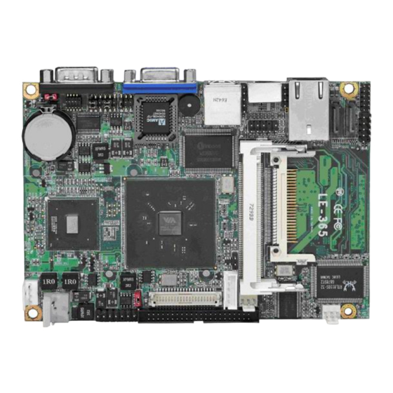
Introduction Chapter 1 <Introduction> 1.1 <Product Overview> LE-365 is the 3.5 inches embedded miniboard based on VIA CX700M platform, with onboard VIA Eden 1G processor, VGA, LAN, Audio, USB2.0, CF, LVDS. The board provides economic fanless solution for multimedia applications. -
Page 8: Product Specification
LE-365 User’s Manual Introduction 1.2 <Product Specification> General Specification Form Factor 3.5 inches embedded miniboard Embedded VIA V4 Eden 1G processor Front side bus: 400MHz Fanless with heatsink only Memory 1 x 200-pin DDR2 400/533 SO-DIMM SDRAM up to 1GB... - Page 9 LE-365 User’s Manual Introduction Panel voltage 3.3V/5V jumper selectable Ethernet Interface Chipset Realtek RTL8110S-32 Gigabit Ethernet controller Type 10/100/1000 Base-TX auto-switching Fast Ethernet Full duplex, IEEE802.3U compliant Connector External RJ45 connectors with LED on rear I/O panel Audio Interface Chipset...
-
Page 10: Mechanical Drawing
LE-365 User’s Manual Introduction 1.3 <Mechanical Drawing> Mechanical Drawing... -
Page 11: Block Diagram
LE-365 User’s Manual Introduction 1.4 <Block Diagram> Eden nanoBGA2 1 x 200-pin SO-DIMM DDR2 400/533MHz CRT/LCD Monitor up to 1GB CX700M LVDS or DVI VT 1708A 2 x SATA 4 x USB2.0 ports CompactFlash&IDE BIOS ICH7-M 83697HG RTL8110S-32 2 x Serial ports... -
Page 12: Chapter 2
LE-365 User’s Manual Hardware Setup Chapter 2 <Hardware Setup> 2.1 <Connector Location> (1)LE-365X CN_LVDS CPUFAN SYSFAN DC_IN JFRNT DC_OUT CN_INV MINIPCI2 CN AUDIO CN_USB2 CN_DIO CD_IN SATA1/2 CN_IR CN_COM2 (2)LE-365D CN_DVI CPUFAN SYSFAN DC_IN JFRNT DC_OUT MINIPCI2 CN AUDIO CN_USB2... - Page 13 LE-365 User’s Manual Hardware Setup DDRII MINIPCI1 RJ45 COM1 Connector Location...
-
Page 14: Jumper Reference
LE-365 User’s Manual Hardware Setup 2.2 <Jumper Reference> Jumper Function JRTC CMOS Operating/Clear Setting JVLCD LCD Panel Voltage Setting AT Mode JCSEL1/2 COM2 RS232/422/485 mode setting JVLCD JRTC JCSEL1 JCSEL2 Jumper Reference... -
Page 15: Connector Reference
LE-365 User’s Manual Hardware Setup 2.3 <Connector Reference> 2.3.1 <Internal Connector> Connector Function Remark DDRII 200 -pin DDR2 SO-DIMM SDRAM slot SATA1/2 7-pin Serial ATA connector CN_AUDIO 5 x 2-pin audio connector CD_IN 4-pin CD-ROM audio input connector CN_DIO 6 x 2-pin digital I/O connector... -
Page 16: Cpu And Memory Setup
LE-365 User’s Manual Hardware Setup 2.4 <CPU and Memory Setup> 2.4.1< CPU> The board comes with the VIA V4 Eden 1GHz processor , it supports new generation of VIA V4 Eden 1GHz processor with 400MHz of front side bus and 2MB L2 cache. Please follow the instruction to install the CPU properly. -
Page 17: Cmos Atx Setup
LE-365 User’s Manual Hardware Setup 2.5 <CMOS ATX Setup> The board’s data of CMOS can be setting in BIOS. If the board refuses to boot due to inappropriate CMOS settings, here is how to proceed to clear (reset) the CMOS to its default values. -
Page 18: Enhanced Ide & Cf Interface
LE-365 User’s Manual Hardware Setup 2.6 <Enhanced IDE & CF interface> The board supports one UltraDMA133 IDE interface, and one CompactFlash Type II socket with secondary IDE mode, the 44-pin IDE connector can support up to 2 ATAPI devices through IDE cable, and the CompactFlash socket can support IDE DMA mode (depends on the CF card specification). -
Page 19: Serial Ata Interface
LE-365 User’s Manual Hardware Setup 2.7 <Serial ATA Interface> Based on VIA CX700M, the board provides two Serial ATA interfaces with up to 300MB/s of transfer rate SATA1/2 2.8 <LAN Interface> The Realtek RTL8110S-32 supports triple speed of 10/100/1000Base-T, with IEEE802.3 compliance and Wake-On-LAN supported. -
Page 20: Analog Vga Interface
LE-365 User’s Manual Hardware Setup 2.9 <Onboard Display Interface> Based on VIA CX700M chipset with built-in GMA (Graphic Media Accelerator) 950 graphics, the board provides one DB15 connector on real external I/O port, and one 40-pin LVDS interface with 5-pin LCD backlight inverter connector. The board provides dual display function with clone mode and extended desktop mode for CRT and LCD or DVI . -
Page 21: Digital Display
LE-365 User’s Manual Hardware Setup 2.9.2 <Digital Display> The board provides one 40-pin LVDS connector for 18/24-bit dual channel panels, supports up to 1600 x 1200 (UXGA) of resolution, with one LCD backlight inverter connector and one jumper for panel voltage setting.(LE-365X Only)... - Page 22 LE-365 User’s Manual Hardware Setup Connector: CN_INV Connector: JVLCD Type: 5-pin LVDS Power Header Type: 3-pin Power select Header Connector model: JST B5B-XH-A Description Description +12V VCC(5V) LCDVCC VCC(3.3V) ENABKL Connector: CN_LVDS Type: onboard 40-pin connector for LVDS connector Connector model: HIROSE DF13-40DP-1.25V...
- Page 23 LE-365 User’s Manual Hardware Setup To setup the LCD, you need the component below: A panel with LVDS interfaces. An inverter for panel’s backlight power. A LCD cable and an inverter cable. For the cables, please follow the pin assignment of the connector to make a cable, because every panel has its own pin assignment, so we do not provide a standard cable;...
- Page 24 LE-365 User’s Manual Hardware Setup After setup the devices well, you need to select the LCD panel type in the BIOS. The panel type mapping is list below: LE-365 BIOS panel type selection form Resolution Color Channel 640 x 480...
-
Page 25: Dvi Interface
LE-365 User’s Manual Hardware Setup 2.9.3 <DVI Interface > The board also comes with a DVI interface with VIA CX700M for digital video interface. Connector: CN_DVI(LE-365D Only) Connector type: 26-pin header connector (pitch = 2.54mm) Pin Number Assignment Pin Number... -
Page 26: Onboard Audio Interface
LE-365 User’s Manual Hardware Setup 2.10 <Onboard Audio Interface> T The board provides the onboard HD audio interface with VIA VT1708A Connector: CN_AUDIO Type: 10-pin (2 x 5) header (pitch = 2.54mm) Description Description MIC_L Ground MIC_R ACZ_DET Speaker_R MIC Detect... -
Page 27: Usb2.0 Interface
LE-365 User’s Manual Hardware Setup 2.11 <USB2.0 Interface> Based on VIA CX700M , the board provides 4 USB2.0 ports. The USB2.0 interface provides up to 480Mbps of transferring rate. Interface USB2.0 Controller CX700M Transfer Rate Up to 480Mb/s Output Current... - Page 28 LE-365 User’s Manual Hardware Setup Connector: CN_IR Type: 5-pin header for SIR Port Description IRRX Ground IRTX Connector: CN_USB Type: 10-pin (5 x 2) header for USB Port Description Description Data0- Data1- Data0+ Data1+ Ground Ground Ground PS: The USB2.0 will be only active when you connecting with the USB2.0 devices, if you insert an USB1.1 device, the port will be changed to USB1.1 protocol automatically.
-
Page 29: Gpio Interface
LE-365 User’s Manual Hardware Setup 2.12 <GPIO Interface> The board provides a programmable 8-bit digital I/O interface; you can use this general purpose I/O port for system control like POS or KIOSK. Connector: CN_DIO Type: onboard 2 x 6-pin header, pitch=2.0mm... -
Page 30: Serial Port Jumper Setting
LE-365 User’s Manual Hardware Setup 2.13 <Serial Port Jumper Setting > The board provides two RS232 serial ports, with jumper selectable RS422/485 for COM2. Connector: CN_COM2 Type: 10-pin (5 x 2) 1.27mm x 2.54mm-pitch header for COM2 Description Description DCD/422RX-/485-... - Page 31 LE-365 User’s Manual Hardware Setup CN_COM2 JCSEL2 JCSE COM1 Serial Port Jumper Setting...
-
Page 32: Power Input
LE-365 User’s Manual Hardware Setup 2.14 <Power and Fan Connector> The board requires DC input with 3-pin hear, the i t vo ltage range is from 8V to 24V, for the input current, please take a reference of the po wer co nsumption report on appendix. -
Page 33: Power Output
LE-365 User’s Manual Hardware Setup 2.14.2 <Power Output> Connector: DC_OUT Type: 4-pin connector for +5V/+12V output Pin Description Pin Description Pin Description Pin Description +12V Ground Ground 2.14.3 <Fan Connector> Connector: SYSFAN, CPUFAN Type: 3-pin fan wafer connector Description Description... -
Page 34: Indicator And Switch
LE-365User’s Manual Hardware Setup 2.15 <Indicator and Switch> The JFRNT provides front control panel of the board, such as power button, reset and beeper, etc. Please check well before you connecting the cables on the chassis. Connector: JFRNT Type: onboard 14-pin (2 x 7) 2.54-pitch header Function Signal Signal... - Page 35 LE-365 User’s Manual (This Page is Left For Blank)
-
Page 36: Chapter 3
LE-365User’s Manual System Setup Chapter 3 <System Setup> 3.1 <Display Configuration> The board provides onboard VGA with DB15 analog display interface, and LVDS LCD interface for digital display, when connecting two display devices, you can enable dual display function with clone mode or extended desktop mode. Before setup the video setting, please install the VGA driver well. - Page 37 LE-365 User’s Manual System Setup Please select S3Display for advanced device setting. Specified display setup if available When you set dual display clone mode, you’ll see the same screen display on two devices. When you set the dual display for extended desktop mode, you can have the independent desktop on the second device.
- Page 38 LE-365 User’s Manual (This Page is Left for Blank)
-
Page 39: Chapter 4
LE-365 User’s Manual BIOS Setup Chapter 4 <BIOS Setup> The motherboard uses the Award BIOS for the system configuration. The Award BIOS in the single board computer is a customized version of the industrial standard BIOS for IBM PC AT-compatible computers. It supports Intel x86 and compatible CPU architecture based processors and computers. - Page 40 LE-365 User’s Manual (This Page is Left for Blank)
-
Page 41: Appendix A
LE-365 User’s Manual I/O Port Pin Assignment Appendix A <I/O Port Pin Assignment> A.1 <IrDA Port> Connector: CN_IR Type: 5-pin header for SIR Port Description IRRX Ground IRTX A.2 < CRT Port > Connector: CRT Type: 15-pin D-sub female connector on panel... -
Page 42: Serial Port
LE-365 User’s Manual I/O Port Pin Assignment A.4 <Serial Port> Connector: COM1 Type: 9-pin D-sub male connector on rear panel Description Description Ground A.5 <LAN Port> Connector: RJ45 Type: RJ45 connector with LED on rear panel Description Serial Port... -
Page 43: Appendix B
LE-365 User’s Manual Flash BIOS Appendix B <Flash BIOS> B.1 BIOS Auto Flash Tool The board is based on Award BIOS and can be updated easily by the BIOS auto flash tool. You can download the tool online at the address below: http://www.award.com... -
Page 44: Appendix C
LE-365 User’s Manual Flash BIOS Appendix C <System Resources> C1.<I/O Port Address Map> Memory Address Map... - Page 45 LE-365 User’s Manual System Resources I/O Port Address Map...
- Page 46 LE-365 User’s Manual System Resources C2.<Memory Address Map> I/O Port Address Map...
- Page 47 LE-365 User’s Manual System Resources C3.<System IRQ Resources> System IRQ Resources...
- Page 48 LE-365 User’s Manual (This Page is Left for Blank)
-
Page 49: Contact Information
Taiwan Commate Computer Inc. Address 8F, No. 94, Sec. 1, Shin Tai Wu Rd., Shi Chih Taipei Hsien, Taiwan +886-2-26963909 +886-2-26963911 Website http://www.commell.com.tw E-Mail info@commell.com.tw (General Information) tech@commell.com.tw (Technical Support) Commell is our trademark of industrial PC division Contact Information...
Need help?
Do you have a question about the LE-365 and is the answer not in the manual?
Questions and answers