Table of Contents
Advertisement
Quick Links
Advertisement
Table of Contents

Subscribe to Our Youtube Channel
Related Manuals for Riken Keiki TP-70DGII


Summary of Contents for Riken Keiki TP-70DGII
- Page 1 PT5E-0581 Gas Detector TP-70DGII Operating Manual...
-
Page 2: Table Of Contents
Contents 1. Outline of the Product ............................. 2 1-1. Preface ..............................2 1-2. Purpose of use ............................2 1-3. Definition of DANGER, WARNING, CAUTION and NOTE ..............2 1-4. Method of confirmation for CE marking type ..................3 2. Important Notices on Safety ........................... 4 2-1. -
Page 3: Outline Of The Product
Outline of the Product 1-1. Preface Thank you for choosing our gas detector TP-70DGII. Please check that the model number of the product you purchased is included in the specifications on this manual. Non-compliance with safety precautions in use of electrical products may lead to fire or bodily injury. -
Page 4: Method Of Confirmation For Ce Marking Type
1. Outline of the Product 1-4. Method of confirmation for CE marking type 1-4. Method of confirmation for CE marking type The CE marking is labeled on the detector in case of comply with CE marking. Please confirm the instrument specification before using. Please refer Declaration of Conformity that is at the end of this manual if you have CE marking type. -
Page 5: Important Notices On Safety
2. Important Notices on Safety 2-1. Danger cases Important Notices on Safety 2-1. Danger cases DANGER This is not an explosion-proof unit. Do not use the unit in place where combustible gases may exist. 2-2. Warning cases WARNING Power supply Before turning on the gas detector, always check that the voltage is properly applied. - Page 6 2. Important Notices on Safety 2-2. Warning cases WARNING Handling the sensor unit Do not disassemble the electrochemical type sensor unit (ESU) because it contains electrolyte. Electrolyte may cause severe skin burns if it contacts skin, while it may cause blindness if it contacts eyes.
-
Page 7: Precautions
A filter to be used varies depending on the gas to be detected. For more information on filters, please contact RIKEN KEIKI. Also, the gas detector itself is not dust-proof. Take an appropriate measure such as attaching a protective cover when the gas detector is used in a dusty environment. -
Page 8: Product Components
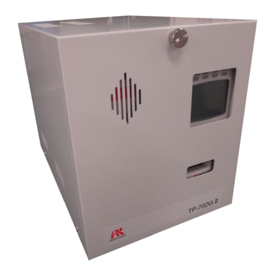
3. Product Components 3-1. Main unit and standard accessories Product Components 3-1. Main unit and standard accessories <Main Unit> <Standard Accessories> Operating Manual Protective rubber cap (to be removed when using the gas detector) Dust filter Silica gel filter (when using the gas detector for C4F6/C5F8 detection) - 7 -... -
Page 9: Outline Drawing
3. Product Components 3-2. Outline drawing 3-2. Outline drawing 3-3. Names and functions for each part <Components of the Gas Detector> Caution high temperature The gas detector consists of the following units. Display unit Sensor unit CAUTION Each unit consists of precision parts. When a unit is detached, be careful not to drop it. Dropping the unit compromises its original performance or causes malfunctions. - Page 10 3. Product Components 3-3. Names and functions for each part <Exterior of Main Unit> (10) Display Display the gas concentration and so on. Sensor unit nameplate The sensor unit nameplate can be checked from this window. display window You can identify the currently attached sensor unit. Knurled screw Fix the front cover.
- Page 11 3. Product Components 3-3. Names and functions for each part <Interior of Main Unit> <Unit Panels and Character LCD> (1) MODE key (7) First alarm lamp Display unit (8) Second alarm lamp Pyrolyzer (2) TEST/SET key (3) ▲ key (9) Fault lamp (6) Power lamp (4) ▼...
- Page 12 3. Product Components 3-3. Names and functions for each part <Detaching and Attaching Sensor Unit> Loosen the knurled screw that fixes the front cover of the main unit and open the cover. Knurled screw Top view Push the two buttons at the top of the display unit together to open the front cover.
- Page 13 3. Product Components 3-3. Names and functions for each part <Detaching and Attaching Pump Unit> Open the front cover of the main unit. Slide the tab in the direction of the arrow (toward the inside of the main unit) to open/close the pump unit cover.
-
Page 14: Block Diagram
Although warm-up time is different depending on the type of the installed sensor, it is recommended that warm-up should be performed for three hours or more. Please contact RIKEN KEIKI for more information. The sensor unit must be stored in a clean, cool and dark place away from direct sunlight. - Page 15 3. Product Components 3-4. Block diagram <Electric Diagram> Sensor unit Power supply part Amplifier POWER INPUT (24 VDC) Controller Alarm contact controller (CPU) Controller Gas alarm contact (ALM1, (CPU) ALM2) Fault alarm contact (FAULT) * Standard setting of contact activation Display ・...
-
Page 16: How To Use
4. How to Use 4-1. Before using the gas detector How to Use 4-1. Before using the gas detector Not only the first-time users but also the users who have already used the gas detector never fail to follow the operating precautions. Ignoring the precautions may damage the gas detector, resulting in inaccurate gas detection. - Page 17 4. How to Use 4-2. Precautions for installation sites Do not install the gas detector in a place exposed to water, oil or chemicals. When selecting installation points, avoid a place where the gas detector is exposed to water, oil or chemicals. Do not install the gas detector in a place where the temperature drops below 20ºC or rises over 40ºC.
-
Page 18: Precautions For System Designing
4. How to Use 4-3. Precautions for system designing 4-3. Precautions for system designing CAUTION An unstable power supply and noise may cause malfunctions or false alarms. The descriptions in this section must be reflected on the designing of a system using the gas detector. - Page 19 4. How to Use 4-3. Precautions for system designing * The lightning arrester has a circuit to remove a surge voltage which damages field devices, so that signals may be attenuated by installing the arrester. Before installing a lightning arrester, verify that it works properly.
-
Page 20: How To Wire
4. How to Use 4-4. How to wire TP-70DGII Coil Load Power Power supply supply Alarm contact External relay (low voltage relay) * SK1, SK2: Surge absorbing parts 4-4. How to wire CAUTION Be careful not to damage the internal electronic circuit when wiring. In addition, be careful not to apply stresses on the gas detector when (overweight) cables are installed. - Page 21 4. How to Use 4-4. How to wire NOTE The 24 VDC terminals 1 and 2 are unavailable for the Ethernet and PoE specifications. (Connection prohibited) The 4 - 20 mA terminals 3 and 4 are unavailable for the 2-wire type DC power-line communication system (NT) specification.
- Page 22 4. How to Use 4-4. How to wire <Wiring Example> Connecting to the upper unit (DCS, PLC) (EA specification, 2-wire type/4 - 20 mA) Upper unit (DCS, PLC) Power supply (100 - 240 VAC) Connecting to the upper unit (PC, PLC) (EA specification with Ethernet) RJ45 connector Upper unit (PC, PLC)
- Page 23 4. How to Use 4-4. How to wire Connecting to the upper unit (PC, PLC) (EA specification with PoE) RJ45 connector Upper unit (PC, PLC) Switching Power supply (with PoE (100 - 240 VAC) function) CAUTION Be sure to use a switching hub equipped with PoE function with the PoE specification. If the PoE function is unavailable, the power will not be supplied to the display unit.
-
Page 24: How To Tube
Determine the inlet for the sample gas, considering the airflow of the sample gas line and the gas generating process. Never fail to attach the supplied filter in the middle of the tube. It is needed to decide the length and material of the tube. Please contact RIKEN KEIKI for more information. - 23 -... -
Page 25: How To Operate
5. How to Operate 5-1. Preparation for start-up How to Operate 5-1. Preparation for start-up Before connecting a power supply, read and understand the following precautions. Ignoring these precautions may cause an electric shock or damage the unit. Connect the gas detector to a grounding circuit. ... -
Page 26: Basic Operating Procedures
5. How to Operate 5-2. Basic operating procedures 5-2. Basic operating procedures Normally, the detection mode is used for normal operations. (The detection mode is activated after the power is turned on.) PW: POWER ●: Lamp on A1: ALM1 ○: Lamp off <Detection Mode>... - Page 27 5. How to Operate 5-3. How to activate the gas detector <PoE Specification> For the PoE specification, the power is supplied via a LAN cable, and the power switch of the display unit needs to be operated. The power switch of the display unit is protected by a cover to prevent access to it in a normal time. To turn ON/OFF the power switch, rotate the switch cover.
- Page 28 5. How to Operate 5-3. How to activate the gas detector <Start-up Procedures (approximately 25 seconds for system check of the gas detector and alarm deactivation)> Power On ↓ ● ○ ○ ○ Initial clear ---- WARM UP ↓ ↓ ●...
-
Page 29: Modes
5. How to Operate 5-4. Modes 5-4. Modes Details on each mode are provided as follows. (* Operations are slightly different depending on the sensor unit.) Mode Item LCD display Details Detection Gas concentration Normal state - mode Gas name Alarm Gas concentration Perform the alarm test. -
Page 30: Detection Mode
5. How to Operate 5-5. Detection mode 5-5. Detection mode <Flow Rate Indicator> Because the flow rate of the gas detector is automatically adjusted by the flow rate control function, the flow rate, in principal, does not need to be controlled. As shown on the figure below, when the flow rate does not correspond to the specified flow rate for some reasons, it is adjusted automatically. -
Page 31: Alarm Test Mode
5. How to Operate 5-6. Alarm test mode 5-6. Alarm test mode This is used when dummy signals the same as the signals of the gas concentration are generated to check the alarm lamp activation of the gas detector and the transmission to external circuits. WARNING Before starting the alarm test (transmission test), provide a notification to the related sections so that they can prepare for false abnormalities (external output signals and alarm contact). -
Page 32: User Mode
5. How to Operate 5-7. User mode 5-7. User mode WARNING After the adjustment is completed, never fail to press the MODE key to return to the detection mode. (If the gas detector remains in the user mode, it automatically returns to the detection mode in ten hours.) ●... - Page 33 5. How to Operate 5-7. User mode ↓↑ ▲ ▼ ● ○ ○ ○ → 1-7. NET VER 1- 7 01234 the program Display NET VER ---- version of the communication MAINTENANCE MAINTENANCE function. ↓↑ ▲ ▼ ● ○ ○ ○...
- Page 34 5. How to Operate 5-7. User mode <Zero Adjustment "1-1"> This is used to perform the zero adjustment. Before starting the zero adjustment, let the gas detector draw the zero adjustment gas and wait until the reading is stabilized. ● ○...
- Page 35 5. How to Operate 5-7. User mode <Setting Display "1-2"> This is used to check the setting of typical menus. ● ○ ○ ○ 1-2. CONFIRM 1- 2 Press SET key. CONFIRM MAINTENANCE ↓ ↓ ● ○ ○ ○ First Alarm Setpoint 5.0 ppm Display AL 1...
-
Page 36: How To Exit
5. How to Operate 5-8. How to exit 5-8. How to exit To turn off the gas detector, turn "OFF" the power switch located on the rear side of the main unit. Then, turn off the power supply to the gas detector. WARNING ... -
Page 37: Operations And Functions
6. Operations and Functions 6-1. Gas alarm activation Operations and Functions 6-1. Gas alarm activation Gas alarm: Triggered when the concentration of detected gas reaches or exceeds the alarm setpoint value. <Auto-Reset Operation> NOTE The alarm setpoint (first alarm and second alarm) is factory-set. Although the alarm delay time (standard: two seconds) works in the gas detector to prevent a false activation, it can be canceled if not needed. - Page 38 6. Operations and Functions 6-1. Gas alarm activation <Contact Activation> The contact is activated when the gas concentration reaches or exceeds the alarm setpoint value. The contact activation is reset automatically when the gas concentration drops below the alarm setpoint value. "Alarm Pattern (H-HH)"...
-
Page 39: Fault Alarm Activation
After the gas detector is successfully returned from the fault, it restarts with the process normally performed right after it is turned on (initial clear). If the gas detector has problems and is repeatedly malfunctioning, contact RIKEN KEIKI immediately. * E-5 FLOW... -
Page 40: External Output Operation
6. Operations and Functions 6-3. External output operation 6-3. External output operation Specifications 4 - 20 mA Power-line Ethernet communication system Signal Transmission Analog transmission (non-isolated) 2-wire type DC Ethernet System power-line (10BASE-T/100BASE- communication Transmission Path CVVS KPEV-S Ethernet cable Transmission Below 1 km Below 300m... - Page 41 6. Operations and Functions 6-3. External output operation Example of Gas Concentration and External Output External output 4 - 20 mA (Maintenance output: 22mA 2.5 mA setting) 20mA Detection mode Maintenance mode 2.5 mA Zero suppression Gas concentration Full scale CAUTION <Analog Transmission (4 - 20 mA)>...
-
Page 42: Other Functions
6. Operations and Functions 6-4. Other functions 6-4. Other functions <Suppression Function> Some types of sensor used with the gas detector are influenced by environmental changes (temperature, humidity, and other characteristics) or interference gases (interference characteristics) in no small measure, which affects the reading. - Page 43 6. Operations and Functions 6-4. Other functions <Zero Follower Function> Some types of sensor used with the gas detector might have sensitivity variations after being used for a long period. This function corrects the variation of the reading at the zero point (zero drift) among the sensitivity variations over time by a program manipulation to stabilize the zero point, and works on the electrochemical type (ESU) and pyrolysis-particle type (SSU).
- Page 44 <Calibration History/Alarm Trend History/Event History Functions> The gas detector and the sensor unit have their own history functions. To use these functions, please contact RIKEN KEIKI. <Sensor Unit Automatic Recognition Function> The gas detector has the function to automatically recognize the sensor unit when the sensor unit is replaced or the specification is changed.
-
Page 45: Maintenance
Our qualified service engineers have expertise, knowledge and other information on the dedicated tools used for services, along with other products. To maintain the safety operation of the gas detector, please use our maintenance service. Typical maintenance services are listed as follows. Please contact RIKEN KEIKI for more information. - 44 -... - Page 46 7. Maintenance 7-1. Maintenance intervals and items Main services Power supply Checks the power supply voltage. check Verifies that the power lamp lights up. (Verifies that relevant points can be identified on the system.) (When a UPS (uninterruptible power system) is used, checks the operation with the UPS.) Concentration Verifies that the concentration display value is zero by using the zero gas.
-
Page 47: Regular Maintenance Mode
7. Maintenance 7-2. Regular maintenance mode 7-2. Regular maintenance mode WARNING After the adjustment is completed, never fail to press the MODE key to return to the detection mode. (If the gas detector remains in the regular maintenance mode, it automatically returns to the detection mode in ten hours.) Mode Item... - Page 48 7. Maintenance 7-2. Regular maintenance mode Mode Item LCD display Details Pyrolyzer data 2-11 PL DATA Display various pyrolyzer data. display => P62 Fault investigation 2-12 FAULT Not used. Catalyst aging 2-13 PL Perform aging of catalyst. function AGING => P64 Factory mode 2-14 F MODE Not used.
- Page 49 7. Maintenance 7-2. Regular maintenance mode PW: POWER ●: Lamp on ● ○ ○ ○ User Mode 1- 8 A1: ALM1 ○: Lamp off In "1-8. M MODE", A2: ALM2 M MODE press the SET key. F: FAULT MAINTENANCE ↓ ↓...
- Page 50 7. Maintenance 7-2. Regular maintenance mode ↓↑ ▲ ▼ ● ○ ○ ○ 2-5. DEF FLOW 2- 5 1000 ⇔ This is not used on the DEF FLOW DEF FLOW gas detector. MAINTENANCE MAINTENANCE || ▲ ▼ ● ○ ○ ○...
- Page 51 7. Maintenance 7-2. Regular maintenance mode ↓↑ ▲ ▼ ● ○ ○ ○ 2-12. FAULT 2-12 This is used (by the FAULT manufacturer) to investigate and analyze MAINTENANCE the causes of faults. ↓↑ This is not used by the user. ↓↑...
- Page 52 7. Maintenance 7-2. Regular maintenance mode <Environmental Setting 1 "2-9"> In the environmental setting 1, specify the operation setting. <Environmental Setting 1> ● ○ ○ ○ 2- 9 2-9. SETTING1 Press SET key. SETTING1 MAINTENANCE ↓ ↓ ● ○ ○ ○...
- Page 53 7. Maintenance 7-2. Regular maintenance mode <Alarm Value Setting "2-9" - "SET 1"> PW A1 A2 ● ○ ○ ○ SET 1 SET 1. ALM P Press SET key. ALM P MAINTENANCE ↓ ↓ ● ○ ○ ○ First alarm value setting 5.0ppm Change the value by pressing the ▲...
- Page 54 7. Maintenance 7-2. Regular maintenance mode <Environmental Setting 2 "2-10"> In the environmental setting 2, specify the settings of functions. (* It is recommended that setting changes should be recorded in a log.) The environmental setting 2 includes setting menus which are usually not used. Be careful not to change these settings by mistake.
- Page 55 7. Maintenance 7-2. Regular maintenance mode ↓↑ ▲ ▼ ● ○ ○ ○ SET 4. TEST RLY SET 4 ⇔ Set the contact TEST RLY TEST RLY activation for an alarm test. MAINTENANCE MAINTENANCE Select either ON/OFF, ▲↓↑▼ |↑ and then press the SET key to confirm the selection.
- Page 56 7. Maintenance 7-2. Regular maintenance mode ↓↑ ▲ ▼ ● ○ ○ ○ SET 8. ALM PTRN SET 8 This is a setting screen ALM PTRN of the gas alarm pattern. Do not change MAINTENANCE the setting when the |↑ gas detector is used in a normal way, because it determines how the...
- Page 57 7. Maintenance 7-2. Regular maintenance mode ↓↑ ▲ ▼ ● ○ ○ ○ SET 13. ZERO 24F SET 13 This is a supplemental ZERO 24F setting screen for the above zero follower MAINTENANCE function. (A setting to |↑ determine whether the first-24-hour zero follower will be ||...
- Page 58 7. Maintenance 7-2. Regular maintenance mode ↓↑ ▲ ▼ ● ○ ○ ○ SET 16. MA 4-20 SET 16 100% ⇔ Adjust the external MA 4-20 4MA ADJ output (4 - 20 mA). Adjust the output (%) by MAINTENANCE MAINTENANCE pressing the ▲...
- Page 59 7. Maintenance 7-2. Regular maintenance mode <Date/Time Setting "2-10" - "SET 1"> ● ○ ○ ○ SET 1 SET 1. DAY TIME Press SET key. DAY TIME MAINTENANCE ↓ ↓ ● ○ ○ ○ Date/time setting display 12:00 Press SET key. 2009.01.01 MAINTENANCE ↓...
- Page 60 7. Maintenance 7-2. Regular maintenance mode <Energized/De-energized Setting “2-10” - ”SET 6”> ● ○ ○ ○ SET 6 SET 6. RLY PTRN Press SET key. RLY PTRN MAINTENANCE ↓ ↓ ● ○ ○ ○ First Alarm Contact ⇔ Setting ▲/▼ AL1 RLY AL1 RLY Select either nd...
- Page 61 7. Maintenance 7-2. Regular maintenance mode <ETHERNET Setting "2-10" - "SET 18"> ● ○ ○ ○ SET 18 SET 18. ETHERNET Press SET key. ETHERNET MAINTENANCE ↓ ↓ ● ○ ○ ○ MAC Address Check There are MAC MAC 1 addresses from MAC1 to MAC6.
- Page 62 7. Maintenance 7-2. Regular maintenance mode ↓↑ ▲ ▼ ● ○ ○ ○ Default Gateway ⇔ Setting DEF 1 DEF 1 Change the value by pressing the ▲ or ▼ MAINTENANCE MAINTENANCE key, and then press ↓↑ the SET key to ▲...
- Page 63 7. Maintenance 7-2. Regular maintenance mode <Pyrolyzer Heater Data Display "2-11"> ● ○ ○ ○ 2-11 2-11. PL DATA Press SET key. PL DATA MAINTENANCE ↓ ↓ ● ○ ○ ○ PL-0 .PL H.TEMP PL-0 ⇔ 120ºC Display the pyrolyzer PL H.TEMP heater temperature.
- Page 64 7. Maintenance 7-2. Regular maintenance mode ↓↑ ▲ ▼ ● ○ ○ ○ PL-6 .PL 3.3V PL-6 3300 mv ⇔ Display the pyrolyzer PL 3.3V PL 3.3V 3.3 V output. MAINTENANCE MAINTENANCE ↓↑ ▲ ▼ ● ○ ○ ○ PL-7 .PL 5.0V PL-7 5000 mv ⇔...
- Page 65 7. Maintenance 7-2. Regular maintenance mode <Catalyst Aging Function “2-13”> ● ○ ○ ○ 2-13 2-13.PL AGING Press SET key. PL AGING MAINTENANCE ↓ ↓↑ ▲ ▼ Then press the SET key ● ○ ○ ○ again for three seconds. PL AGING MAINTENANCE ↓...
-
Page 66: Calibration Method
7. Maintenance 7-3. Calibration method 7-3. Calibration method Perform a calibration in each mode (zero adjustment mode and span adjustment mode) using the calibration gas. Zero adjustment gas (collected in a gas sampling bag) Calibration gas (collected in a gas sampling bag) ... - Page 67 7. Maintenance 7-3. Calibration method * When the zero adjustment fails ● ○ ○ ○ 0.0 ppm ZERO NG MAINTENANCE ↓ Return to 2-1. ZERO <Span Adjustment "2-2"> This is used to perform the span adjustment. PW A1 A2 F ●...
- Page 68 7. Maintenance 7-3. Calibration method ↓ ● ○ ○ ○ Adjustment Completed 8.0 ppm The menu returns to 2-2. SPAN SPAN END automatically. MAINTENANCE CAUTION | Exhaust gas must be collected in | the exhaust bag or discharged through the exhaust line. ↓...
-
Page 69: Other Adjustments/Cleaning Method
7. Maintenance 7-4. Other adjustments/cleaning method 7-4. Other adjustments/cleaning method <Flow Rate Manual Adjustment “2-6”> The flow rate of the gas detector is automatically adjusted to 0.5 L/min. Turning off the auto-adjustment function enables the manual adjustment. (See “2-10” - “SET 11”) The manual flow rate adjustment can be performed in the regular maintenance mode "2-6. -
Page 70: How To Replace Parts
7. Maintenance 7-5. How to replace parts 7-5. How to replace parts <Replacement of Consumables> External Dust Filter Replacement Because the external dust filter may gradually get dirty or clogged over the time, it must be replaced regarding the operating conditions. Check the external dust filter, and then replace it as necessary. - Page 71 After the flow sensor, fan or catalyst tube is replaced, the operation must be checked by a qualified service engineer. Since the catalyst tube has an influence over gas sensitivity, calibration needs to be performed after replacement. Please contact RIKEN KEIKI. Sensor Unit Replacement For the replacement of sensor unit, see "Detaching and Attaching Sensor Unit"...
-
Page 72: Storage, Relocation And Disposal
For information on wiring and tubing, see "4-4. How to wire" and "4-5. How to Tube". The unpowered time must be minimized when the gas detector is relocated. CAUTION When using a relocated or stopped/stored detector again, never fail to perform a calibration. For information on readjustment including calibration, please contact RIKEN KEIKI. - 71 -... -
Page 73: Disposal Of Products
If liquid is leaked from the electrochemical type sensor unit (ESU), do not touch the liquid. The sensor unit must be put into a plastic bag to prevent leaking. If liquid is leaked from the sensor of the gas detector, turn "OFF" the power and contact RIKEN KEIKI immediately. -
Page 74: Troubleshooting
This simply helps to find the causes of malfunctions which frequently occur. If the gas detector shows a symptom which is not explained in this manual, or still has malfunctions even though remedial actions are taken, please contact RIKEN KEIKI. ●: Lamp on ○: Lamp off... - Page 75 9. Troubleshooting Symptom/Display FAULT Causes Actions Sensor unit ● The unit is not Check that the sensor unit is connected and the abnormalities connected or connectors of the unit are securely fastened. improperly E-1 SENSOR connected. Errors in Replace the sensor unit with a new one. communication with the unit Zero drift caused by...
- Page 76 If such a symptom is observed repeatedly, the built-in clock is seemingly malfunctioning. Thus, it must be replaced. Please contact RIKEN KEIKI. System ● The rated voltage is Check the power supply, and supply the rated...
- Page 77 For information on actions, such as removal filter, please contact RIKEN KEIKI. Slow leak A very small amount of the gas to be detected may be leaking (slow leak). Because ignoring it may cause dangers, take a remedial measure, i.e., taking actions...
-
Page 78: Product Specifications
10. Product Specifications 10-1. List of specifications Product Specifications 10-1. List of specifications <Product Specifications> Model TP-70DGⅡ Detection principle Catalyst + electrochemical type Gas to be detected C4F6/C5F8/COS Concentration display Character LCD (Digital and Bar Meter Display) Detection range C4F6: 0 - 5 ppm/C5F8: 0 - 5 ppm/COS: 0 - 15 ppm Detection method Pump suction type/pyrolysis type Flow rate... -
Page 79: List Of Accessories
10. Product Specifications 10-2. List of accessories Structure Tabletop type External dimensions Approx. 180 (W) x 225 (H) x 285 (D) mm (projection portions excluded) Weight Approx. 6.0 kg <Specifications by Communication> Model (NT specification) (EA specification) (EA (PoE) specification) Digital transmission: Ethernet (10BASE-T/100BASE-TX) Analog transmission: 3-wire type analog... -
Page 80: Detection Principle
10. Product Specifications 10-3. Detection principle 10-3. Detection principle A gas to be detected is passed through the pyrolyzer containing a catalyst to decompose it into a substance (HF or H2S) which has high reaction activity to the electrochemical type sensor. The concentration of the target gas can be detected by detecting a gas generated after decomposition with the electrochemical type sensor. - Page 81 10. Product Specifications 10-3. Detection principle Special precautions for this principle 1. The gas detector may be interfered by gases other than the gas to be detected, solvents, vapors, etc. Please note that the alarm may be triggered by interference. In addition, it may be fluctuated by environmental (temperature, humidity, etc.) changes in the installation site.
-
Page 82: Definition Of Terms
When the gas detector is used in a dusty environment, it is recommended that a dust filter should be attached to its outside. The filter is specified based on the gas to be detected. Please contact RIKEN KEIKI. vol% Gas concentration indicated in the unit of one-hundredth of the volume... - Page 83 11. Definition of Terms - 82 -...
Need help?
Do you have a question about the TP-70DGII and is the answer not in the manual?
Questions and answers