
Subscribe to Our Youtube Channel
Related Manuals for Riken Keiki SP-220 FUM


Summary of Contents for Riken Keiki SP-220 FUM
- Page 1 Portable Gas Leak Detector SP-220 Series SP-220(TYPE FUM) SP-220(TYPE SC) Operating Manual Part Number: 71-0408 Revision: P2 Released: 5/15/17...
-
Page 2: Table Of Contents
Contents 1. Outline of the Product ............................. 3 Preface ................................3 Purpose of use ..............................3 Definition of DANGER, WARNING, CAUTION and NOTE ................3 2. Important Notices on Safety ........................... 4 2-1. Danger cases............................4 2-2. Warning cases ............................5 2-3. -
Page 3: Outline Of The Product
Outline of the Product Preface Thank you for choosing our gas leak detector SP-220 series (hereinafter referred to as the detector). Please check that the model number of the product you purchased is included in the specifications on this manual. This manual explains how to use the gas detector and its specifications. -
Page 4: Important Notices On Safety
Important Notices on Safety To maintain the performance and use the gas detector safely, observe the following instructions of DANGER, WARNING, and CAUTION. 2-1. Danger cases DANGER About use • This is not an explosion-proof detector. You must not use it to detect gases exceeding the lower explosive limit (LEL). -
Page 5: Warning Cases
2-2. Warning cases WARNING Sampling point pressure • The concentration meter is designed to draw gases under the atmospheric pressure. If excessive pressure is applied to the gas inlet and outlet of the detector, measured gases may leak out from its inside and may cause dangerous conditions. Be sure that excessive pressure is not applied to the detector’s gas inlet or outlet while used. -
Page 6: Precautions
2-3. Precautions CAUTION Do not expose the detector to oil, chemicals, etc. Do not submerge the detector under water. • Do not use in a place where the detector is exposed to liquids such as oil, chemicals, etc. • The detector is not water-pressure-resistant. Do not use the detector where a high water pressure is applied to it (under a faucet, shower, etc.) or submerge it under water for a long time. - Page 7 CAUTION Others • Exposing the sensor to a gas for a long time or a high-concentration gas may result in that the gas alarm will remain for a certain period. If the exposure occurs, allow the instrument to draw fresh air for more than 5 minutes (recommendation), and then perform air calibration again. •...
-
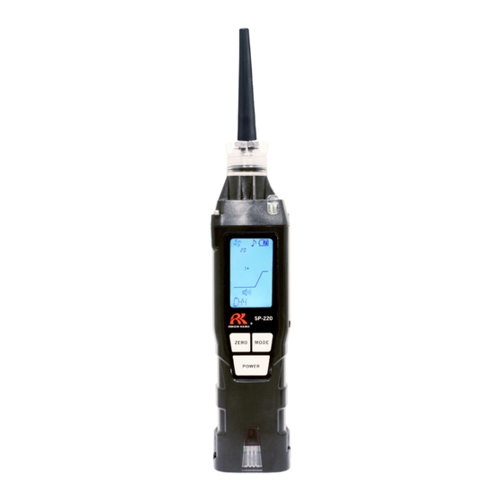
Page 8: Product Components
Product Components 3-1. Names and functions for each part This section describes names and functions of main unit and battery unit parts and LCD display. Main unit (11) (10) Name Function Gas inlet Collects gases. Alarm LED arrays Blinks or lights up in response to an alarm. LCD display Displays gas concentrations, measured gas name, alarms, etc. - Page 9 Standard accessories Unpack and check the main unit and accessories. • AA alkaline battery (2 pcs) (installed) • Taper nozzle (1 pc) • Rubber protection cover (1 pc) (Protect the detector from shocks by being hit, etc.) • Hand strap (1 pc) •...
- Page 10 LCD display Name Function Operating state display Displays the operating status in the detection mode. Normal: Blinking Flow check display Displays the flow rate status. Normal: Rotating Gas concentration Displays gas concentration and units (ppm). display Alarm sound display Displays the setting status of the alarm sound. Operation sound Displays the setting status of the operation sound.
-
Page 11: How To Use
How to Use 4-1. Before using the detector First-time users and users who have already used the detector must follow the operating precautions. Ignoring the precautions may damage the unit, resulting in inaccurate gas measurement. 4-2. Preparation for start-up Before use, read and understand the following precautions. Ignoring these may cause inaccurate gas detection. - Page 12 CAUTION • Never fail to turn off the power of the detector before replacing the batteries. • Replace the batteries in a safe place. • Replace both of the two batteries with new ones at one time. • Pay attention to the polarities during replacement. Replace while checking the battery polarities stamped on the body.
-
Page 13: How To Start The Detector
4-4. How to start the detector When the power is turned on, a self-diagnostic starts, and then the detector enters the detection mode. Power-on Press and hold the POWER button until the buzzer blips (one second or longer) to turn on the power. When the power is turned on, the LCD display changes automatically as shown below, and the detector enters the detection mode. - Page 14 * The date/time display is displayed only when the clock function is enabled. It is not normally displayed because the clock function is disabled by default. To enable the clock function, see "6-3. Clock function ON/OFF setting" on page 36. NOTE •...
-
Page 15: Basic Operating Procedures
4-5. Basic operating procedures The detection mode is used after power-on. Gas is detected in the ppm range. (Display example: For fumigation gases) AIR + POWER buttons MODE button Hold down for Hold down for Hold down for 1 sec 3 secs 3 secs Illumination... -
Page 16: How To Detect
4-6. How to detect While the detector is operating in detection mode, put the tip of the nozzle close to the detection area and draw sample. The detector measures gas in the ppm range. If a gas is drawn, the detected gas concentration is displayed with the bar meter on the LCD display. -
Page 17: Changing The Concentration Measuring Mode
4-7. Changing the concentration measuring mode In the detector, the detection gas type is factory set to PH3 (phosphine) and the alarm setpoint is factory set to 0.1 ppm. The alarm setpoint mode can be changed, depending on the gas to be detected, in three levels for fumigation gases and two levels for semiconductor material gases. - Page 18 Gas alarm setpoint for concentration measuring mode (for semiconductor material gases) 1 In the detection mode, press the AIR and MODE buttons at the same time. The alarm setpoint is changed to the next pre-defined setpoint every time the AIR and MODE buttons are pressed.
- Page 19 Change of gas alarm sensitivity for differential measuring mode (only for fumigation gases) 1 In the detection mode, press the AIR button. The alarm sensitivity changes from LOW MODE to HIGH MODE every time the AIR button is pressed. CAUTION •...
-
Page 20: Perform An Air Calibration
4-8. Perform an air calibration After a high-concentration gas is detected or an alarm is triggered by temperature/humidity changes, perform an air calibration in the measured atmosphere. * Before performing air calibration, verify a fresh air environment. (Display example: For fumigation gases) In the detection mode, hold down the AIR button. -
Page 21: Snap Logger
NOTE • Perform air calibration under pressure and temperature/humidity conditions close to those in the operating environment and in fresh air. • Perform an air calibration after the reading is stabilized. • If there is a sudden temperature change between the storage and operational locations, turn on the power of the detector, let it stand for ten minutes or more in a similar environment to the operational location, and perform air calibration in fresh air before using it. -
Page 22: Peak Hold Function
4-10. Peak hold function When the peak hold function is enabled, the latest peak value is always displayed with the bar meter. (Display example: For fumigation gases) In the detection mode, hold down the MODE button (for three seconds or longer). The peak hold function is enabled. -
Page 23: How To Turn On The Illumination Lamp
4-12. How to turn on the illumination lamp The illumination lamp can be turned on, if necessary. Hold down the AIR and POWER buttons at the same time (for three seconds or longer). The illumination lamp lights up. The illumination lamp will automatically go off two minutes after it lights up. -
Page 24: Display Mode
Display Mode 5-1. Entering the display mode This mode allows users to view and change various display settings. (Display example: For fumigation gases) In the detection mode, press the MODE button. The detector enters the peak value display in the display mode. - Page 25 Display mode overview Item LCD display Details Peak display Displays the maximum concentration detected during the period from power-on to the point of checking. * To clear the peak display, hold down the AIR button until "PEAK CLR" is displayed. (Display example: For fumigation gases) Concentration displayed...
- Page 26 Entering user mode Enters the user mode. (P. 33) Detection mode Returns to the detection mode. - 26 -...
-
Page 27: Concentration Displayed Gas Reading Setting
5-2. Concentration displayed gas reading setting Normally, the concentration display of the detector is "phosphine (PH3)" depending on the specification; however, a pre-registered gas can be read instead to detect its concentration. (Display example: For fumigation gases) On the "GAS LIST" screen in the display mode, press the POWER button. - Page 28 NOTE • To perform the concentration displayed gas reading setting, see the "Gas list" in the following page. Gas list for fumigation gases Gas name Display Scale 1 Scale 2 Scale 3 Remarks (standard name) Phosphine Methyl bromide CH3Br Sulfur compound. Carbon disulfide See the below NOTE.
- Page 29 Gas name Display Scale 1 Scale 2 Remarks (standard name) Chloride Methyl chloride CH3CL See the below NOTE. Xylene C8H10 Ethylene oxide Si compound Silane SiH4 See the below NOTE. Methyl bromide CH3Br Hydrogen Chloride Trichloroethylene C2HCL3 See the below NOTE. Toluene C7H8 Chloride...
- Page 30 NOTE • High-concentration or continuous contact with a chloride or sulfur compound will shorten the sensor life or cause larger errors. • If a Si compound is detected, the sensitivity will decrease. • Even for a gas shown only with the bar meter display but no scales, the meter reads Scale 2. Use it as an indication of concentration increase.
-
Page 31: Changing The Measuring Mode (Only For Fumigation Gases)
5-3. Changing the measuring mode (only for fumigation gases) The measuring mode of the detector (for fumigation gases) can be switched from "concentration measuring mode" to "differential measuring mode", where lower concentration detection can be conducted. On the "MODE CHG" screen in the display mode, press the POWER button. -
Page 32: Log Data Display
5-4. Log data display The data recorded by the snap logger can be viewed. The "REC DATA" screen is displayed only when the clock function is enabled (See "6-3. Clock function ON/OFF setting" on page 36). (Display example: For fumigation gases) On the "REC DATA"... -
Page 33: User Mode
User Mode 6-1. Entering the user mode The maintenance including internal clock correction, etc. can be performed. (Display example: For fumigation gases) In the detection mode, press the MODE button a few times to display entering user mode, press the POWER button The detector enters the date/time setting in the user mode. - Page 34 User mode overview Item LCD display Details Date/time setting Set the date/time of the internal clock. (P. 35) * When the clock function is disabled, the date/time setting screen is not displayed. Clock function ON/OFF Enable or disable the clock function. setting ROM/SUM display Displays the program number and SUM...
-
Page 35: Date/Time Setting
6-2. Date/time setting Set the date/time of the internal clock. The date/time setting screen is displayed only when the clock function is enabled. Enable the clock function in "6-3. Clock function ON/OFF setting" on page 36 before setting the date/time. On the "DATE"... -
Page 36: Clock Function On/Off Setting
6-3. Clock function ON/OFF setting Enable or disable the clock function. The clock function is disabled by default. If the date/time needs to be displayed on start-up or the snap logger function is used, enable the clock function. On the "CLOCK" screen in the user mode, press the POWER button. -
Page 37: Alarm Function
Alarm Function 7-1. Gas alarm activation When the concentration of detected gas reaches or exceeds the alarm setpoint values, a "gas alarm" is triggered in the detector. The alarm lamp blinks, the buzzer sounds, and the bar meter display indicates an alarm condition. -
Page 38: Maintenance
Maintenance The detector is a precision device. To maintain the performance of the detector and improve the reliability of detecting leakage , perform regular maintenance. 8-1. Maintenance intervals and items Perform the following maintenance regularly before use. • Daily maintenance: Perform maintenance before each day’s use. •... - Page 39 About maintenance services We provide services on regular maintenance including span adjustment, other adjustments and maintenance. To make the calibration gas, dedicated tools, such as a gas cylinder of the specified concentration, gas sampling bag, etc., must be used. Our qualified service engineers have expertise and knowledge on the dedicated tools used for services, along with other products.
-
Page 40: How To Clean
8-2. How to clean Clean the detector if it becomes extremely dirty. The detector must be turned off while cleaning it. Use a waste cloth or the like to remove dust. Do not use water or organic solvent for cleaning because they may cause malfunctions. - Page 41 Replace the hydrophobic filter with a new one. Make sure it’s seated in the rubber seal correctly. Hydrophobic Filter Rubber seal Attach the rubber seal, with the hydrophobic filter installed, to the cap. Make sure the rubber seal’s rib has been firmly inserted into the cap’s groove.
-
Page 42: Response Test
8-4. Response Test Even though the SP-220 cannot be calibrated in the field, a response test can be done to make sure the sensor is still responsive. This test is NOT meant to replace a calibration and is only meant to be used to determine general sensor functionality. -
Page 43: Storage And Disposal
Storage and Disposal 9-1. Procedures to store the detector or leave it for a long time The detector must be stored under the following environmental conditions. • In a dark place under the normal temperature and humidity away from direct sunlight •... - Page 44 <Disposal in EU Member States> When disposing of the detector in EU member states, sort the batteries as specified. Handle the removed batteries according to the classified refuse collection system and recycling system based on the regulations of EU member states. Removing batteries For battery removal, see "4-3.
-
Page 45: Troubleshooting
Troubleshooting This Troubleshooting section does not explain the causes of all the malfunctions which occur on the detector. This simply helps to find the causes of malfunctions which may frequently occur. If the gas detector shows a symptom which is not explained in this manual, or still has malfunctions even though remedial actions are taken, please contact RKI. - Page 46 Symptoms Causes Actions A low flow rate alarm is Water, oil or the like is Check the taper nozzle for any damage or displayed. drawn. mark of drawn water, oil, etc. FAIL LOW FLOW The taper nozzle is clogged. Check the taper nozzle for connection condition, clogging, torsion, etc.
-
Page 47: Product Specifications
Product Specifications SP-220 (TYPE FUM) SP-220 (TYPE SC) Model (Fumigation gases) (Semiconductor material gases) Gas to be Single channel (Refer to "Gas list for fumigation gases" on page 28 and "Gas list for detected semiconductor material gases" on page 28 for target gases such as PH3.) Detection Hot-wire semiconductor principle... -
Page 48: Appendix
Appendix 12-1. Definition of terms vol% Gas concentration indicated in the unit of one-hundredth of the volume Gas concentration indicated in the unit of one-millionth of the volume The acronym of Lower Explosive Limit. LEL refers to the lowest concentration of a combustible gas in air capable of causing explosion when ignited.
Need help?
Do you have a question about the SP-220 FUM and is the answer not in the manual?
Questions and answers