
Related Manuals for Riken Keiki SD-1 GP MED EX


Summary of Contents for Riken Keiki SD-1 GP MED EX
- Page 1 PT2E-2974 Smart transmitter/ Gas Detector Head SD-1 (TYPE GP MED EX) Operating Manual (PT2E-160)
- Page 2 Operating Precautions This detector is a gas detector that detects combustible gases in the air and triggers a gas alarm. The gas detector is a safety unit, not an analyzer or densitometer which performs quantitative/qualitative analysis/measurement for gases. Please fully understand the following points before using it, so that it can be used properly. This detector may be interfered by gases and vapors other than the gas to be detected.
-
Page 3: Table Of Contents
Operating Precautions <Contents> 1 Outline of the Product ......................2 1-1. Preface ..........................2 1-2. Purpose of use ........................ 2 1-3. Definition of DANGER, WARNING, CAUTION, and NOTE ..........2 1-4. Method of confirmation for Standards and Explosion proof specification ......3 2 Important Notices on Safety .................... -
Page 4: Outline Of The Product
1 Outline of the Product 1-1. Preface Outline of the Product 1-1. Preface Thank you for choosing our smart transmitter/gas detector head SD-1(TYPE GP MED EX). Please check that the model number of the product you purchased is included in the specifications on this manual. This manual explains how to use the detector and its specifications. -
Page 5: Method Of Confirmation For Standards And Explosion Proof Specification
1 Outline of the Product 1-4. Method of confirmation for Standards and Explosion proof specification 1-4. Method of confirmation for Standards and Explosion proof specification This instrument has some specification depends on standard and explosion proof certificate. Please confirm the detector specification before using. Please refer Declaration of Conformity that is at the end of this manual if you have CE/UKCA marking type. -
Page 6: Important Notices On Safety
Ambient temperature: -20 to +60°C Do not replace parts at your sole discretion but contact RIKEN KEIKI if the transparent window has a crack or the explosion-proof joint surface is abnormal, or the clamping screw or bolt is changed, lost etc. -
Page 7: Warning Cases
2 Important Notices on Safety 2-2. Warning cases 2-2. Warning cases WARNING Power supply Before turning on the detector, always check that the voltage is properly applied. Do not use an unstable power supply because it may cause malfunctions. Need of grounding circuit Do not cut the grounding circuit or disconnect the wire from the grounding terminal. -
Page 8: Precautions
2 Important Notices on Safety 2-3. Precautions 2-3. Precautions CAUTION Do not use a transceiver near the detector. Radio wave from a transceiver near the detector or its cables may disturb commands. If a transceiver is used, it must be used in a place where it disturbs nothing. To restart the detector, wait for five seconds or more before doing it. -
Page 9: Safety Information
2 Important Notices on Safety 2-4. Safety information 2-4. Safety information Necessary information for explosion proof construction of Model SD-1(TYPE GP MED EX). The Model SD-1 is a fixed mount, continuous-monitoring detector head and provides a 4-20mA signal which indicates the target gas reading for use by a gas monitoring controller, recording device, or programmable controller. -
Page 10: Product Components
3 Product Components 3-1. Gas detector and standard accessories Product Components 3-1. Gas detector and standard accessories <Main Unit> (including a cable gland) <Standard Accessories> Operating manual Dedicated handling lever (used for the wiring) Dedicated control key CAUTION Use the supplied dedicated control key to operate the detector. -
Page 11: Names And Functions For Each Part
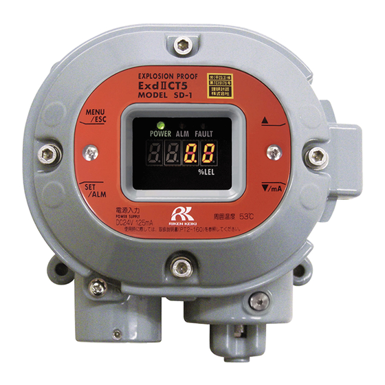
3 Product Components 3-2. Names and functions for each part 3-2. Names and functions for each part (6) Alarm lamp (7) Fault lamp (5) Power lamp (1) MENU/ESC key (3) key (8) Concentration value display (2) SET key (4) key Used to enter the maintenance mode. -
Page 12: Block Diagram
3 Product Components 3-3. Block diagram 3-3. Block diagram <Electric Diagram> Power supply part POWER INPUT (24 VDC) Display (POWER) (ALARM) (FAULT) Seven-segment LED Controller Alarm contact controller (four-digit) (CPU) Gas alarm contact (ALARM) Contact activation Magnetic operation part • De-energized (MENU/ESC) (▲) (▼) (SET) (De-energized at a normal environment) -
Page 13: How To Use
4 How to Use 4-1. Before using the detector How to Use 4-1. Before using the detector Not only the first-time users but also the users who have already used the product must follow the operating precautions. Ignoring the precautions may damage the detector, resulting in inaccurate gas detection. NOTE ・... -
Page 14: Precautions For System Designing
4 How to Use 4-3. Precautions for system designing Keep the detector (and its cables) away from noise source devices. When selecting installation points, avoid a place where high-frequency/high-voltage exist. Do not install the detector in a place where maintenance of the detector cannot be performed or where handling the detector involves dangers. - Page 15 4 How to Use 4-3. Precautions for system designing please contact the manufacturer.) In addition to lightning, there are more sources of surge noise. To protect units Grounding from these noise sources, the units must be grounded. * The lightning arrester has a circuit to remove a surge voltage which damages field devices, so that signals may be attenuated.
-
Page 16: How To Install
4 How to Use 4-4. How to install 4-4. How to install <Installation Dimensions and Maintenance Space> 150mm The following installation requirements must be met to install the detector. Attach the detector on the wall and others using four M5 screws. ... -
Page 17: Installation Procedure
(NPT1/2) WARNING Do not replace parts at your sole discretion but contact RIKEN KEIKI if the transparent window has a crack or the explosion-proof joint surface is abnormal, or the clamping screw or bolt is changed, lost etc. NOTE ・Our company-specified grease : BARRIERTA JFE 552 (manufactured by NOK KLUBER) -
Page 18: How To Wire
4 How to Use 4-6. How to wire 4-6. How to wire CAUTION Be careful not to damage the internal electronic circuit when wiring. In addition, be careful not to apply stresses on the detector when (overweight) cables are installed. ... - Page 19 4 How to Use 4-6. How to wire CAUTION The specified bare wire length must be observed when the wire insulation is peeled off. Improper clamping of the wire due to a shorter bare wire length may cause defective electrification or heating.
- Page 20 4 How to Use 4-6. How to wire <Grounding> Connect the detector to your grounding terminal with the external terminal WARNING Before turning on the detector, do not forget to connect it to a grounding terminal. For stable operation of the detector and safety, it must be connected to a grounding terminal. Do not connect the grounding wire to a gas pipe.
-
Page 21: How To Operate
5 How to Operate 5-1. Preparation for start-up How to Operate 5-1. Preparation for start-up Before supplying power, read and understand the following precautions. Ignoring these precautions may cause an electric shock or damage the detector. Connect the detector to a grounding circuit. ... -
Page 22: How To Start The Detector
5 How to Operate 5-3. How to start the detector WARNING When the detector enters other mode from the detection mode while an alarm is activated, the alarm is reset. 5-3. How to start the detector Before supplying power (24 VDC) to the detector, check that the detector is installed properly. ... -
Page 23: Modes
5 How to Operate 5-4. Modes 5-4. Modes Details on each mode are provided as follows. CAUTION Do not change the settings if not necessary. Changing the settings without understanding the specifications may cause malfunctions. Mode Item LED display Details Detection Normal state... -
Page 24: User Mode
5 How to Operate 5-5. User mode 5-5. User mode WARNING After the adjustment is completed, never fail to press MENU/ESC key to return to the detection mode. (If the detector remains in the user mode, it automatically returns to the detection mode in ten hours.) Show Various Settings - 22 -... - Page 25 5 How to Operate 5-5. User mode <Zero Adjustment "1-1"> This is used to perform the zero adjustment. NOTE If the zero calibration failed since the zero point was significantly fluctuated from around zero, it returns to 1-1 after FAIL rather than PASS is displayed. In this case, the zero adjustment has not been completed. - 23 -...
-
Page 26: How To Exit
5 How to Operate 5-6. How to exit <Setting Display "1-2"> Display various setting values. Press SET key. AL.: The contact is activated due to the gas alarm. FAU.: The contact is activated due to the fault alarm. A.orF.: The contact is activated due to the gas alarm or the fault alarm. -
Page 27: Operations And Functions
6 Operations and Functions 6-1. Gas alarm activation Operations and Functions 6-1. Gas alarm activation Gas alarm: Activated when the concentration of detected gas reaches or exceeds the alarm setpoint value. <<Auto-Reset>> NOTE The alarm setpoint is factory-set. Although the alarm delay time (standard: 2 seconds) works in the detector to prevent a false activation, it can be cancelled if not needed. -
Page 28: Fault Alarm Activation
6 Operations and Functions 6-2. Fault alarm activation <Response to Gas Alarm> A gas concentration value exceeds the alarm setpoint When a gas alarm is triggered, take actions in accordance with your management rules of gas alarm. Normally, take the following actions. ... -
Page 29: External Output Operation
6 Operations and Functions 6-3. External output operation 6-3. External output operation Signal Transmission System Electric current transmission (non-isolated) 4 – 20 mA Transmission Path CVVS Transmission Distance CVVS 1.25 mm : Maximum 1.25 km CVVS 2.0 mm : Maximum 2.0 km Connection Load Resistance Below 300 Ω... -
Page 30: Other Functions
6 Operations and Functions 6-4. Other functions 6-4. Other functions <Suppression Function> The sensors used with the detector are influenced by environmental changes (temperature, humidity, and other characteristics) or interference gases (interference characteristics) in no small measure, which affects the reading. Therefore, the reading might be fluctuated around zero even in a normal environment. This function obscures influences by environmental changes and interference gases around zero that have no meaning for your management rules of gas alarm. -
Page 31: Maintenance
7 Maintenance 7-1. Maintenance intervals and items Maintenance This is an important instrument for the purpose of safety. To maintain the performance of the detector and improve the reliability of safety, perform a regular maintenance. 7-1. Maintenance intervals and items ... - Page 32 7 Maintenance 7-1. Maintenance intervals and items Main Services Power Supply Checks the power supply voltage. Check Verifies that the power lamp lights up. (Verifies that relevant points can be identified on the system.) (When a UPS (uninterruptible power system) is used, checks the operation with the UPS (uninterruptible power system).) Concentration Verifies that the concentration display value is zero (or 20.9 vol% on the oxygen deficiency...
-
Page 33: Regular Maintenance Mode
7 Maintenance 7-2. Regular maintenance mode 7-2. Regular maintenance mode WARNING After the adjustment is completed, never fail to press MENU/ESC key to return to the detection mode. (If the detector remains in the maintenance mode, it automatically returns to the detection mode in ten hours.) Mode Item... - Page 34 7 Maintenance 7-2. Regular maintenance mode User Mode In "1-3.", press SET key. Then press SET key again for three seconds. Regular Maintenance Mode 2-0. Test Mode Test Mode Perform various tests. => P33 2-1. Zero Adjustment Zero Adjustment Perform the zero =>...
- Page 35 7 Maintenance 7-2. Regular maintenance mode <Alarm Test Mode "2-0"> Press SET key. Gas Test 2-0.0 Gas Test => P34 Alarm Test 2-0.1 Alarm Test => P34 Fault Test 2-0.2 Fault Test => P35 LED Test 2-0.3 LED Test => P35 Memory Test 2-0.4 Memory Test =>...
- Page 36 7 Maintenance 7-2. Regular maintenance mode <Gas Test "2-0.0"> 2-0.0 Press SET key. Introduce the test gas and perform the gas test. Stop introducing the test gas. When the reading drops, press MENU/ESC key to cancel the test and to go back to the original state.
- Page 37 7 Maintenance 7-2. Regular maintenance mode <Fault Alarm Test "2-0.2"> 2-0.2 Press SET key. Fault Test ON/OFF Select either ON/OFF. Switch ON and press SET key to activate the fault alarm. Return to OFF and press SET key to deactivate the fault alarm. (Pressing MENU/ESC key also enables to cancel this menu and to go back to the original state.)
- Page 38 7 Maintenance 7-2. Regular maintenance mode <Memory Test "2-0.4"> 2-0.4 Press SET key. When StA. is displayed, press SET key again. When CAL. is displayed, the memory diagnosis is performed. When memory is correct as a result of the diagnosis, PASS is displayed. Press SET key to go back to the original state.
- Page 39 7 Maintenance 7-2. Regular maintenance mode <Environmental Setting "2-4"> Set various operations and functions in the environmental setting. <<Environmental Setting 1>> 2-4. Environmental Setting Press SET key. 2-4.0 This is factory-set and not typically used by the user. 2-4.1 INHIBIT Setting Set INHIBIT.
-
Page 40: Gas Calibration Method
7 Maintenance 7-3. Gas calibration method 7-3. Gas calibration method Perform a gas calibration in each mode (zero adjustment <<SD-1>> mode and span adjustment mode) using the calibration gas. Zero adjustment gas Span adjustment gas (collected in a gas sampling bag) ... - Page 41 7 Maintenance 7-3. Gas calibration method Press SET key. Current Concentration Value Display Press SET key to perform the zero adjustment. Under Zero Adjustment (CAL. is displayed) Wait for a while until the adjustment is completed. Zero Adjustment Completed It automatically returns to 2-1 after PASS is displayed.
- Page 42 7 Maintenance 7-3. Gas calibration method <Span Adjustment "2-2"> This is used to perform the span adjustment. CAUTION Before starting the span adjustment, provide the detector with the span adjustment gas and wait until the indicator is stabilized. For the EN 60079-29-1 compliant specifications, use the gas with the concentration described in "10.1 Sensing target gas list"...
- Page 43 7 Maintenance 7-3. Gas calibration method NOTE If the span adjustment failed since the reading was significantly fluctuated from the introduced gas concentration, it returns to 2-2 after FAIL rather than PASS is displayed . In this case, the span adjustment has not been completed.
-
Page 44: Parts Replacement
7 Maintenance 7-4. Parts replacement 7-4. Parts replacement <Sensor Replacement> Gas sensor replacement is according to the following procedures. (1) Turn off the power supply (24V) to the detector. (2) After loosened set screw by hex wrench (nominal size 2),remove sensor guard by hex wrench (nominal size 6). - Page 45 7 Maintenance 7-4. Parts replacement <Replacement of Regular Replacement Parts> List of recommended regular replacement parts Maintenance Replacement Quantity Item intervals intervals (year) (pieces/unit) Rubber seal 6 months 3 - 8 years (for the sensor) NOTE The above replacement intervals are recommendation only. The intervals may change depending on the operating conditions.
-
Page 46: Storage, Relocation And Disposal
8 Storage, Relocation and Disposal 8-1. Procedures to store the detector or leave it for a long time Storage, Relocation and Disposal 8-1. Procedures to store the detector or leave it for a long time The detector must be stored under the following environmental conditions. ... -
Page 47: Troubleshooting
9 Troubleshooting 9 Troubleshooting Troubleshooting The troubleshooting does not explain the causes of all the malfunctions which occur on the detector. This simply helps to find the causes of malfunctions which frequently occur. If the detector shows a symptom which is not explained in this manual, or still has malfunctions even though remedial actions are taken, please contact our overseas sales department or local representatives. - Page 48 9 Troubleshooting 9 Troubleshooting <Abnormalities of Readings> Symptoms Causes Actions Drifting of sensor Perform the zero adjustment. output Disturbances by interference gases, such as solvents, cannot be eliminated completely. Presence of For information on actions, such as removal filter, please interference gas contact our overseas sales department or local The reading rises...
-
Page 49: Product Specifications
10 Product Specifications 10-1. List of specifications Product Specifications 10-1. List of specifications Model SD-1 Type TYPE GP MED EX Detection principle Catalytic combustion type Gas to be detected Methane Concentration display Seven-segment LED (four-digit) Detection range 0 - 100% LEL Display resolution 0.5% LEL Detection method... - Page 50 10 Product Specifications 10-1. List of specifications Outline Drawings - 48 -...
- Page 51 10 Product Specifications 10-1. List of specifications <Detectable gas list (MED approved)> Detectable gas Methane Gas code Measuring range 0-100 %LEL LEL concentration 4.4 vol% Alarm point 25.0 %LEL Operating temperature range -20 to +60℃ Air velocity range 0 to 6m/s Normal ±...
-
Page 52: List Of Accessories
10 Product Specifications 10-2. List of accessories 10-2. List of accessories Operating manual ......one Dedicated handling lever ....one Dedicated control key ....The supplied quantity depends on the number of units to be delivered. 1 to 10 units 11 to 20 units 21 to 50 units three... -
Page 53: Definition Of Terms
11 Definition of Terms 11 Definition of Terms Definition of Terms Catalytic This is a principle of the sensor installed in the detector head. combustion type See "10-3. Detection principle" for details. Output from the detector head fluctuates for a while after turning on the power. Initial clear This is a function to prevent triggering alarm during that time. - Page 54 Revision History Edition Revision Date issued First edition 8/18/2020 Complete revision 11/10/2020 Declaration of Conformity 11/12/2021 P22, 28, 29, 32, 33, 38 Deleted mention of negative suppression values 7/29/2022 2-4 UKEX added, CE DoC changed, UKCA DoC added 10/12/2023...
Need help?
Do you have a question about the SD-1 GP MED EX and is the answer not in the manual?
Questions and answers