Table of Contents
Advertisement
Quick Links
Advertisement
Table of Contents

Related Manuals for Riken Keiki NC-1000


Summary of Contents for Riken Keiki NC-1000
- Page 1 PT0E-1382 Portable Combustible Gas Detector NC-1000 Operating Manual (PT0-138)
-
Page 2: Table Of Contents
Contents 1. Outline of the Product ............................. 4 Preface ................................4 Purpose of use ..............................4 Definition of DANGER, WARNING, CAUTION and NOTE ................4 2. Important Notices on Safety ........................... 5 2-1. Danger cases............................5 2-2. Warning cases ............................6 2-3. - Page 3 12. Product Specifications ..........................72 12-1. List of product specifications ....................... 72 12-2. Optional part list ........................... 73 13. Appendix ..............................74 13-1. Definition of terms ..........................74 - 3 -...
-
Page 4: Outline Of The Product
Outline of the Product Preface Thank you for choosing our portable combustible gas detector NC-1000 (hereinafter referred to as the gas detector). Please check that the model number of the product you purchased is included in the specifications on this manual. -
Page 5: Important Notices On Safety
2. Important Notices on Safety 2-1. Danger cases Important Notices on Safety To maintain the performance and use the gas detector safely, observe the following instructions of DANGER, WARNING and CAUTION. 2-1. Danger cases DANGER About use While conducting measurement in a manhole or confined space, do not lean over or look into the manhole or closed space. -
Page 6: Warning Cases
2. Important Notices on Safety 2-2. Warning cases 2-2. Warning cases WARNING Sampling point pressure The gas detector is designed to draw gases under the atmospheric pressure. If excessive pressure is applied to the gas inlet (GAS IN) and outlet (GAS OUT) of the gas detector, measuring gases may leak out from its inside and may cause dangerous conditions. -
Page 7: Precautions
2. Important Notices on Safety 2-3. Precautions 2-3. Precautions - 7 -... - Page 8 2. Important Notices on Safety 2-3. Precautions - 8 -...
-
Page 9: Safety Information
2-4. Safety information 2-4. Safety information Outline of the product The combustible gas detector model NC-1000 is designed to detect leakage of combustible gases in a hazardous area continuously. The detection range of NC-1000 is 0 to 10,000 ppm. A sample of gas is drawn by the internal small pump. -
Page 10: Product Components
3-1. Main unit and standard accessories After opening the package, check the gas detector and accessories. If anything in the following list is not included, contact RIKEN KEIKI. Main unit For names and functions of individual parts of the gas detector and LCD display, see "Names and functions for each part"... - Page 11 3. Product Components 3-1. Main unit and standard accessories DANGER About explosion-proof Do not modify or change the circuit, structure, etc. When using the gas detector in a hazardous area, take the following countermeasures for preventing dangers resulting from electrostatic charges. (1) Wear anti-static clothes and conductive shoes (anti-static work shoes).
-
Page 12: Names And Functions For Each Part
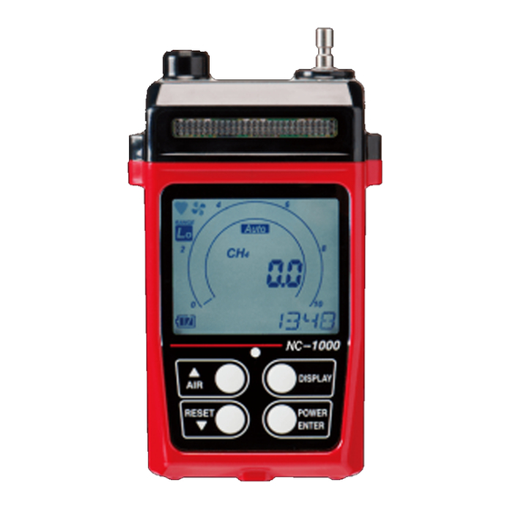
3. Product Components 3-2. Names and functions for each part 3-2. Names and functions for each part This section describes names and functions of main unit and battery unit parts and LCD display. <Appearance of Main Unit> (9) Gas outlet (8) Gas inlet (3) Alarm lamp window... - Page 13 3. Product Components 3-2. Names and functions for each part <LCD Display> (1) Operating state display (2) Flow check display (5) Gas name display (3) Range mode (6) Concentration and display unit display (4) Battery level icon (7) Full scale and bar display (8) Clock display Name...
- Page 14 3. Product Components 3-2. Names and functions for each part Gas sampling probe and gas sampling hose (1) Gas sampling probe (3) Hose (2) Gas sampling hose clamp coupler 差し替え Name Function Placed in a detection area to collect a gas. Gas sampling probe The probe includes a dust filter.
-
Page 15: How To Use
4. How to Use 4-1. Before using the gas detector How to Use 4-1. Before using the gas detector Not only the first-time users but also the users who have already used the gas detector must follow the operating precautions. Ignoring the precautions may damage the unit, resulting in inaccurate gas measurement. - Page 16 4. How to Use 4-2. Preparation for start-up Remove old batteries and Battery cover then put new batteries while observing the correct polarity. Close the battery cover and lock it. A clicking sound is heard when the cover is locked. DANGER ...
- Page 17 Main unit CAUTION Use only a gas sampling hose specified by RIKEN KEIKI. Use the gas detector with the gas sampling probe connected to the gas sampling hose so that no foreign substance is drawn into the gas sampling hose.
-
Page 18: How To Start The Detector
4. How to Use 4-3. How to start the detector 4-3. How to start the detector When the power is turned on, a self-diagnostic starts, and then the gas detector enters the detection mode. Power-on Press and hold the POWER button until the buzzer blips (one second or longer) to turn on the power. When the power is turned on, the LCD display changes automatically as shown below, and the gas detector enters the detection mode. - Page 19 4. How to Use 4-3. How to start the detector Full scale Display example: Display 10000 ppm ▼ WARNING Display example: setpoint 250 ppm display ▼ ALARM Display example: setpoint 500 ppm display ▼ Automatic air calibration Display ▼ The buzzer blips once and the Detection detection mode...
- Page 20 In this case, turn off the power and then turn it on again in an environment with fresh atmospheric air. If the situation does not improve after several times of power cycling, there may be a problem in the sensor. Contact RIKEN KEIKI immediately. Gas measurement cannot be performed with a faulty sensor.
-
Page 21: Basic Operating Procedures
RESET button after removing the cause of low flow rate. For other fault alarms, turn off the power and then promptly contact RIKEN KEIKI. The backlight goes off after 20 seconds or so of no operation. It lights up continuously while an alarm is activated. -
Page 22: Performing Air Calibration
4. How to Use 4-5. Performing air calibration 4-5. Performing air calibration Perform air calibration at maintenance before starting work or if the zero point deviates even though fresh air is drawn. * Before performing air calibration, check that the surrounding air is fresh. LCD display Press and hold the AIR button in the detection... -
Page 23: How To Detect
4. How to Use 4-6. How to detect 4-6. How to detect When the preparation for start-up and air calibration have been completed, put the probe close to the detection area in the detection mode and perform gas detection. Reading display (example) •... - Page 24 4. How to Use 4-6. How to detect NOTE Use only a gas sampling hose specified by RIKEN KEIKI. Use the gas detector with the gas sampling probe connected so that no foreign substance is drawn into it.
- Page 25 4. How to Use 4-6. How to detect Switching the range mode The range mode can be switched between the <Lo> low range (0 - 1000 ppm), <Auto> automatic switch and <Hi> high range (0 - 10000 ppm) to use the gas detector. <Auto>...
-
Page 26: Snap Logger
4. How to Use 4-7. Snap logger 4-7. Snap logger Any instantaneous value during measurement can be recorded. Up to 256 points of data can be recorded. When the number of recorded data points reaches the maximum, recorded data will be overwritten, starting from the oldest data. LCD display Press the ▼... -
Page 27: Power-Off
4. How to Use 4-8. Power-off ▼ The PEAK record is saved and To continue recording logs, then the station ID selection operate from the station ID screen is displayed. selection described in the step To end log recording, press the DISPLAY button to return to the detection mode. -
Page 28: Display Mode Setting
5. Display Mode Setting 5-1. Entering display mode Display Mode Setting 5-1. Entering display mode This mode allows users to view and change various display settings. LCD display Press the DISPLAY button in the detection mode. The peak display in the display mode appears. - Page 29 5. Display Mode Setting 5-1. Entering display mode Overview of display mode Item LCD display Details Displays the maximum concentration Peak display detected during the period from power-on to the point of checking. * To clear the peak display, press and hold the RESET button until "CLEAR - RELEASE"...
- Page 30 5. Display Mode Setting 5-1. Entering display mode Enters the user mode. Entering user mode (P. 40) Returns to the detection mode. Detection mode - 30 -...
-
Page 31: Concentration Displayed Gas Reading Setting
5. Display Mode Setting 5-2. Concentration displayed gas reading setting 5-2. Concentration displayed gas reading setting Normally, the concentration display of the gas detector is either "methane (CH4)" or "general combustible gases (HC)" depending on the specification; however, a pre-registered gas can be read instead to display its concentration. - Page 32 Therefore, request RIKEN KEIKI to perform calibration using the gas to be measured. See "NC-1000 gas list" in the following page for a list of gases available for reading. The gas detector provides two different specifications for target combustible gases: "general combustible gases (HC)"...
- Page 33 5. Display Mode Setting 5-2. Concentration displayed gas reading setting NC-1000 gas list Read Read Spiral Hose for Gas type Display from from hose solvent i-C4H10 Methane × Isobutane i-C4H10 Hydrogen ...
-
Page 34: Alarm Setpoint Display
5. Display Mode Setting 5-3. Alarm setpoint display 5-3. Alarm setpoint display The alarm setpoint display and alarm activation can be tested. LCD display ▼ Press the ENTER button. The alarm setpoint display appears. ▼ * Press the DISPLAY button to cancel the operation. - Page 35 5. Display Mode Setting 5-3. Alarm setpoint display Press the DISPLAY button. The display mode menu returns. ▼ - 35 -...
-
Page 36: Pump Suction Volume Setting
5. Display Mode Setting 5-4. Pump suction volume setting 5-4. Pump suction volume setting The pump suction volume can be set to L (Low: suction volume <low>) or H (High: suction volume <high>). LCD display ▼ Press the ENTER button. The pump suction volume setting mode is entered. - Page 37 5. Display Mode Setting 5-4. Pump suction volume setting NOTE When the gas detector is restarted, the pump suction volume is set to L (suction volume <low>). - 37 -...
-
Page 38: Log Data Display
5. Display Mode Setting 5-5. Log data display 5-5. Log data display The data recorded by the snap logger can be viewed. LCD display ▼ Press the ENTER button. The log data display appears. ▼ * Press the DISPLAY button to cancel the operation. - Page 39 5. Display Mode Setting 5-5. Log data display The contents of the selected log (gas name, BASE and PEAK record values and station ID) are displayed in turn. ▼ ▼ Press the DISPLAY button to end. The display mode menu returns. * To continue the log data display, press the ENTER button and repeat the steps from 2.
-
Page 40: User Mode Setting
6. User Mode Setting 6-1. Entering user mode User Mode Setting 6-1. Entering user mode The maintenance including internal clock correction can be performed. LCD display Press the DISPLAY button six times in the detection mode to enter the user mode. Press the ENTER button. - Page 41 6. User Mode Setting 6-1. Entering user mode NOTE The backlight goes off after 30 seconds or so of no operation. - 41 -...
- Page 42 6. User Mode Setting 6-1. Entering user mode Overview of user mode Item LCD display Details Turns on/off the display of blinking bar Peak bar display setting graph for the maximum concentration detected during the period from power-on to the point of checking on the bar graph. (P.
-
Page 43: Peak Bar Display Setting
6. User Mode Setting 6-2. Peak bar display setting 6-2. Peak bar display setting A peak of the detected gas concentration can be displayed on the bar. LCD display Press the ENTER button. The peak bar display setting mode is entered. Select <on>/<oFF>... -
Page 44: Date/Time Setting
6. User Mode Setting 6-3. Date/time setting 6-3. Date/time setting Set the date/time of the internal clock. LCD Display Press the ENTER button. The date/time setting mode is entered. Adjust the date/time using the ▲ or ▼ button and then press the ENTER button. -
Page 45: Calibration
7. Calibration 7-1. Preparation for air and span calibration Calibration 7-1. Preparation for air and span calibration Prepare the followings before performing maintenance such as bump test and air calibration. Preparation for air calibration Perform air calibration at maintenance before starting work or if the zero point deviates even though fresh air is drawn. - Page 46 7. Calibration 7-1. Preparation for air and span calibration CAUTION Do not use a lighter gas to check the sensitivity of the gas detector. A constituent of the lighter gas may deteriorate the sensor performances. - 46 -...
-
Page 47: Entering Calibration Mode
7. Calibration 7-2. Entering calibration mode 7-2. Entering calibration mode The maintenance including bump test and air calibration can be performed. LCD display Press and hold the ▼ and DISPLAY buttons together in the detection mode. The bump test screen in the calibration mode is displayed. - Page 48 7. Calibration 7-2. Entering calibration mode Overview of calibration mode Item LCD display Details Conducts the function test using a test Bump test gas. (P. 50) Performs air calibration (zero Air calibration adjustment). (P. 52) Automatically adjusts to the preset Auto calibration concentration value of the prepared calibration gas in a single step.
- Page 49 7. Calibration 7-2. Entering calibration mode Sets a password used to protect the Password setting entry to the calibration mode. (P. 59) To end, press the ENTER button to return Returning to detection to the detection mode. mode - 49 -...
-
Page 50: Bump Test
7. Calibration 7-3. Bump test 7-3. Bump test The function is tested using a test gas. The result will be displayed as "P" (Pass) or "F" (Failure). If the function is diagnosed as "F" (Failure), perform span calibration, etc. LCD display Press the ENTER button. - Page 51 7. Calibration 7-3. Bump test The gas detector returns to the calibration mode menu. - 51 -...
-
Page 52: Air Calibration
7. Calibration 7-4. Air calibration 7-4. Air calibration Perform the air calibration. LCD display Press the ENTER button. The air calibration mode is entered. Hold down the AIR button. Release the AIR button when the display changes from "AirCL - HOLD AIR"... -
Page 53: Auto Cal
7. Calibration 7-5. AUTO CAL 7-5. AUTO CAL This is how to preset the concentration value of the prepared calibration gas to the gas detector and perform calibration in a single step. LCD display Press the ENTER button. The AUTO CAL mode is entered. - Page 54 7. Calibration 7-5. AUTO CAL After span adjustment, the gas detector returns to the gas concentration display. ▼ After "END" is displayed, the gas detector returns to the calibration mode menu. (Buzzer: Once <blip>) Stop supplying the calibration gas. - 54 -...
-
Page 55: One Cal
7. Calibration 7-6. ONE CAL 7-6. ONE CAL This is how to perform calibration with manually set to the concentration value of the prepared calibration gas. LCD Display Press the ENTER button. The ONE CAL mode is entered. The concentration display blinks and the system waits for the calibration gas to be introduced. - Page 56 7. Calibration 7-6. ONE CAL Stop supplying the calibration gas. - 56 -...
-
Page 57: Bump Test Condition Setting
7. Calibration 7-7. Bump test condition setting 7-7. Bump test condition setting Various conditions for conducting a bump test can be set. LCD display Press the ENTER button. * Press the ▲ or ▼ button to The bump test condition setting select a desired menu and press mode is entered. - Page 58 7. Calibration 7-7. Bump test condition setting With "ESCAPE" displayed, press the ENTER button. The gas detector returns to the calibration mode menu. ▼ - 58 -...
-
Page 59: Password Setting
7. Calibration 7-8. Password setting 7-8. Password setting A password can be used to protect the entry to the calibration mode. LCD display Press the ENTER button. The password setting mode is entered. Specify the use of password using the ▲ or ▼... - Page 60 7. Calibration 7-8. Password setting - 60 -...
-
Page 61: Alarm Function
8. Alarm Function 8-1. Gas alarm activation Alarm Function 8-1. Gas alarm activation A "gas alarm" of the gas detector is triggered when the detected gas concentration reaches or exceeds an alarm setpoint, causing the alarm lamp to blink, the buzzer to sound, and the concentration display to blink. (Self-latching) There are three types of gas alarm: first alarm (WARNING), second alarm (ALARM) and over scale alarm (OVER). - Page 62 8. Alarm Function 8-1. Gas alarm activation <Alarm Lamp and Buzzer Operation Pattern> A slow or quick intermittent operation is performed depending on the alarm type. : 1 second interval : 0.5 second interval RESET Second alarm setpoint First alarm setpoint Time Alarm lamp...
-
Page 63: Fault Alarm Activation
LCD display If a fault alarm is triggered, determine the cause and take an appropriate action. If the gas detector has problems and is repeatedly malfunctioning, contact RIKEN KEIKI immediately. NOTE A low flow rate alarm (FAIL LOW FLOW) can be reset by pressing the RESET button. For other fault alarms, turn off the power and then promptly contact RIKEN KEIKI. -
Page 64: Maintenance
― check WARNING If an abnormality is found in the gas detector, contact RIKEN KEIKI immediately. NOTE Perform span adjustment using a calibration gas at least once every six months. The span adjustment requires dedicated equipment and creation of calibration gas. Therefore, contact RIKEN KEIKI for span adjustment. - Page 65 Our qualified service engineers have expertise and knowledge on the dedicated tools used for services, along with other products. To maintain the safety operation of the gas detector, please use our maintenance service. The followings are typical maintenance services. Contact RIKEN KEIKI for more information. <Main Services> Item...
-
Page 66: How To Clean
9. Maintenance 9-2. How to clean 9-2. How to clean Clean the gas detector if it becomes extremely dirty. The detector must be turned off while cleaning it. Use a waste cloth or the like to remove dust. Do not use water or organic solvent for cleaning because they may cause malfunctions. -
Page 67: Parts Replacement
* The operation must be checked after replacement by a qualified service engineer. For the stable operation of the gas detector and safety, ask a qualified service engineer to take care of replacement of the parts. Request it from RIKEN KEIKI. NOTE ... -
Page 68: Storage And Disposal
When the gas detector is used again after a long-period storage, be sure to perform a calibration. Contact RIKEN KEIKI for readjustment including calibration. 10-3. Disposal of products When the gas detector is disposed of, it must be treated properly as an industrial waste in accordance with the local regulations, etc. - Page 69 10. Storage and Disposal 10-3. Disposal of products <Disposal in EU Member States> When disposing of the gas detector in EU member states, sort the batteries as specified. Handle the removed batteries according to the classified refuse collection system and recycling system based on the regulations of EU member states.
-
Page 70: Troubleshooting
This simply helps to find the causes of malfunctions which may frequently occur. If the gas detector shows a symptom which is not explained in this manual, or still has malfunctions even though remedial actions are taken, please contact RIKEN KEIKI. 11-1. Abnormalities on unit... -
Page 71: Abnormalities Of Readings
Cycle the power several times. The pump The unit has not been used may start operating. If the situation does for a long time (six months not improve, request RIKEN KEIKI to or longer). replace the pump. Abnormalities of the internal... -
Page 72: Product Specifications
12. Product Specifications 12-1. List of product specifications Product Specifications 12-1. List of product specifications Model NC-1000 Gas to be Combustible gas (CH4, HC, etc. See the separate list for target gases) detected Detection New ceramic principle Measurement 0-10000 ppm... -
Page 73: Optional Part List
12. Product Specifications 12-2. Optional part list LCD backlight, data logger, log data display, peak display, Functions switching pump performance between strong and weak, changing a reading target Power supply: 4 AA alkaline dry batteries Accessories Storage: Hand strap Sampling: Gas sampling hose (1 m) and sampling probe * To meet the requirements for explosion-proof performance, use the batteries specified in the certification of explosion-proof electrical equipment. -
Page 74: Appendix
13. Appendix 13-1. Definition of terms Appendix 13-1. Definition of terms vol% Gas concentration indicated in the unit of one-hundredth of the volume Gas concentration indicated in the unit of one-millionth of the volume The acronym of Lower Explosive Limit. LEL refers to the lowest concentration of a combustible gas in air capable of causing explosion when ignited. - Page 75 - 75 -...
Need help?
Do you have a question about the NC-1000 and is the answer not in the manual?
Questions and answers