Riken Keiki SP-220 Series Operating Manual
Portable gas leak detector
Hide thumbs
Also See for SP-220 Series:
- Quick operating manual (2 pages) ,
- Operating manual (49 pages)

Related Manuals for Riken Keiki SP-220 Series


Summary of Contents for Riken Keiki SP-220 Series
- Page 1 PT0E-1435 Portable Gas Leak Detector SP-220 Series SP-220(TYPE M) SP-220(TYPE L) SP-220(TYPE ML) Operating Manual (PT0-139)
-
Page 2: Table Of Contents
Contents 1. Outline of the Product ............................. 3 Preface ................................3 Purpose of use ..............................3 Definition of DANGER, WARNING, CAUTION and NOTE ................3 How to check the standards and explosion-proof specifications ..............4 2. Important Notices on Safety ........................... 5 2-1. -
Page 3: Outline Of The Product
Outline of the Product Preface Thank you for choosing our portable gas leak detector SP-220 series (hereinafter referred to as the detector). Please check that the model number of the product you purchased is included in the specifications on this manual. -
Page 4: How To Check The Standards And Explosion-Proof Specifications
1. Outline of the Product How to check the standards and explosion-proof specifications How to check the standards and explosion-proof specifications The detector has different specifications depending on the standards or explosion-proof certification type. Check the specifications of the product you have before use. See the Declaration of Conformity at the end of this operating manual for CE marking specifications. -
Page 5: Important Notices On Safety
2. Important Notices on Safety 2-1. Danger cases Important Notices on Safety To maintain the performance and use the detector safely, observe the following instructions of DANGER, WARNING and CAUTION. 2-1. Danger cases DANGER About use While conducting measurement in a manhole or confined space, do not lean over or look into the manhole or closed space. -
Page 6: Warning Cases
2. Important Notices on Safety 2-2. Warning cases 2-2. Warning cases WARNING Sampling point pressure The concentration meter is designed to draw gases under the atmospheric pressure. If excessive pressure is applied to the gas inlet and outlet of the detector, measured gases may leak out from its inside and may cause dangerous conditions. -
Page 7: Precautions
2. Important Notices on Safety 2-3. Precautions 2-3. Precautions CAUTION Do not use the detector where it is exposed to oil, chemicals, etc. Do not submerge the detector under water on purpose. Do not use in a place where the detector is exposed to liquids such as oil and chemicals. ... - Page 8 2. Important Notices on Safety 2-3. Precautions CAUTION Others After a gas continuously comes into contact or a highly-concentrated gas comes into contact, the alarm pattern may continue. In such a case, draw cleaned air for more than five minutes (recommended) and perform air calibration again.
-
Page 9: Safety Information(For Atex/Iecex Specifications
B: Manufacturing month (1-9, XYZ for Oct.-Dec.) C: Manufacturing lot D: Serial number E: Factory code Manufacturer RIKEN KEIKI CO., LTD. 2-7-6 Azusawa, Itabashi-ku, Tokyo, 174-8744 Japan Web site: http://www.rikenkeiki.co.jp/ NOTE TOSHIBA AA alkaline batteries (LR6) can be used for TIIS specifications. -
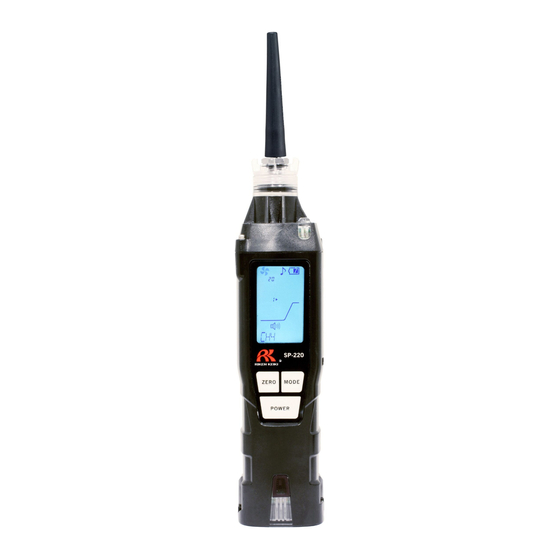
Page 10: Product Components
3. Product Components 3-1. Names and functions for each part Product Components 3-1. Names and functions for each part This section describes names and functions of main unit and battery unit parts and LCD display. Main unit (11) (10) Name Function Gas inlet Collects gases. - Page 11 Approx. 1g If there is anything missing, contact RIKEN KEIKI. CAUTION Do not remove the panel sheet on the display. The water-proof and dust-proof performances will be deteriorated. Do not affix a label or the like on the infrared port. Infrared communications can no longer be conducted.
- Page 12 3. Product Components 3-1. Names and functions for each part LCD display Name Function Operating state display Displays the operating status in the detection mode. Normal: Blinking Flow check display Displays the drawing status. Normal: Rotating Gas concentration Displays gas concentration and unit. display Alarm sound display Displays the setting status of the alarm sound.
-
Page 13: How To Use
4. How to Use 4-1. Before using the detector How to Use 4-1. Before using the detector Not only the first-time users but also the users who have already used the detector must follow the operating precautions. Ignoring the precautions may damage the unit, resulting in inaccurate gas measurement. 4-2. - Page 14 4. How to Use 4-3. How to replace the batteries CAUTION Never fail to turn off the power of the detector before replacing the batteries. Replace the batteries in a safe place. Replace both of the two batteries with new ones at one time. ...
-
Page 15: How To Start The Detector
4. How to Use 4-4. How to start the detector 4-4. How to start the detector When the power is turned on, a self-diagnostic starts, and then the detector enters the detection mode. Power-on Press and hold the POWER button until the buzzer blips (one second or longer) to turn on the power. When the power is turned on, the LCD display changes automatically as shown below, and the detector enters the detection mode. - Page 16 4. How to Use 4-4. How to start the detector * The date/time display is displayed only when the clock function is enabled. It is not displayed because the clock function is disabled by default. To enable the clock function, see "6-3. Clock function ON/OFF setting" on page 31. NOTE ...
-
Page 17: Basic Operating Procedures
4. How to Use 4-5. Basic operating procedures 4-5. Basic operating procedures The detection mode is used after power-on. (Display example: For city gases) MODE button AIR + POWER buttons Hold down for Hold down for Hold down for 3 secs 1 sec 3 secs Illumination... -
Page 18: How To Detect
4. How to Use 4-6. How to detect 4-6. How to detect Put the tip of the taper nozzle close to the detection area in the detection mode and perform gas detection. If a gas is drawn, the detected gas concentration is displayed with the bar meter on the LCD display. DANGER ... -
Page 19: Change Of The Alarm Setpoint
4. How to Use 4-7. Change of the alarm setpoint 4-7. Change of the alarm setpoint In the detector, the alarm setpoint of city gas (CH4) and LP gas (LPG) is factory set to 30 ppm. The alarm setpoint can be changed, depending on the purpose, in five levels. How to change the alarm setpoint 1 In the detection mode, press the AIR and MODE buttons at the same time. -
Page 20: Performing Air Calibration
4. How to Use 4-8. Performing air calibration 4-8. Performing air calibration After a high-concentration gas is detected or an alarm is triggered by temperature/humidity changes, perform air calibration in the measured atmosphere. * Before performing air calibration, check that the surrounding air is fresh. (Display example: For city gases) In the detection mode, hold down the AIR button. -
Page 21: Snap Logger
4. How to Use 4-9. Snap logger NOTE Perform air calibration under pressure and temperature/humidity conditions close to those in the operating environment and in fresh air. Perform air calibration after the reading is stabilized. If there is a sudden temperature change between the storage and operational locations, turn on the power of the detector, let it stand for five minutes or more in a similar environment to the operational location, and perform air calibration in fresh air before using it. -
Page 22: Peak Hold Function
4. How to Use 4-10. Peak hold function 4-10. Peak hold function When the peak hold function is enabled, the latest peak value is always displayed with the bar meter. (Display example: For city gases) In the detection mode, hold down the MODE button (for three seconds or longer). -
Page 23: How To Turn On The Illumination Lamp
4. How to Use 4-12. How to turn on the illumination lamp 4-12. How to turn on the illumination lamp The illumination lamp can be turned on when a measuring place is dark or in other situation. Hold down the AIR and POWER buttons at the same time (for three seconds or longer). -
Page 24: How To Set Display Mode
5. How to Set Display Mode 5-1. Entering the display mode How to Set Display Mode 5-1. Entering the display mode This mode allows users to view and change various display settings and perform other operation. (Display example: For city gases) In the detection mode, press the MODE button. - Page 25 5. How to Set Display Mode 5-1. Entering the display mode Display mode overview Item LCD display Details Displays the maximum concentration Peak display detected during the period from power-on to the point of checking. * To clear the peak display, hold down the AIR button until "PEAK CLR"...
-
Page 26: Measured Gas Switching Setting
5. How to Set Display Mode 5-2. Measured gas switching setting 5-2. Measured gas switching setting Normally, the concentration display of the detector is "CH4 or LPG" by default depending on the specifications; however, the display can be switched between LPG and CH4 according to the specifications to detect its concentration. -
Page 27: Log Data Display
5. How to Set Display Mode 5-3. Log data display 5-3. Log data display The data recorded by the snap logger can be viewed. The "REC DATA" screen is displayed only when the clock function is enabled (See "6-3. Clock function ON/OFF setting"... -
Page 28: How To Set User Mode
6. How to Set User Mode 6-1. Entering the user mode How to Set User Mode 6-1. Entering the user mode The maintenance including internal clock correction, etc. can be performed. (Display example: For city gases) In the detection mode, press the MODE button a few times to display "USER"... - Page 29 6. How to Set User Mode 6-1. Entering the user mode User mode overview Item LCD display Details Set the date/time of the internal clock. Date/time setting (P. 30) * When the clock function is disabled, the date/time setting screen is not displayed.
-
Page 30: Date/Time Setting
6. How to Set User Mode 6-2. Date/time setting 6-2. Date/time setting Set the date/time of the internal clock. The date/time setting screen is displayed only when the clock function is enabled. Enable the clock function in "6-3. Clock function ON/OFF setting" on page 31 before setting the date/time. On the "DATE"... -
Page 31: Clock Function On/Off Setting
6. How to Set User Mode 6-3. Clock function ON/OFF setting 6-3. Clock function ON/OFF setting Enable or disable the clock function. The clock function is disabled by default. If the date/time needs to be displayed on start-up or the snap logger function is used, enable the clock function. -
Page 32: Alarm Function
Blip-blip, blip-blip Display example of low flow rate (LOW FLOW) LCD display If a fault alarm is triggered, determine the cause and take appropriate action. If the unit has problems and is repeatedly malfunctioning, contact RIKEN KEIKI immediately. - 32 -... -
Page 33: Maintenance
8. Maintenance 8-1. Maintenance intervals and items The recorded data can be read out by the "Data Logger Management Program" (optional). See the operating manual of "Data Logger Management Program" for more information. Maintenance The detector is a precision devices. To maintain the performance of the detector and improve the reliability of detecting leakage, perform a regular maintenance. - Page 34 Our qualified service engineers have expertise, knowledge and other information on the dedicated tools used for services, along with other products. To maintain the safety operation of the unit, please use our maintenance service. The followings are typical maintenance services. For details, contact RIKEN KEIKI. <Main Services> Item...
-
Page 35: How To Clean
8. Maintenance 8-2. How to clean 8-2. How to clean Clean the detector if it becomes extremely dirty. The detector must be turned off while cleaning it. Use a waste cloth or the like to remove dust. Do not use water or organic solvent for cleaning because they may cause malfunctions. - Page 36 8. Maintenance 8-3. Parts replacement Replace the filter placed inside the rubber seal with a new one. Filter Rubber seal Attach the rubber seal with the filter attached, to the cap. At this time, check that the rib has been firmly inserted into the groove.
- Page 37 The sensor life has expired if, for example, the sensors cannot be calibrated in span adjustment, the readings do not come back after air calibration, or the readings fluctuate. In this case, contact RIKEN KEIKI. Battery replacement For battery replacement, see "How to replace the batteries" on page 13.
-
Page 38: Storage And Disposal
9-2. Procedures to use the detector again CAUTION When the detector is used again after a long-period storage, never fail to perform a calibration. Contact RIKEN KEIKI for information on readjustment including calibration. - 38 -... -
Page 39: Disposal Of Products
9. Storage and Disposal 9-3. Disposal of products 9-3. Disposal of products When the detector is disposed of, it must be treated properly as an industrial waste in accordance with the local regulations, etc. WARNING Dispose of dry batteries in accordance with procedure specified by the local authority. <Disposal in EU Member States>... -
Page 40: Troubleshooting
If the detector shows a symptom which is not explained in this manual, or still has malfunctions even though remedial actions are taken, please contact RIKEN KEIKI. <Abnormalities on Unit>... - Page 41 Abnormalities of the internal Clock abnormalities the built-in clock is seemingly clock FAIL CLOCK malfunctioning. Thus, it must be replaced. Request RIKEN KEIKI for repair. Pump abnormalities Abnormalities of the pump Request RIKEN KEIKI for repair. FAIL PUMP - 41 -...
-
Page 42: Product Specifications
11. Product Specifications Product Specifications Model SP-220(TYPE M) SP-220 (TYPE L) SP-220 (TYPE ML) Detection principle Hot-wire semiconductor Gas to be detected City gas City gas/LPG (Switchable to LPG) (Switchable to city (Switched) gas) Calibration gas City gas (CH4) LPG (i-C4H10) LPG (i-C4H10) calibration calibration calibration... -
Page 43: Appendix
12. Appendix Appendix 12-1. Definition of terms Gas concentration indicated in the unit of one-hundredth of the volume vol% Gas concentration indicated in the unit of one-millionth of the volume The acronym of Lower Explosive Limit. Lower explosive limit (LEL) refers to the lowest concentration of a combustible gas in air capable of causing explosion when ignited. - Page 44 12. Appendix 12-1. Definition of terms - 44 -...
Need help?
Do you have a question about the SP-220 Series and is the answer not in the manual?
Questions and answers