Table of Contents
Advertisement
Quick Links
INDUSTRIAL SHREDDER
HDD Gladiator
INSTRUCTION MANUAL
FOR USE AND MAINTENANCE
ORIGINAL INSTRUCTIONS
U
. S
SE MINERAL OIL
EE
T
5-1 P
52
ABLE
AGE
It is compulsory for the personnel in charge of the installation, running and maintenance of the
shredder to read the present text before starting whatever operation.
intimus International GmbH declines any responsibility should the user make any
alterations to the shredder or use it in ways other than those indicated in this manual.
A copy of this manual with all its enclosures should always be on hand for the personnel in
charge of the machine to be consulted and therefore should be kept nearby the shredder in a
clearly visible position and protected by a cover aimed at preventing it from deteriorating.
Under the law which protects the copyright of such content cannot be made any use by third
parties without the prior written consent of the owner. Is expressly prohibited reproduction, by
any means, including electronic, as well as any content editing, publication, transmission,
distribution or uploading.
This publication can be changed without advise unless the modifications are pertaining to the
safety of the machinery (configurations and requirements) holding by the customer.
95399 1 11/18
1 / 83
Advertisement
Table of Contents

Related Manuals for Intimus HDD Gladiator


Summary of Contents for Intimus HDD Gladiator
- Page 1 It is compulsory for the personnel in charge of the installation, running and maintenance of the shredder to read the present text before starting whatever operation. intimus International GmbH declines any responsibility should the user make any alterations to the shredder or use it in ways other than those indicated in this manual.
- Page 2 88677 Markdorf – Germany Address Tel. +49 (0)7544 600 / Fax +49 (0)7544 60248 E-Mail: sales.de@intimus.com / web: www.intimus.com Machine Industrial Shredder Model HDD Gladiator STID No. 424818 Year of construction 2018 5 blades, 1 hook, thickness 29 mm and 11 blades, 11 hooks,...
- Page 3 INDUSTRIAL SHREDDER Instruction for use and maintenance Table 1-2 – Objects to be supplied Objects of this supply Industrial shredder mod. HDD Gladiator Electric switchboard with control panel s/n 2018-07 Feeding hopper with loading drawer Support stand 95399 1 11/18...
- Page 4 INDUSTRIAL SHREDDER Instruction for use and maintenance LIST OF REVISIONS Revisions 95399 1 11/18 First edition 95399 1 11/18 4 / 83...
-
Page 5: Table Of Contents
INDUSTRIAL SHREDDER Instruction for use and maintenance TABLE OF CONTENTS 1. GENERAL INFORMATION ................11 INTRODUCTION ........................11 1.1.1 Partly completed machinery ....................11 GUARANTEE ........................12 CUSTOMER’S RESPONSIBILITIES ..................12 TECHNICAL ASSISTANCE ....................13 SPARE PARTS ........................13 CONVENTIONAL GRAPHICS AND GLOSSARY ..............13 TECHNICAL STANDARDS APPLIED ................... - Page 6 Instruction for use and maintenance 4.2.1 Table of lifting chain ......................48 4.2.2 Lifting of the shredding chamber for series HDD Gladiator......... 49 WIRINGS TO THE MAINS ....................50 5. SETTING AND FIRST STARTING ..............51 PREPARATION, INSPECTIONS AND TESTS BEFORE START-UP........51 5.1.1...
- Page 7 INDUSTRIAL SHREDDER Instruction for use and maintenance 9. ATTACHMENT ....................83 95399 1 11/18 7 / 83...
- Page 8 Figure 3-1 – Operating Principle – Product to be supplied ..............32 Figure 3-2 – Main units for series HDD Gladiator - Typical ............. 34 Figure 3-3 – Main units for series HDD Gladiator – Product to be supplied ........35 Figure 3-4 – Supporting stand (Typical) ....................36 Figure 3-5 –...
- Page 9 INDUSTRIAL SHREDDER Instruction for use and maintenance LIST OF TABLES Table 1-1 – Technical data ........................II Table 1-2 – Objects to be supplied ......................III Table 1-1 – Shredder 3HP series ......................16 Table 2-1- Table of risks, dangers and protection measures present ........... 23 Table 2-2 –...
- Page 10 INDUSTRIAL SHREDDER Instruction for use and maintenance This page is left intentionally blank 95399 1 11/18 10 / 83...
-
Page 11: General Information
CAUTION In these instructions are described the components that intimus uses for the setting of the standard machinery. Also the components not delivered are descripted as example and suggestion for a correct assembly. -
Page 12: Guarantee
Instruction for use and maintenance 1.2 GUARANTEE intimus International GmbH grants the Purchaser a warranty for defects of machinery which has a duration of twelve months from the date of initial start for use of the machinery not exceeding 8 (eight) hours per day for five (5) days per week or 1800 work hours of the machine and in any case not later than fifteen months from the date of delivery, depending on the case that occurs first (see attached Warranty Certificate). -
Page 13: Technical Assistance
INDUSTRIAL SHREDDER Instruction for use and maintenance 1.4 TECHNICAL ASSISTANCE Technical assistance can be provided exclusively by the manufacturer’s personnel, or by personnel authorized by the manufacturer. Requests for technical assistance should be sent in writing to the address of the manufacturer and must always state: •... - Page 14 INDUSTRIAL SHREDDER Instruction for use and maintenance To allow this manual to be fully understood, we hereby list the terms used: • HAZARDOUS AREA: the area inside or near the machine, in which the presence of an exposed person puts the safety and health of the same at risk. •...
-
Page 15: Technical Standards Applied
INDUSTRIAL SHREDDER Instruction for use and maintenance 1.7 TECHNICAL STANDARDS APPLIED In the design and realization stages of this machine, reference was made to the following standards and documents: • 2006/42 E.E.C. Directive for Machines • UNI EN ISO 12100:2010: Safety of machinery - Basic concepts, general principles for design. -
Page 16: Shredder Cross-Reference
INDUSTRIAL SHREDDER Instruction for use and maintenance 1.9 SHREDDER CROSS-REFERENCE Table 1-1 – Shredder 3HP series SHREDDER POWER INTIMUS CODE SHAFTS NUMBER HDD Gladiator 95399 1 11/18 16 / 83... -
Page 17: Safety And Accident Prevention
INDUSTRIAL SHREDDER Instruction for use and maintenance SAFETY AND ACCIDENT PREVENTION 2.1 GENERAL INFORMATION • The manual must be read entirely and understood by all the operators, who, either full- time or occasionally, are in charge of installing, running and carrying out maintenance on the shredder or its dismantling. -
Page 18: Intended Use
INDUSTRIAL SHREDDER Instruction for use and maintenance 2.2 INTENDED USE Shredders are machines that can be used in many fields for different purposes: recycling, size reduction, destruction and disposing of industrial and urban waste. Should the sales contract establish the characteristics of the material to be shredded and the machine capacity;... -
Page 19: Incorrect And/Or Improper Use And Behaviour
It must not be operated also: • without oil or with overused oil (see paragraph 5.1.5 Oil and grease lubrication before starting HDD Gladiator); • if blades are not perfectly tightened (see Chapter 7, Tightening the blades’ pack for each series of shredder);... -
Page 20: Explosive Atmosphere
"improper use", therefore intimus International GmbH declines any responsibility for damage or accidents caused by failure in complying with the instructions supplied, and will consider any guarantee on the machine cancelled in such cases. DANGER It’s strictly prohibited getting near the screen with every part of the body during the machine working (single shaft shredders tipically). -
Page 21: Risks, Protections, Warnings And Notices
INDUSTRIAL SHREDDER Instruction for use and maintenance 2.6 RISKS, PROTECTIONS, WARNINGS AND NOTICES 2.6.1 General Safety The machine which has been installed by following the indications given in this manual (see Chapter 4 INSTRUCTIONS FOR INSTALLATION) and handled by operators according to these instructions cannot be the cause of accidents. -
Page 22: Figure 2-1 - Safety Devices Installed - Product To Be Supplied
INDUSTRIAL SHREDDER Instruction for use and maintenance Supporting stand closing grids and door The supporting stand is surrounded and closed by a protection grid, which is fixed on 3 sides and has openable doors on the fourth side (loading). The interlocked safety micro switches are installed on the doors, which interrupt the shredder operation when they are opened. -
Page 23: Table 2-1- Table Of Risks, Dangers And Protection Measures Present
INDUSTRIAL SHREDDER Instruction for use and maintenance Table 2-1- Table of risks, dangers and protection measures present Pos. Description and protection from risks Danger Example image Load hopper with loading drawer: this prevents the projection of the material outwards during the shredding phase. Doors with protective grid: they prevent shredded material... - Page 24 INDUSTRIAL SHREDDER Instruction for use and maintenance Pos. Description and protection from risks Danger Example image Loading hopper: blade shafts in rotation. Shredded material discharge: area beneath intrinsically dangerous shredder due to rotating blade shafts. Electrical panel: dangerous area due to a live electrical panel 95399 1 11/18 24 / 83...
-
Page 25: Risks In The Environment Where The Shredder Is Installed
INDUSTRIAL SHREDDER Instruction for use and maintenance 2.6.2 Risks in the environment where the shredder is installed Should the shredder be used to process substances which, after working on, can cause a degradation in the environment in which the machine is installed (e.g. emission of dust in large quantities, harmful or irritating substances etc.) it will become necessary to carry out an adequate environment protection by using air suction or other suitable systems to do away with the polluting effects. -
Page 26: Residual Risks
INDUSTRIAL SHREDDER Instruction for use and maintenance 2.6.3 Residual risks During the operations the shredder is all segregated with safety protections. The warning plates applied on the shredder regarding the residual risks may not be removed. 2.6.3.1 During the normal running operations Gear boxes Occasionally, the surface temperature of these components can rise over 85°C due to malfunction of the power-train or cooling system. -
Page 27: Warning And Accident Prevention Plates
INDUSTRIAL SHREDDER Instruction for use and maintenance 2.6.4 Warning and accident prevention plates The machine will be supplied with graphic elements placed by the manufacturer to indicate any danger, prohibition or warning. The graphic symbols used and their explanation are listed hereafter. DANGER We remind and underline that it is absolutely forbidden to mishandle or remove the protections and the warning plates. - Page 28 INDUSTRIAL SHREDDER Instruction for use and maintenance SYMBOL HAZARDS INVOLVED It is forbidden to direct jets of water at electrical equipments. Do not use water jets Ban on carrying out operations with live supply voltage for works in progress Do not go up or down the top side of Shredder inside the Segregated zone, Feeding Hopper Danger.
-
Page 29: Prearrangements For Installation
Upon starting working again after a long period of inactivity, lubricate the blades with oil at the first starting, as specified in paragraph 5.2 FIRST START-UP (NO LOAD START-UP). This intimus shredder may work at room temperatures varying from 0°C to 50°C. CAUTION If ambient temperature read the indicates MAX and MIN do not touch the machinery surfaces without protection (gloves). -
Page 30: Lighting
INDUSTRIAL SHREDDER Instruction for use and maintenance 2.7.3 Lighting For use in normal working conditions, the room where the shredder is installed must be lit in such a way as to make it possible to see the command panel without difficulty and, more in detail, the emergency push-button. -
Page 31: Description Of Shredder And Technical Details
INDUSTRIAL SHREDDER Instruction for use and maintenance DESCRIPTION OF SHREDDER AND TECHNICAL DETAILS 3.1 GENERAL DESCRIPTION OF SHREDDER The shredder consists of a shredding chamber which contains two or three rotating shafts supplied with one or more hook circular blades of different thicknesses, depending on the material for which the shredder is used. -
Page 32: Operating Principle
INDUSTRIAL SHREDDER Instruction for use and maintenance 3.2 OPERATING PRINCIPLE The material to be treated is sent into the feeding hopper which conveys it to the shredding chamber. The two blade holding shafts, while rotating, take the material towards the centre, the blades catch onto the material with the beaks placed on their circumference and cut it. -
Page 33: Electronic Control
INDUSTRIAL SHREDDER Instruction for use and maintenance 3.2.1 Electronic control All the machine working stages are controlled by a P.C. board. This controls the automatic reverse cycle if overloading occurs, and also allows for the activation of some special functions: •... -
Page 34: Main Units Of The Shredder
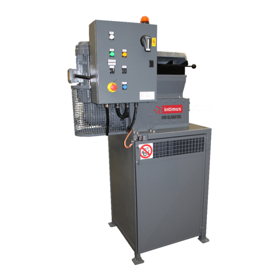
1. Feeding hopper 4. Supporting stand 2. Shredding chamber 5. Switchboard and control panel 3. Electric motor – 3 Kw 6. Manual Ram (Option) Figure 3-2 – Main units for series HDD Gladiator - Typical 95399 1 11/18 34 / 83... -
Page 35: Figure 3-3 - Main Units For Series Hdd Gladiator - Product To Be Supplied
2. Shredding chamber 5. Switchboard and control panel 3. Electric motor – 3 Kw 6. Planetary gearbox with grid protection Figure 3-3 – Main units for series HDD Gladiator – Product to be supplied 95399 1 11/18 35 / 83... -
Page 36: Description Of The Main Components
INDUSTRIAL SHREDDER Instruction for use and maintenance 3.4 DESCRIPTION OF THE MAIN COMPONENTS 3.4.1 Supporting stand The shredder rests on a stand made of electrically welded steel shaped plates. The stands are always closed on three sides by a fixed protection grid, whereas one side is furnished with grid doors with manual lever lock and safety micro switches. -
Page 37: Feeding Hopper
1. Hopper 2. Inspection panel 3. Manual Ram (Optional) Figure 3-5 – Hopper for series HDD Gladiator - Typical 95399 1 11/18 37 / 83... -
Page 38: Figure 3-6 - Hopper For Series Hdd Gladiator - Product To Be Supplied
For checking the shredding chamber, please see paragraph 7.3.8 - pack Check and inspection of the blades 1. Hopper body 2. Loading drawer 2. Hopper cover (openable) 3. Handle Figure 3-6 – Hopper for series HDD Gladiator – Product to be supplied 95399 1 11/18 38 / 83... -
Page 39: Shredding Chamber
It is a cast box consisting of the components as follows. A. Reduction unit E. Blades B. Frames F. Spacers C. Front flange G. Cleaning sectors D. Blade-holding shaft Figure 3-7 – Chamber for series HDD Gladiator 95399 1 11/18 39 / 83... -
Page 40: Motor Drive
The shredder is driven by an electric motor, which is coupled to the gear reduction unit. 1. Electric motor – 3 kW 2. Fixing bolts 3. Gearmotor Figure 3-8 – Motor drive for series HDD Gladiator 95399 1 11/18 40 / 83... -
Page 41: Electric System
INDUSTRIAL SHREDDER Instruction for use and maintenance 3.4.5 Electric system The electric system is set for star-delta starting. The electric system consists of: • a main power switch; • a thermal relay for the protection of the electric motor; • a “forward running”... -
Page 42: Technical Features
Instruction for use and maintenance 3.5 TECHNICAL FEATURES 3.5.1 Weights table Table 3-1 – Weights [kg] - Typical SHREDDER HDD Gladiator Table 3-2 – Weights [kg] – Product to be supplied SHREDDER HDD Gladiator 95399 1 11/18 42 / 83... -
Page 43: Dimensions Table
INDUSTRIAL SHREDDER Instruction for use and maintenance 3.5.2 Dimensions table Table 3-3 – Dimensions [cm] - Typical SHREDDER HDD Gladiator 90X39X74 76X76X91 44X53X67 40X50X18 Table 3-4 – Dimensions [cm] – Product to be supplied SHREDDER HDD Gladiator 98x39x74 76X76X107 36x64x35... -
Page 44: Declaration Of The Sound Emission Values
3.6 DECLARATION OF THE SOUND EMISSION VALUES The sound emission is considered with the shredder works without load in maximum nominal speed. Table 3-5 – Level of average acoustic pressure SHREDDER SERIES SOUND PRESSURE dB(A) HDD Gladiator 66,4 95399 1 11/18 44 / 83... -
Page 45: Instructions For Installation
INDUSTRIAL SHREDDER Instruction for use and maintenance INSTRUCTIONS FOR INSTALLATION 4.1 PACKING, HANDLING, SHIPMENT AND TRANSPORT 4.1.1 Packing and shipment The shredder is dismantled in the main parts upon shipment: hopper, shredding chamber, switchboard, and supporting stand. The machine, depending on the case, is delivered in one of the following arrangements: Sufficiently blocked and covered on a truck, unpacked. -
Page 46: Prearrangements For Installation
INDUSTRIAL SHREDDER Instruction for use and maintenance 4.1.4 Prearrangements for installation Before starting assembly operations, make sure that the flooring can sustain the shredder's weight (see Table 3-1 – Weights) also considering the coefficient of security stated by the regulations in force. The shredder must be installed on a suitable site, such as to allow normal machine running operations and routine maintenance (see the attached drawing and paragraph 2.7.2 Installation site). -
Page 47: Lifting And Assembly Of The Shredder
INDUSTRIAL SHREDDER Instruction for use and maintenance 4.2 LIFTING AND ASSEMBLY OF THE SHREDDER DANGER The shredder chamber cannot be lifted by hooking onto the hopper, nor the wholly assembled machine can be lifted this way, since the hopper hooking holes are not foreseen to withstand the whole machine weight. Refer to the attached drawing for details. -
Page 48: Table Of Lifting Chain
4.2.1 Table of lifting chain Table 4-1 – Assembly of the Shredder – Lifting Chain SHREDDER CHAIN CHAIN CHAIN MIN. REFER TO MODEL REFERENCE LENGTH LOAD 550mm 630mm 700kg Figure 4-1 HDD Gladiator 630mm 95399 1 11/18 48 / 83... -
Page 49: Lifting Of The Shredding Chamber For Series Hdd Gladiator
INDUSTRIAL SHREDDER Instruction for use and maintenance 4.2.2 Lifting of the shredding chamber for series HDD Gladiator Figure 4-1 – How to lift the shredding chamber for series HDD Gladiator 95399 1 11/18 49 / 83... -
Page 50: Wirings To The Mains
INDUSTRIAL SHREDDER Instruction for use and maintenance 4.3 WIRINGS TO THE MAINS IMPORTANT NOTICE This action must be carried out by a qualified technician (electrician) in full compliance with the Standard in force. Before connecting the machine to the mains it is necessary to: •... -
Page 51: Setting And First Starting
INDUSTRIAL SHREDDER Instruction for use and maintenance SETTING AND FIRST STARTING 5.1 PREPARATION, INSPECTIONS AND TESTS BEFORE START-UP. Before starting work, carry out a first no-load running of the machine. Furthermore, proceed with the following controls: 5.1.1 Grid holder (if installed) or rotating screen (if installed) CAUTION Before starting the shredder always check that the bolts which secure the grid-holder to the shredding chamber are perfectly tightened. -
Page 52: Oil And Grease Lubrication Before Starting Hdd Gladiator
INDUSTRIAL SHREDDER Instruction for use and maintenance 5.1.5 Oil and grease lubrication before starting HDD Gladiator CAUTION The shredder can be supplied either with or without oils, depending on transport distances and specific agreement with the customer. The quantities reported in the Table 5-1 are indicative; always proceed with filling until the level indicators or plugs level is reached. -
Page 53: Figure 5-1 - Oil/Grease Lubrication Zones For Series Hdd Gladiator
INDUSTRIAL SHREDDER Instruction for use and maintenance A= Oils filling plug, B= Oil Level indicators, C= Oil Draining taps, D= Grease filling plug Figure 5-1 – Oil/grease Lubrication Zones for series HDD Gladiator 95399 1 11/18 53 / 83... -
Page 54: First Start-Up (No Load Start-Up)
INDUSTRIAL SHREDDER Instruction for use and maintenance 5.2 FIRST START-UP (NO LOAD START-UP) IMPORTANT INFORMATION The start sequence is also reproduced in general terms in the attached flowchart. See chapter 9. CAUTION The no-load running of the shredder with new blades must be limited to the few minutes that are deemed necessary to check the machine for proper operation, otherwise the possible friction in-between the new blades can overheat them endangering their life severely. -
Page 55: Adjustments On Board Of The Shredder (Except For F10Ri Series)
INDUSTRIAL SHREDDER Instruction for use and maintenance 5.3 ADJUSTMENTS ON BOARD OF THE SHREDDER (EXCEPT FOR F10RI SERIES) CAUTION Since the adjustments on the electronic controls are particularly delicate they are carried out only by the manufacturer at the machine start-up. -
Page 56: Electrical Tests On The Shredder
EN 60204. The customer test results must be send to intimus Technical Service. CAUTION If this data will be missing by the Customer intimus International GmbH will cancel any guarantee on the machine. 95399 1 11/18 56 / 83... -
Page 57: Shredder Operation
INDUSTRIAL SHREDDER Instruction for use and maintenance SHREDDER OPERATION At this point, once the first no-load run has been carried out and the relative checks and tests have been made, the shredder is ready to be put into service. CAUTION For a correct machine running, it is advisable that the operator has read and understood the instructions well. -
Page 58: Table 6-1 - Controls And Indicators - Typical
INDUSTRIAL SHREDDER Instruction for use and maintenance Table 6-1 – Controls and indicators – Typical CONTROL DEVICE FUNCTION 1. MAINS It signals switchboard energized. Permanent white lamp 2. BLINKER It signals that the shredder is ready for starting. Yellow Lamp It disconnects the power line inside the switchboard. - Page 59 INDUSTRIAL SHREDDER Instruction for use and maintenance CONTROL DEVICE FUNCTION On position "1" the machine starts the shredding operation; on position "2", holding the FORWARD/REVERS selector switch (hold to run), the blades run in E RUN 1-2 reverse direction and as soon as the selector Selector switch switch is released, the shredder stops.
-
Page 60: Figure 6-1 - Control Panel Lay-Out (Current Supply)
INDUSTRIAL SHREDDER Instruction for use and maintenance Figure 6-1 – Control panel lay-out (Current supply) 95399 1 11/18 60 / 83... -
Page 61: Figure 6-2 - Electric Switchboard Internal View (Current Supply)
INDUSTRIAL SHREDDER Instruction for use and maintenance Figure 6-2 – Electric switchboard internal view (Current supply) 95399 1 11/18 61 / 83... -
Page 62: Starting Sequence
INDUSTRIAL SHREDDER Instruction for use and maintenance 6.1.2 Starting sequence The shredder start is manual-operated. Proceed as follows • Turn the MAIN SWITCH to position 1: the white signal lamp MAINS will light up. • Push the RESET button: the yellow signal lamp will start blinking, thus signalling that the machine is ready to operate, and therefore the maximum attention must be paid. -
Page 63: Shredder Stop
INDUSTRIAL SHREDDER Instruction for use and maintenance 6.2 SHREDDER STOP 6.2.1 Normal stop To stop the shredder in normal work conditions, press the STOP BLADES-button and check that the green light BLADES WORK, which signals the shredder direction, extinguishes. 6.2.2 Stop at the end of work To stop the shredder in normal work conditions, press the STOP BLADES-button and check that the green light BLADES WORK which signals the shredder direction, extinguishes. -
Page 64: Automatic Reverse (Only When The Machine Is Set For Intermittent Working)
INDUSTRIAL SHREDDER Instruction for use and maintenance 6.3.2 Automatic reverse (only when the machine is set for intermittent working) Fit the jumper J3 (as well as J1). This is used to provide an automatic reverse at the end of a working time to free the blades from any material which may remain trapped in excessive quantity in the lower part of the chamber. -
Page 65: Anomalous Situations, Emergencies, Alarms
INDUSTRIAL SHREDDER Instruction for use and maintenance 6.4 ANOMALOUS SITUATIONS, EMERGENCIES, ALARMS CAUTION Should one of the anomalous operating conditions described in the trouble-shooting table occur, remember that the operator is only allowed to stop the machine. He must then turn to skilled personnel for the removal of the cause of such anomalous condition. -
Page 66: Reset After An Emergency
INDUSTRIAL SHREDDER Instruction for use and maintenance 6.4.2 Reset after an emergency To prepare the shredder for a new start: • check that the material collection vessel is empty; • check that the doors are closed so that the safety micro switches allow the machine to be started;... -
Page 67: Reallocation And Installation
INDUSTRIAL SHREDDER Instruction for use and maintenance 6.5.4 Reallocation and installation Follow the instructions given in chapters: • Chapter 4 INSTRUCTIONS FOR INSTALLATION. • Chapter 5 SETTING AND FIRST STARTING. 95399 1 11/18 67 / 83... - Page 68 INDUSTRIAL SHREDDER Instruction for use and maintenance This page is left intentionally blank 95399 1 11/18 68 / 83...
-
Page 69: Maintenance
7.1.1 Tools supplied table Table 7-1 – Tools supplied for interventions on the blades DESCRIPTION CODE Q.TY Shredder series HDD Gladiator Galvanized Screw TCE M12X70 UNI 5931 94-01490 Galvanized wide flanged chamfered washer M12 UNI 6593 94-30225 Wrench for locknuts clamping KM7... -
Page 70: Checks Which Can Be Made During Shredder Normal Operation
INDUSTRIAL SHREDDER Instruction for use and maintenance 7.2 CHECKS WHICH CAN BE MADE DURING SHREDDER NORMAL OPERATION 7.2.1 Oil levels EVERY 250 WORKING HOURS CAUTION The shredder can be supplied either with or without oils, depending on transport distances and specific agreement with the customer. The quantities reported in the table are indicative;... -
Page 71: Checks Reserved To The Maintenance Technician
INDUSTRIAL SHREDDER Instruction for use and maintenance 7.3 CHECKS RESERVED TO THE MAINTENANCE TECHNICIAN DANGER All the described maintenance operations in this paragraph must be carried out with shredder stopped and with main switch disconnected and locked for safety against undesired starting. 7.3.1 Blades EVERY 250 WORKING HOURS It is extremely important to check that the blades are perfectly tightened because, otherwise,... -
Page 72: Tightening The Blades' Pack For Series Hdd Gladiator
INDUSTRIAL SHREDDER Instruction for use and maintenance 7.3.2 Tightening the blades’ pack for series HDD Gladiator Remove the frontal protection cover Free the threaded rings from the lock washer With a sector key, screw the threaded ring back on (60daNm) -
Page 73: Reassembling The Blades' Pack
INDUSTRIAL SHREDDER Instruction for use and maintenance 7.3.2.2 Reassembling the blades’ pack The blades assembly diagram is indicated in Shredder Data Sheet at the beginning of this Manual (Illustration of Work surface and number of blades). • Reassemble the blades both shafts placing them as indicated in the drawing, placing the spacers and cleaning sectors in between. -
Page 74: Motion Tests
4 insertion locations of the safety tab, and lock it as per Table 7-2. Table 7-2 – Tightening torque SREDDER SERIES TORQUE HDD Gladiator 60daNm To make the position of the location for tab insertion match, continue screwing up the threaded ring, not unscrewing it. -
Page 75: Replacing Lubricating Oils
7.3.6 Gears lubrication for series HDD Gladiator EVERY 100 WORKING HOURS Lubricate the gears adding 100 g of grease E.P. from the greasing point on the cover or removing the cover (machine must be stopped). -
Page 76: Lubrication With Grease Of The Electric Motors
Table 7-3 – Grease for electric motors bearings for operating temperatures up to 70°C QUANTITY OF GREASE PER SHREDDER SERIES WORKING HOURS BEARING HDD Gladiator CAUTION Vertical electric motors should be greased twice as often as horizontal motors. Regreasing time should be reduced if bearing operating temperature is in excess of 70°C. -
Page 77: Check And Inspection Of The Blades Pack
INDUSTRIAL SHREDDER Instruction for use and maintenance 7.3.8 Check and inspection of the blades pack Being the loading hopper completely closed, it will not be possible to check the blade set condition from the outside. For this reason the hopper is hinged so that it will be possible to tilt it. -
Page 78: Blade Sharpening
INDUSTRIAL SHREDDER Instruction for use and maintenance 7.4 BLADE SHARPENING The blades perform their best service when their profile is perfectly sharp-edged and cutting. Obviously, their working capacity decreases as wear increases. It is therefore advisable to re- sharpen the blades when their hooks are rounded and worn. "A"... -
Page 79: Shredder Demolition
INDUSTRIAL SHREDDER Instruction for use and maintenance 7.5 SHREDDER DEMOLITION Since there are different provisions in force in different countries, the laws and prescriptions imposed by the local government of the concerned country must be kept. IMPORTANT NOTICE The shredder demolition must be carried out by skilled personnel, both in the electrical and mechanical fields. - Page 80 INDUSTRIAL SHREDDER Instruction for use and maintenance This page is left intentionally blank 95399 1 11/18 80 / 83...
-
Page 81: Main Faults And Failures
INDUSTRIAL SHREDDER Instruction for use and maintenance MAIN FAULTS AND FAILURES 1) THE MOTOR DOES NOT START CAUSE REMEDY Release the emergency push-button, see paragraph Emergency push-but- ton pressed 6.1.2 Starting sequence Stand doors open Close the doors, see paragraph 6.1.2 Starting sequence Thermal relay tripped See paragraph 6.4.1 Overload reverse Push the reset-button, see paragraph 6.1.2 Starting... - Page 82 INDUSTRIAL SHREDDER Instruction for use and maintenance This page is left intentionally blank 95399 1 11/18 82 / 83...
- Page 83 INDUSTRIAL SHREDDER Instruction for use and maintenance ATTACHMENT Code Descrizione Declaration of Conformity I68-0033 Blades schema I00-0001 Start-up flow-chart shredder electric-driven S68-0035 Shredding chamber drawing A01537_0 General drawing SE68-0004-0 Electric Diagram SE68-0004-01 Electric Components List 95399 1 11/18 83 / 83...
- Page 84 EN 61000-4-2:2009 EN 61000-4-5:2006 CE-Bevollmächtigter / authorized person of CE / personne autorisée de la CE / persona autorizada por CE: intimus International GmbH; Bergheimer Straße 6-12; D-88672 Markdorf / Germany 2018/11 Javier Ortiz de Zárate Postfach / p.o.box 1420 Geschäftsführer...
- Page 86 Mod. I00-0001 | Turn ON Main Switch Note –The following flow diagram does not substitute entirely the details of the start sequence indicated in Chapter 5 of the instruction manual, but it constitutes only a synthetical reference. Is the MAIN white Check mains voltage lamp is on? Is the first start‐ Pull the Push the blue RESET EMERGENCY push‐ button button Turn the selector Turn the selector switch START/ switch START/ REVERSE 1‐2 onto ...
- Page 105 International GmbH Bergheimer Strasse 6 - 12 88677 Markdorf Telefon 07544 / 600 Telefax 07544 / 60248 e-mail: sales.de@intimus.com...
Need help?
Do you have a question about the HDD Gladiator and is the answer not in the manual?
Questions and answers