Victaulic 769N FireLock NXT Series Installation, Maintenance, And Testing Manual
Deluge valve, pneumatic dry pilot release, hydraulic wet pilot release, and electric release systems
Hide thumbs
Also See for 769N FireLock NXT Series:
- Installation, maintenance, and testing manual (50 pages) ,
- Replacement instructions manual (8 pages)
Table of Contents
Advertisement
INSTALLATION, MAINTENANCE, AND TESTING MANUAL
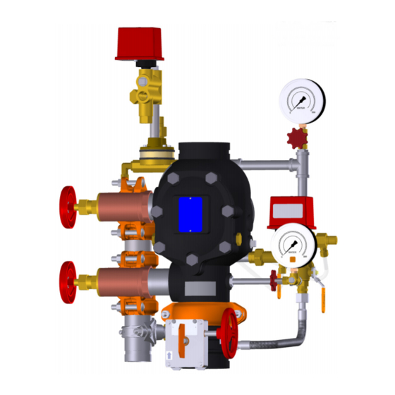
Series 769N FireLock NXT
Pneumatic (Dry Pilot) Release, Hydraulic (Wet Pilot) Release, and Electric Release Systems
• Series 769N FireLock NXT
current, applicable National Fire Protection Association (NFPA 13, 13D, 13R, etc.) standards, or equivalent standards, and in accordance
with applicable building and fire codes. These standards and codes contain important information regarding protection of systems from
freezing temperatures, corrosion, mechanical damage, etc.
• These installation instructions are intended for an experienced, trained installer. The installer shall understand the use of this product and
why it was specified for the particular application.
• The installer shall understand common industry safety standards and potential consequences of improper product installation.
Failure to follow installation requirements and local and national codes and standards could compromise system integrity or cause system
failure, resulting in death or serious personal injury and property damage.
REV_F
™
Deluge Valve
• Read and understand all instructions before attempting to install any Victaulic products.
• Always verify that the piping system has been completely depressurized and drained
immediately prior to installation, removal, adjustment, or maintenance of any Victaulic
products.
• Wear safety glasses, hardhat, and foot protection.
Failure to follow these instructions could result in death or serious personal injury and property
damage.
™
Deluge Valves shall be used only in fire protection systems that are designed and installed in accordance with
WARNING
I-769N.Deluge
KEEP THESE INSTRUCTIONS WITH THE
INSTALLED VALVE FOR FUTURE REFERENCE
Scan QR Code for Access to Videos
and Additional Publications
I-769N.Deluge
Advertisement
Table of Contents

Related Manuals for Victaulic 769N FireLock NXT Series


Summary of Contents for Victaulic 769N FireLock NXT Series
- Page 1 Additional Publications WARNING • Read and understand all instructions before attempting to install any Victaulic products. • Always verify that the piping system has been completely depressurized and drained immediately prior to installation, removal, adjustment, or maintenance of any Victaulic products.
- Page 2 Normal Operating Position Alarm Test Ball Valve of the Priming Manifold Water Supply Main Control Valve Open Closed Assembly Slow-Fill Ball Valve of the Victaulic AMTA Water Supply Main Drain Valve Closed Open (if applicable) Fast-Fill Ball Valve of the Victaulic AMTA...
- Page 3 Auto Drain Sleeve Auto Vent Sleeve of Series 776 Low-Pressure Ball Drip Actuator Plunger System Main Drain Valve Charge Line Ball Water Supply Valve Main Control Valve Water Supply Main Drain Valve Alarm Test Ball Valve Pneumatic (Dry Pilot) Release Trim Shown (Manual pull station not shown for clarity of components) REQUIRED WATER FLOW ALARM TEST Refer to NFPA 25, FM Datasheets, or any applicable local requirements to perform water flow alarm tests.
-
Page 4: Table Of Contents
Removing and Replacing the Clapper Seal....33 removal, adjustment, or maintenance of any Victaulic products. Removing and Replacing the Clapper Assembly....34 Failure to follow these instructions can cause product failure, Installing the Cover Plate Gasket and Cover Plate. -
Page 5: Important Installation Information
When an uninterrupted water flow alarm is required, Victaulic recommends the use of a low-pressure alarm installed on the charge line downstream of the priming manifold assembly. -
Page 6: Receiving The Shipment
™ Deluge Valve / Installation, Maintenance, and Testing Manual RECEIVING THE SHIPMENT Install the valve assembly into the riser with two Victaulic rigid couplings. Refer to the instructions, supplied with the coupling, NOTICE for complete installation requirements. SERIES 769N FIRELOCK NXT DELUGE VALVES SHALL BE INSTALLED ONLY IN THE •... -
Page 7: Trim Dimensions
I-769N.Deluge / Series 769N FireLock NXT ™ Deluge Valve / Installation, Maintenance, and Testing Manual TRIM DIMENSIONS A 4-INCH/114.3-MM VALVE WITH PNEUMATIC (DRY PILOT) RELEASE TRIM IS SHOWN BELOW 1 1/2 – 2-INCH/48.3 – 60.3-MM CONFIGURATIONS CONTAIN 3/4-INCH/19-MM DRAIN VALVES 2 1/2 –... -
Page 8: Trim Components - Exploded View Drawing
I-769N.Deluge / Series 769N FireLock NXT ™ Deluge Valve / Installation, Maintenance, and Testing Manual TRIM COMPONENTS – EXPLODED VIEW DRAWING Series 769N FireLock NXT Deluge Valve - Pneumatic (Dry Pilot) Release Trim Orange shaded areas identify components that are optional equipment. These components are standard when the VQR assembly is ordered. -
Page 9: Trim Components - Exploded View Drawing - Hydraulic (Wet Pilot) Release Trim
I-769N.Deluge / Series 769N FireLock NXT ™ Deluge Valve / Installation, Maintenance, and Testing Manual TRIM COMPONENTS – EXPLODED VIEW DRAWING Series 769N FireLock NXT Deluge Valve - Hydraulic (Wet Pilot) Release Trim Orange shaded areas identify components that are optional equipment. These components are standard when the VQR assembly is ordered. -
Page 10: Electric Release Trim
I-769N.Deluge / Series 769N FireLock NXT ™ Deluge Valve / Installation, Maintenance, and Testing Manual TRIM COMPONENTS – EXPLODED VIEW DRAWING Series 769N FireLock NXT Deluge Valve - Electric Release Trim Orange shaded areas identify components that are optional equipment. These components are standard when the VQR assembly is ordered. -
Page 11: Internal Valve Components - Section View And Exploded View Drawings
I-769N.Deluge / Series 769N FireLock NXT ™ Deluge Valve / Installation, Maintenance, and Testing Manual INTERNAL VALVE COMPONENTS – SECTION VIEW AND EXPLODED VIEW DRAWINGS Clapper Latch Diaphragm Assembly Clapper Seal Seat Exaggerated for Clarity Valve is shown in the “set” position The 1½-inch/48.3-mm and 2-inch/60.3-mm valve sizes contain washers under the heads of the cover plate bolts. -
Page 12: Air Supply Requirements
When a base- or riser-mounted air compressor supplies air to a Series 769N FireLock NXT Deluge Valve with dry pilot trim, it is not necessary to install the Victaulic Series 757 Regulated Air Maintenance Trim Assembly (AMTA). In this case, the air line of the compressor connects to the trim at the fitting where the Series 757 Regulated AMTA is installed normally (refer to the applicable trim drawing). -
Page 13: Wet Pilot Line Charts
I-769N.Deluge / Series 769N FireLock NXT ™ Deluge Valve / Installation, Maintenance, and Testing Manual WET PILOT LINE CHARTS Maximum allowable wet pilot line heights for specific equivalent lengths (heights are based on 1/2-inch/21.3-mm Schedule 40 pipe and a 1/2-inch/21.3-mm sprinkler) 1½... - Page 14 I-769N.Deluge / Series 769N FireLock NXT ™ Deluge Valve / Installation, Maintenance, and Testing Manual WET PILOT LINE CHARTS Maximum allowable wet pilot line heights for specific equivalent lengths (heights are based on 1/2-inch/21.3-mm Schedule 40 pipe and a 1/2-inch/21.3-mm sprinkler) 4-inch/114.3-mm Valve Size 300 psi 280 psi...
- Page 15 I-769N.Deluge / Series 769N FireLock NXT ™ Deluge Valve / Installation, Maintenance, and Testing Manual WET PILOT LINE CHARTS Maximum allowable wet pilot line heights for specific equivalent lengths (heights are based on 1/2-inch/21.3-mm Schedule 40 pipe and a 1/2-inch/21.3-mm sprinkler) 8-inch/219.1-mm Valve Size 225 psi 200 psi...
- Page 16 I-769N.Deluge / Series 769N FireLock NXT ™ Deluge Valve / Installation, Maintenance, and Testing Manual SECTION I • Initial System Setup I-769N.Deluge_16 REV_F...
-
Page 17: Initial System Setup
I-769N.Deluge / Series 769N FireLock NXT ™ Deluge Valve / Installation, Maintenance, and Testing Manual INITIAL SYSTEM SETUP FOR PNEUMATIC (DRY PILOT) RELEASE SYSTEMS: Step P5a: Charge the dry pilot release system with air by turning NOTICE on the compressor or by opening the fast-fill ball valve on the AMTA. - Page 18 Open the water supply main control valve fully. Closed Assembly Step 11: Slow-Fill Ball Valve of the Victaulic AMTA Open (if applicable) Confirm that all valves are in their normal operating positions (refer to Fast-Fill Ball Valve of the Victaulic AMTA the table to the right).
- Page 19 I-769N.Deluge / Series 769N FireLock NXT ™ Deluge Valve / Installation, Maintenance, and Testing Manual This page intentionally left blank REV_F I-769N.Deluge_19...
- Page 20 I-769N.Deluge / Series 769N FireLock NXT ™ Deluge Valve / Installation, Maintenance, and Testing Manual SECTION II • Resetting the System I-769N.Deluge_20 REV_F...
-
Page 21: Resetting The System
I-769N.Deluge / Series 769N FireLock NXT ™ Deluge Valve / Installation, Maintenance, and Testing Manual RESETTING THE SYSTEM Step 4: Close the system main drain valve. NOTICE Step 5: • Prior to resetting the system, the cover plate shall be removed Confirm that all system drains are shut and that the system is free to verify that the clapper is resting on the seat in the closed from leaks. - Page 22 I-769N.Deluge / Series 769N FireLock NXT ™ Deluge Valve / Installation, Maintenance, and Testing Manual SECTION III • Inspection/Testing Requirements WARNING • The building owner or their representative is responsible for maintaining the fire protection system in proper operating condition. •...
-
Page 23: Weekly External Inspection
Alarm Test Ball Valve of the Priming Manifold NOTICE Closed Assembly Slow-Fill Ball Valve of the Victaulic AMTA Open • If the deluge system is equipped with a low-pressure alarm, (if applicable) monthly inspections may be sufficient. Contact the local... - Page 24 I-769N.Deluge / Series 769N FireLock NXT ™ Deluge Valve / Installation, Maintenance, and Testing Manual SECTION IV • Required Main Drain Test • Required Water Flow Alarm Test • Required Water Level and Low- Air Alarm Tests • Required Partial Operational Trip Test •...
-
Page 25: Required Main Drain Test
Assembly Alarm Test Ball Valve of the Priming Manifold Closed CAUTION Assembly Slow-Fill Ball Valve of the Victaulic AMTA Open (if applicable) • Use caution to prevent opening the system main drain valve Fast-Fill Ball Valve of the Victaulic AMTA accidentally. -
Page 26: Required Water Flow Alarm Test
I-769N.Deluge / Series 769N FireLock NXT ™ Deluge Valve / Installation, Maintenance, and Testing Manual REQUIRED WATER FLOW ALARM TEST Open the water supply main drain valve fully to flush the water supply of any contaminants. Refer to NFPA 25, FM Datasheets, or any applicable local requirements Close the water supply main drain valve. -
Page 27: Required Water Level And Low-Air Alarm Tests
Closed FOR PNEUMATIC (DRY PILOT) RELEASE SYSTEMS: Assembly Close the slow-fill ball valve on the AMTA. Slow-Fill Ball Valve of the Victaulic AMTA Open (if applicable) Open the fast-fill ball valve on the AMTA. Bring the pressure back Fast-Fill Ball Valve of the Victaulic AMTA up to the normal system pressure. -
Page 28: Required Partial Operational Trip Test
Close the water supply main control valve fully. operation; however, this test does not confirm full system operation. Victaulic recommends performing the partial operational (trip) test 10. Close the remote system test valve (inspector’s test connection) or annually (at minimum). NOTE: The frequency of the partial operational the system main drain valve. -
Page 29: Required Full Operational Trip Test
Record the following: 6a. The time between opening the remote system test valve Victaulic recommends the full operational (trip) test every 3 years (at (inspector’s test connection) and operation of the deluge minimum). NOTE: The frequency of the full operational (trip) test shall... - Page 30 I-769N.Deluge / Series 769N FireLock NXT ™ Deluge Valve / Installation, Maintenance, and Testing Manual SECTION V • Required Internal Inspection WARNING • Depressurize and drain the piping system before attempting to remove the cover plate from the valve. • The building owner or their representative is responsible for maintaining the fire protection system in proper operating condition.
-
Page 31: Required Internal Inspection
15. While the clapper is rotated out of the valve body, pull the latch forward to inspect the diaphragm. If the diaphragm shows any signs of wear or damage, replace it with a new, Victaulic-supplied diaphragm. Refer to the “Removing and Replacing the Diaphragm”... - Page 32 I-769N.Deluge / Series 769N FireLock NXT ™ Deluge Valve / Installation, Maintenance, and Testing Manual SECTION VI • Removing and Replacing the Clapper Seal • Removing and Replacing the Clapper Assembly • Installing the Cover Plate Gasket and Cover Plate •...
-
Page 33: Removing And Replacing The Clapper Seal
Pry the clapper seal, along with the seal ring, out of the clapper. Inspect the clapper seal. If the clapper seal is torn or worn, replace it with a new, Victaulic-supplied clapper seal. If replacing the clapper seal assembly with a new assembly, skip to step 7. -
Page 34: Removing And Replacing The Clapper Assembly
I-769N.Deluge / Series 769N FireLock NXT ™ Deluge Valve / Installation, Maintenance, and Testing Manual REQUIRED SEAL ASSEMBLY BOLT/BOLT SEAL TORQUES Nominal Size Required Torque inches or mm inch-lbs/N•m 1 ½ 2 ½ 76.1 mm 165.1 mm Install the clapper seal into the clapper carefully. Verify that the seal ring snaps into the clapper completely. -
Page 35: Installing The Cover Plate Gasket And Cover Plate
Verify that the cover plate gasket is in good condition. If the gasket is torn or worn, replace it with a new, Victaulic-supplied gasket. Align the holes of the cover plate gasket with the holes in the cover plate. -
Page 36: Removing And Replacing The Diaphragm
I-769N.Deluge / Series 769N FireLock NXT ™ Deluge Valve / Installation, Maintenance, and Testing Manual REMOVING AND REPLACING THE DIAPHRAGM CAUTION Remove the system from service by following steps 1 – 10 of the • DO NOT over-tighten the cover plate bolts. “Required Internal Inspection”... -
Page 37: Cleaning The Cartridge In The Air And Priming Manifold Assemblies
Failure to follow this instruction could cause improper valve operation, resulting in property damage. Use only a new, Victaulic-supplied filter. Install the new filter onto the filter adapter, as shown above. Verify that the o-ring is positioned on the filter adapter, as shown above. - Page 38 I-769N.Deluge / Series 769N FireLock NXT ™ Deluge Valve / Installation, Maintenance, and Testing Manual SECTION VII • Troubleshooting I-769N.Deluge_38 REV_F...
-
Page 39: Troubleshooting
Actuator is pulled up, the screw does not stay set in the “UP” The Series 776 Low-Pressure Actuator has a broken seal. If the above procedure does not work, contact Victaulic. position. Water is leaking through the Series 776 Low-Pressure Actuator. - Page 40 For complete contact information, visit victaulic.com I-769N.Deluge 9241 REV F UPDATED 01/2019 Z000769ND0 VICTAULIC AND FIRELOCK NXT ARE REGISTERED TRADEMARKS OR TRADEMARKS OF VICTAULIC COMPANY AND/OR ITS AFFILIATED ENTITIES IN THE UNITED STATES AND/OR OTHER COUNTRIES. © 2019 VICTAULIC COMPANY. ALL RIGHTS RESERVED.
Need help?
Do you have a question about the 769N FireLock NXT Series and is the answer not in the manual?
Questions and answers