Victaulic FireLock 751 Series Installation, Maintenance, And Testing Manual
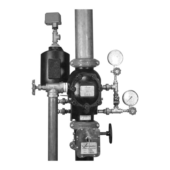
Alarm check valve
Hide thumbs
Also See for FireLock 751 Series:
- Manual (94 pages) ,
- Installation, maintenance, and testing manual (30 pages) ,
- Installation, maintenance, & testing manual (18 pages)
Table of Contents
Advertisement
Quick Links
Installation, Maintenance,
and Testing Manual
®
Series 751 FireLock
Alarm Check Valve
Hang these instructions on the
installed valve for easy future reference
WARNING
Failure to follow instructions and warnings can cause product failure, resulting in serious personal injury and/
or property damage.
• Read and understand all instructions before attempting to install any Victaulic piping products.
• Wear safety glasses, hardhat, and foot protection.
• Save this installation, maintenance, and testing manual for future reference.
If you need additional copies of any literature, or if you have any questions concerning the safe installation
and operation of this product, contact Victaulic, P.O. Box 31, Easton, PA 18044-0031, USA,
Telephone: 1-800 PICK VIC, e-mail: pickvic@victaulic.com.
R
Advertisement
Table of Contents

Related Manuals for Victaulic FireLock 751 Series


Summary of Contents for Victaulic FireLock 751 Series
- Page 1 Failure to follow instructions and warnings can cause product failure, resulting in serious personal injury and/ or property damage. • Read and understand all instructions before attempting to install any Victaulic piping products. • Wear safety glasses, hardhat, and foot protection.
-
Page 2: Table Of Contents
Series 751 FireLock® Alarm Check Valve TABLE OF CONTENTS HAZARD IDENTIFICATION Definitions for identifying the various hazard levels are provided below. Hazard Identification ........1 This safety alert symbol indicates important safety messages. -
Page 3: Installer Safety Instructions
General Read and understand all instructions and refer to the trim diagrams before proceeding with the installation, maintenance, and testing of this Victaulic Series 751 FireLock Alarm Check Valve. Inspect the shipment. Make sure all components are included with the shipment and that all necessary tools are available for installa- tion. -
Page 4: Introduction
Series 751 FireLock® Alarm Check Valve INTRODUCTION The following instructions are a guide for proper installation of Victaulic Series 751 Alarm Check Valves. These instructions involve pipe that is properly prepared and grooved in accordance with current Victaulic specifications. TRIM DIMENSIONS... -
Page 5: Exploded View Drawing - Trim Components
Series 751 FireLock® Alarm Check Valve EXPLODED VIEW DRAWING – TRIM COMPONENTS Series 751 Alarm Check Valve Grooved x Grooved (Optional Accessories Also Shown) SERIES 760 WATER MOTOR ALARM U L C LISTED ³⁄₄ Optional Pressure Switch To Water Motor Alarm or Optional Restrictor Optional Series 752V... -
Page 6: Exploded View Drawing - Trim Components (Canada Only)
Series 751 FireLock® Alarm Check Valve EXPLODED VIEW DRAWING – TRIM COMPONENTS (CANADA ONLY) Series 751 Alarm Check Valve for Use with Excess Pressure Pump Grooved x Grooved (Optional Accessories Also Shown) Pressure Switch From Excess Pressure Pump SERIES 760 WATER MOTOR ALARM U L C... -
Page 7: Exploded View Drawing - Internal Valve Components
Series 751 FireLock® Alarm Check Valve EXPLODED VIEW DRAWING – INTERNAL VALVE COMPONENTS 4 - 6" 1¹⁄₂ - 3 & 8" Clapper Alarm Outlet Seat Alarm Test Exaggerated for clarity BILL OF MATERIALS 1 Valve Body Clapper Spring 2 Clapper Spacers (Qty. -
Page 8: Series 751 Alarm Check Valve - Trim Assembly Drawing Numbers
Series 751 FireLock® Alarm Check Valve SERIES 751 ALARM CHECK VALVE – TRIM ASSEMBLY DRAWING NUMBERS VALVE SIZE VALVE SIZE Actual Outside Actual Outside Nominal Diameter Diameter Vertical Trim Horizontal Trim Nominal Diameter Diameter Vertical Trim Horizontal Trim inches (mm) inches (mm) Drawing Number Drawing Number... -
Page 9: Important Installation Information
When the Series 751 Alarm Check Valve is used with a water The Victaulic Series 751 Alarm Valve is UL Listed and FM Approved for motor alarm, it is recommended that the valve contain an uninterrupted,... -
Page 10: Placing The System In Service
Series 751 FireLock® Alarm Check Valve PLACING THE SYSTEM IN SERVICE Allow the system to fill with water completely. Allow water to flow from the remote system test valve (inspector’s test connection) and any auxiliary drains until all trapped air is removed from the system. After a steady flow of water is established and all air is released CAUTION from the system, close the remote system test valve (inspector’s test... -
Page 11: External Inspection
Notify the authority having jurisdiction, remote station alarm mon- • The Victaulic Series 751 Alarm Check Valve and trim must not be itors, and those in the affected area that the main drain test will be per- exposed to foreign material, corrosive environments, freezing con- formed. - Page 12 Series 751 FireLock® Alarm Check Valve System’s Main Drain Valve Open the system’s main drain valve completely. Open the alarm line ball valve. With the system’s main drain valve open completely, record the Confirm that all valves are in their normal operating positions water supply’s pressure as the residual pressure.
-
Page 13: Required Internal Inspection
Series 751 FireLock® Alarm Check Valve REQUIRED INTERNAL INSPECTION Inspect internal components every five years, as required by the current NFPA-25 code. The authority having jurisdiction in the area may require these inspections on a more frequent basis. Verify these requirements by contacting the authority having jurisdiction in the affected area. - Page 14 Series 751 FireLock® Alarm Check Valve Rotate the clapper out of the valve body. Inspect the clapper seal and seal-retaining ring. Wipe away any contaminants, dirt, and mineral deposits. Clean out any holes that are plugged in the valve-body seat ring.
-
Page 15: Maintenance
Series 751 FireLock® Alarm Check Valve MAINTENANCE The following steps instruct on how to remove and replace internal valve components. Care must be taken to avoid damage to parts. WARNING • Depressurize and drain the piping system before attempting to remove the cover plate from the alarm check valve. - Page 16 Pry the clapper seal, along with the seal ring, out of the clapper. Inspect the seal. If the clapper seal is torn or worn, replace it with a new, Victaulic-supplied clapper seal. If replacing the clapper seal assembly with a new assembly, skip to step 7 below.
- Page 17 Remove the solid clapper seal from the clapper. Inspect the seal. If the solid clapper seal is torn or worn, replace it with a new, Victaulic- supplied solid clapper seal.
-
Page 18: Removing And Replacing The Clapper Assembly (All Sizes)
Series 751 FireLock® Alarm Check Valve Removing and Replacing the Clapper Assembly (All Sizes) Place the new clapper assembly onto the valve-body seat ring. Make sure the holes in the clapper arms align with the holes in the valve body. Remove the clapper shaft-retaining plugs from the valve body. -
Page 19: Installing The Cover Plate Gasket And Cover Plate
Verify that the cover plate gasket is in good condition. If the gasket is torn or worn, replace it with a new, Victaulic-supplied gasket. Place the other spacer between the clapper and the valve body. - Page 20 Series 751 FireLock® Alarm Check Valve CAUTION • DO NOT over-tighten the cover bolts. Failure to follow this instruction could cause damage to the cover plate gasket, resulting in valve leakage. Torque all cover bolts in an even, crossing pattern. Refer to the “Required Cover Bolt Torque”...
-
Page 21: Troubleshooting - Series 751 Alarm Check Valve
Series 751 FireLock® Alarm Check Valve TROUBLESHOOTING – SERIES 751 ALARM CHECK VALVE Problem Possible Cause Solution The system water pressure gauge is fluctuating The check valve in the bypass line is installed Check the orientation of the bypass check valve. with the supply pressure backward. - Page 22 4901 Kesslersville Road • Easton, PA 18040 USA Phone: 610/559-3300 • Fax: 610/250-8817 e-mail: pickvic@victaulic.com VICTAULIC TOOL COMPANY VICTAULIC CONSTRUCTION PIPING SERVICES DIV. P.O. Box 31 • Easton, PA 18044-0031 1818 Vultee Street • Allentown, PA 18103 Phone: 1-888-VIC-TOOL • Fax: 610/923-3090 Phone: 610/559-3488 •...
Need help?
Do you have a question about the FireLock 751 Series and is the answer not in the manual?
Questions and answers