Victaulic FireLock 751 Series Installation, Maintenance, & Testing Manual
European alarm check valve stations
Hide thumbs
Also See for FireLock 751 Series:
- Manual (94 pages) ,
- Installation, maintenance, and testing manual (30 pages) ,
- Replacement instructions manual (8 pages)
Table of Contents
Advertisement
Quick Links
Installation,
Maintenance, & Testing Manual
WARNING
Failure to follow instructions and warnings could cause product failure, resulting in serious personal injury and/or property
damage.
• Read and understand all instructions before attempting to install, maintain, or test any Victaulic piping products.
• Wear safety glasses, hardhat, and foot protection.
If you need additional copies of any literature, or if you have any questions about the safe installation and operation of this
product, contact Victaulic Company of Europe, Prijkelstraat 36, 9810 Nazareth, Belgium, Phone: 32-9-381-1500.
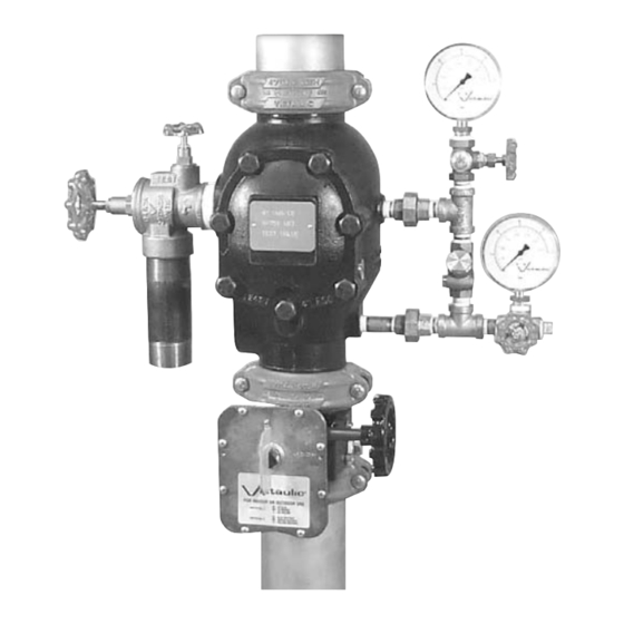
FireLock
Alarm Check Valve Stations
Hang these instructions on the
installed valve for easy future reference.
R
Series 751
European
®
VdS
0786
Advertisement
Table of Contents

Related Manuals for Victaulic FireLock 751 Series


Summary of Contents for Victaulic FireLock 751 Series
- Page 1 Failure to follow instructions and warnings could cause product failure, resulting in serious personal injury and/or property damage. • Read and understand all instructions before attempting to install, maintain, or test any Victaulic piping products. • Wear safety glasses, hardhat, and foot protection.
-
Page 2: Table Of Contents
® Series 751 FireLock European Alarm Check Valve Stations TABLE OF CONTENTS HAZARD IDENTIFICATION Definitions for identifying the various hazard levels are provided Hazard Identification ....... . 1 below. -
Page 3: Installer Safety Instructions
Victaulic Company of Europe, Prijkelstraat 36, 9810 Nazareth, Belgium, Phone: 32-9-381-1500. WARNING • Depressurize and drain the piping system before attempting to install, remove, or adjust any Victaulic piping products. Failure to follow this instruction could cause product failure, resulting in serious personal injury and/or property damage. -
Page 4: Introduction
European Alarm Check Valve Stations INTRODUCTION The following instructions are a guide for proper installation of Victaulic Series 751 Alarm Check Valves. These instructions involve pipe that is properly prepared and grooved in accordance with current Victaulic specifications. TRIM DIMENSIONS Dimensions –... -
Page 5: Exploded View Drawing - Trim Components
® Series 751 FireLock European Alarm Check Valve Stations EXPLODED VIEW DRAWING – TRIM COMPONENTS Series 751 FireLock™ European Alarm Check Valve Stations (Optional Accessories Also Shown) Grooved X Grooved SERIES 760 WATER MOTOR ALARM U L C LISTED ³⁄₄ Optional Retard Chamber... -
Page 6: Exploded View Drawing - Internal Valve Components
Remove all plastic caps and foam spacers from the valve. Series 751 Alarm Check Valves MUST be installed in the Install the Victaulic Series 751 Alarm Check Valve in ac- vertical position only. The arrow on the body must point upward, cordance with the applicable trim drawings. -
Page 7: Placing The System In Service
® Series 751 FireLock European Alarm Check Valve Stations PLACING THE SYSTEM IN SERVICE Allow the system to fill with water completely. Allow water to flow from the auxiliary drains to release all trapped air from the system. CAUTION When a steady flow of water occurs and all air is released from the system, close the auxiliary drains in the system. -
Page 8: External Inspection
• If you do not want to activate alarms, close the alarm line ball valve procedures. • The Victaulic Series 751 Alarm Check Valve and trim must not be exposed to foreign material, corrosive environments, freezing conditions, contami- nated water supplies, or any other condition that could impair proper sys- tem operation. -
Page 9: Water Flow Alarm Test
® Series 751 FireLock European Alarm Check Valve Stations Water Flow Alarm Test The authority having jurisdiction in your area may require the wa- ter flow alarm test on a more frequent basis. Verify these require- ments by contacting the authority having jurisdiction in your area. - Page 10 ® Series 751 FireLock European Alarm Check Valve Stations Push in the plunger on the restricted orifice/alarm line drain (7), as shown above. Verify that no water is flowing from the restricted orifice/ alarm line drain (7). Notify the authority having jurisdiction, remote station alarm monitors, and those in the affected area that the valve is back in service.
-
Page 11: Required Internal Inspection
WARNING damage. • Depressurize and drain the piping system before attempting to install, remove, or adjust any Victaulic piping products. Failure to follow this instruction could cause serious personal injury and/or property damage. CAUTION • Any activities that require taking the valve out of service may eliminate the fire protection provided. - Page 12 ® Series 751 FireLock European Alarm Check Valve Stations Rotate the clapper out of the valve body. Inspect the clap- per seal and seal-retaining ring. Wipe away any contaminants, dirt, and mineral deposits. Clean any holes in the valve body seat ring that are plugged.
-
Page 13: Maintenance
WARNING • Depressurize and drain the piping system before attempting to install, remove, or adjust any Victaulic piping products. Failure to follow this instruction could cause serious personal injury and/or property dam- age. Remove the seal-retaining ring. This seal-retaining ring will need to be re-installed in later steps. -
Page 14: Removing And Replacing Clapper Assembly
Place the seal-retaining ring onto the solid seal, as shown above. CAUTION Remove one clapper shaft retaining bushing from the • Use only Victaulic-supplied replacement seal assembly bolt/ bolt seal when valve body. reassembling the clapper. Failure to follow this instruction could cause improper sealing, resulting in valve leakage and/or property damage. -
Page 15: Installing Cover Plate Gasket And Cover Plate
Installing Cover Plate Gasket and Cover Plate Verify that the cover plate gasket is in good condition. If the gasket is torn or worn, replace it with a new, Victaulic-sup- plied gasket. Place the new clapper assembly onto the valve body seat ring so that the holes in the clapper arms align with the holes in the valve body, as shown above. - Page 16 ® Series 751 FireLock European Alarm Check Valve Stations Torque all cover bolts in an even, crossing pattern. Refer to the “Cover Bolt Torque Requirements” chart on this page for the required torque values. DO NOT over-tighten the cover bolts. Cover Bolt Torque Requirements Valve Torque...
-
Page 17: Troubleshooting - Series 751 Alarm Check Valve
® Series 751 FireLock European Alarm Check Valve Stations TROUBLESHOOTING – SERIES 751 ALARM CHECK VALVE Problem Possible Cause Solution The system water pressure gauge is fluctuating with the supply The check valve in the bypass line is installed backward. Check the orientation of the bypass check valve. - Page 18 4901 Kesslersville Road • Easton, PA 18040 USA Phone: 610/559-3300 • Fax: 610/250-8817 e-mail: pickvic@victaulic.com VICTAULIC TOOL COMPANY VICTAULIC CONSTRUCTION PIPING SERVICES DIV. P.O. Box 31 • Easton, PA 18044-0031 1818 Vultee Street • Allentown, PA 18103 Phone: 610/559-3300 • Fax: 610/923-3090 Phone: 610/559-3488 •...
Need help?
Do you have a question about the FireLock 751 Series and is the answer not in the manual?
Questions and answers