Victaulic 751 FireLock Series Installation, Maintenance, And Testing Manual
European alarm check valve stations
Hide thumbs
Also See for 751 FireLock Series:
- Manual (94 pages) ,
- Installation, maintenance, and testing manual (30 pages) ,
- Installation, maintenance, & testing manual (18 pages)
Table of Contents
Advertisement
Quick Links
INSTALLATION, MAINTENANCE, AND TESTING MANUAL
Series 751 FireLock
• Read and understand all instructions before attempting to install, remove, adjust, or perform maintenance on any Victaulic piping products.
• Depressurize and drain piping systems before attempting to install, remove, adjust, or perform maintenance on any Victaulic piping
products.
• Wear safety glasses, hardhat, and foot protection.
• Save this installation, maintenance, and testing manual for future reference.
Failure to follow instructions and warnings could cause system failure, resulting in death or serious personal injury and property damage.
REV_F
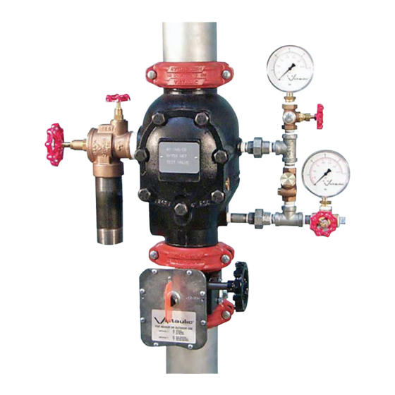
European Alarm Check Valve Stations
™
INSTALLED VALVE FOR EASY FUTURE REFERENCE
WARNING
I-751.VDS
HANG THESE INSTRUCTIONS ON THE
I-751.VDS
Advertisement
Table of Contents

Related Manuals for Victaulic 751 FireLock Series


Summary of Contents for Victaulic 751 FireLock Series
- Page 1 WARNING • Read and understand all instructions before attempting to install, remove, adjust, or perform maintenance on any Victaulic piping products. • Depressurize and drain piping systems before attempting to install, remove, adjust, or perform maintenance on any Victaulic piping products.
-
Page 2: Table Of Contents
I-751.VDS / Series 751 FireLock ™ European Alarm Check Valve Stations / Installation, Maintenance, and Testing Manual TABLE OF CONTENTS HAZARD IDENTIFICATION Hazard Identification . . . . . . . . . . . . . . . . . . . . . . . . . . . . . . . . . . . . . . 1 Definitions for identifying the various hazard levels are provided below . -
Page 3: Installer Safety Instructions
Notify the authority having jurisdiction. Always notify the author- diagrams before proceeding with the installation, maintenance, ity having jurisdiction before performing any maintenance that and testing of this Victaulic Series 751 FireLock European Alarm eliminates the fire protection provided by the system . Check Valve Station. -
Page 4: Introduction
European Alarm Check Valve Stations / Installation, Maintenance, and Testing Manual INTRODUCTION The following instructions are a guide for proper installation of Victaulic Series 751 FireLock European Alarm Check Valve Stations . These instructions involve pipe that is prepared and grooved properly in accordance with Victaulic specifications . -
Page 5: Exploded View Drawing - Trim Components
I-751.VDS / Series 751 FireLock ™ European Alarm Check Valve Stations / Installation, Maintenance, and Testing Manual EXPLODED VIEW DRAWING – TRIM COMPONENTS SERIES 751 FIRELOCK EUROPEAN ALARM CHECK VALVE STATIONS (OPTIONAL ACCESSORIES ALSO SHOWN) To Water Motor Alarm or Optional Series 752V Retard Vent Kit Optional Series 752V... -
Page 6: Exploded View Drawing - Internal Valve Components
I-751.VDS / Series 751 FireLock ™ European Alarm Check Valve Stations / Installation, Maintenance, and Testing Manual EXPLODED VIEW DRAWING – INTERNAL VALVE COMPONENTS Clapper Alarm Outlet Seat Exaggerated for clarity Bill of Materials Valve Body Bolt Seal Clapper Shaft Retaining Bushing (Qty. 2) Seal-Assembly Bolt Clapper Shaft Cover Plate Gasket... -
Page 7: Important Installation Information
The Victaulic Series 752 VdS Retarding Chamber Assembly should CAUTION be installed in variable pressure applications . NOTE: Victaulic pro- vides specific trim drawings for installations that involve a Series • Make sure no foreign material gets into the valve body, pipe 752 VdS Retarding Chamber Assembly . -
Page 8: Placing The System In Service
I-751.VDS / Series 751 FireLock ™ European Alarm Check Valve Stations / Installation, Maintenance, and Testing Manual PLACING THE SYSTEM IN SERVICE CAUTION • The Series 751 FireLock Alarm Check Valve and supply piping must be protected from freezing temperatures and mechanical damage. - Page 9 I-751.VDS / Series 751 FireLock ™ European Alarm Check Valve Stations / Installation, Maintenance, and Testing Manual 10 . Open the water supply main control valve (3) fully . CAUTION • The alarm line ball valve must be open to allow alarms to acti- vate.
-
Page 10: External Inspection
• Depressurize and drain the piping system before attempting to Confirm that the alarm check valve and trim are located in an area install, remove, adjust, or maintain any Victaulic products. that is not subject to freezing temperatures . Failure to follow these instructions could cause system failure, If the valve is installed in a variable pressure system, confirm that resulting in death, serious personal injury, and property damage. -
Page 11: Required System Tests
Close the alarm line ball valve (11) . • Depressurize and drain the piping system before attempting to install, remove, adjust, or maintain any Victaulic products. Failure to follow these instructions could cause system failure, resulting in death, serious personal injury, and property damage. - Page 12 I-751.VDS / Series 751 FireLock ™ European Alarm Check Valve Stations / Installation, Maintenance, and Testing Manual CAUTION • The alarm line ball valve must be open to allow alarms to acti- vate. Failure to follow this instruction will prevent alarms from activating during a fire condition, resulting in personal injury and/or property damage.
-
Page 13: Water Flow Alarm Test
I-751.VDS / Series 751 FireLock ™ European Alarm Check Valve Stations / Installation, Maintenance, and Testing Manual WATER FLOW ALARM TEST Perform the water flow alarm test on a frequency required by national standards . In addition, the authority having jurisdiction in the area may require these tests on a more frequent basis . -
Page 14: Required Internal Inspection
I-751.VDS / Series 751 FireLock ™ European Alarm Check Valve Stations / Installation, Maintenance, and Testing Manual REQUIRED INTERNAL INSPECTION Internal components should be inspected every five years or as required by national standards . The authority having jurisdiction in the area may require these inspections on a more frequent basis . -
Page 15: Maintenance
I-751.VDS / Series 751 FireLock ™ European Alarm Check Valve Stations / Installation, Maintenance, and Testing Manual MAINTENANCE CAUTION The following sections instruct on how to remove and replace internal valve components . Care must be taken to avoid damage to parts during •... - Page 16 . Make sure the sealing surface area is clean, dry, and free of foreign material . If the clapper shows any signs of damage, replace it with a new, Victaulic-supplied clapper . Install the solid clapper seal into the clapper . Make sure the seal- ing lip is pointing upward .
-
Page 17: Removing And Replacing The Clapper Seal
Pry the clapper seal, along with the seal ring, out of the clapper . Inspect the clapper seal . If the clapper seal is torn or worn, replace it with a new, Victaulic-supplied clapper seal . If replacing the clap- per seal assembly with a new assembly, skip to step 7 . - Page 18 . If the clapper shows any signs of damage, System in Service" section . replace it with a new, Victaulic-supplied clapper . Install the clapper seal into the clapper carefully . Make sure the seal ring snaps into the clapper completely .
-
Page 19: Removing And Replacing The Clapper Assembly (All Sizes)
I-751.VDS / Series 751 FireLock ™ European Alarm Check Valve Stations / Installation, Maintenance, and Testing Manual REMOVING AND REPLACING THE CLAPPER ASSEMBLY (ALL SIZES) Perform steps 1 – 4 of the "Required Internal Inspection" section . Verify that the clapper seal is installed properly in the clapper by referring to the applicable “Removing and Replacing the Clapper Seal”... -
Page 20: Installing The Cover Plate Gasket And Cover Plate
Verify that the cover plate gasket is in good condition . If the gasket is torn or worn, replace it with a new, Victaulic-supplied gasket . Align the cover plate/cover plate gasket to the valve . Make sure the clapper spring’s arms are rotated to their installed position . -
Page 21: Troubleshooting - Series 751 Firelock European
I-751.VDS / Series 751 FireLock ™ European Alarm Check Valve Stations / Installation, Maintenance, and Testing Manual TROUBLESHOOTING – SERIES 751 FIRELOCK EUROPEAN ALARM CHECK VALVE STATIONS PROBLEM POSSIBLE CAUSE SOLUTION The system water pressure gauge is fluctuating with the supply The check valve in the bypass line is installed backward. - Page 22 For complete contact information, visit victaulic.com I-751.VDS 3580 REV F UPDATED 08/2017 ZI00751VDS VICTAULIC AND FIRELOCK ARE REGISTERED TRADEMARKS OR TRADEMARKS OF VICTAULIC COMPANY AND/OR ITS AFFILIATED ENTITIES IN THE UNITED STATES AND/OR OTHER COUNTRIES. © 2015 VICTAULIC COMPANY. ALL RIGHTS RESERVED.
Need help?
Do you have a question about the 751 FireLock Series and is the answer not in the manual?
Questions and answers