Table of Contents
Advertisement
Advertisement
Table of Contents

Subscribe to Our Youtube Channel
Related Manuals for HIKVISION DS-2CD6825G0


Summary of Contents for HIKVISION DS-2CD6825G0
-
Page 1: Installation And Configuration Guide For Dual-Lens People Counting Camera
Installation and Configuration Guide for Dual-lens People Counting Camera... -
Page 2: Table Of Contents
Content ..........1 Installation and Configuration Guide for Dual-lens People Counting Camera ......................... 3 Chapter 1. Brief introduction ....................... 4 Chapter 2. Installation specification 2.1 Focal length and counting width ..................4 2.2 Accessaries .......................... 7 2.3 Installation steps ........................7 2.4 Counting configuration ...................... -
Page 3: Chapter 1. Brief Introduction
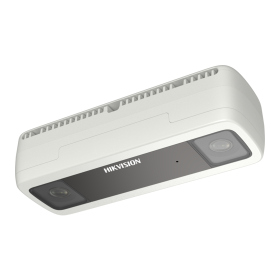
Chapter 1. Brief introduction DS-2CD6825G0/C-I(V)(S), dual-lens camera, based on the binocular stereo vision technology, adopting 3D head detection and 3D tracking, can obtain accurate real-time trajectory of all moving objects within the monitoring scope, analyze the trajectory data and achieve high-precision people counting. -
Page 4: Chapter 2. Installation Specification
Chapter 2. Installation specification 2.1 Focal length and counting width The counting width depends on the installation height. The recommended installation height for dual-lens camera is less than 4.0m (13.1ft). The specific corresponding relation shown below: Focal length Installation height Max. - Page 5 Focal length Installation height Max. counting width Max. counting depth (m/ft) (m/ft) (m/ft) (mm/ft) 3.7/12.1 5.12/16.8 2.88/9.4 3.8/12.5 5.38/17.7 3.02/9.9 3.9/12.8 5.63/18.5 3.17/10.4 4.0/13 5.89/19.3 3.31/10.9 4.1/13.5 6.14/20.1 3.46/11.4 4.2/13.8 6.4/21 3.6/11.8 4.3/14.1 6.66/21.9 3.74/12.3 4.4/14.4 6.91/22.7 3.89/12.8 4.5/14.8 7.17/23.5 4.03/13.2 4.6/15.1 5.5/18...
- Page 6 Focal length Installation height Max. counting width Max. counting depth (m/ft) (m/ft) (m/ft) (mm/ft) 5.8/19 7.78/25.5 4.36/14.3 5.9/19.4 7.97/26.1 4.47/14.7 6/19.7 8.16/26.8 4.57/15...
-
Page 7: Accessaries
2.2 Accessaries Dual-lens Camera Drill Template Screws Quick guide 2.3 Installation steps Please pay great attention to the mounting position. Inappropriate mounting position may cause loss of accuracy. The recommended mounting position is shown below:... - Page 8 Horizontal sketch map of mounting position Vertical sketch map of mounting position Effect picture after installation Keep “HIKVISION” logo in the same direction as the “Front” arrow, see picture below:...
- Page 9 “Front” arrow and “HIKVISION” logo Make sure camera mounted vertically above the passenger flow(90°vertical by the ground), see picture below: Passenger flow(perpendicular to the door) For some scenarios where there are multiple cameras, mount the cameras according to two rules.
- Page 10 Rule two: If there is no turnstile, at first, mount the cameras in one line, and make sure the cameras have the same focal length. Then, keep a proper distance between each camera according to the overlap (see the yellow area below) of the adjacent two cameras’ counting width.
- Page 11 Passenger flow in vertical up-and-down direction (right) 2) Passageway width should be within camera’s counting width 3) Avoid obstacles such glass door, shield door and turnstile that block the camera. For Each divided passageway, mount one camera right above 4) The camera should be mounted as close as possible to the passageway without obstacle.
-
Page 12: Counting Configuration
Too far away from the door/Obstacle below camera Recommended installation 2.4 Counting configuration Configuration for single camera Step 1. Select VCA Resource. It is necessary to select the VCA source as People Counting Mode. Step 2. Rule Configuration: 1) Enter 【VCA】-【People Counting】, check “Enable People Counting”。 2) Select the calibration mode: Manual and Auto are selectable. - Page 13 appear in the image. The red area is for counting. To increase the success rate of the manual calibration, make sure the lens height is the true value in vertical direction between the lens and the ground. Auto Calibration Mode: It will generate the lens height and a green calibration area automatically. The calibration area is used for calibrating the height from the ground to lens.
- Page 14 Notice: (1) If auto calibration fails, switch to [Manual] and input the measured “Height”, then click [Calibration]. (2) The detection area should be flat, avoid uneven area like steps or slope. Step 3. NOTE: The rule frame should be within red counting frame.
- Page 15 Step 4. Draw detection line (the yellow line as shown in the below picture) or detection region. Detection Line: the yellow line should be within the blue detection region. Detection Region: Draw A and B region. Make sure the two areas don’t overlap. If the target enters from A region to B region, then it is counted as the entering number;...
- Page 16 Step 5. Save it after finishing the configuration. Set the Arming schedule and linkage method.
-
Page 17: Configuration For Multiple Cameras
Configuration for multiple cameras Step 1. Do configuration for each camera following the steps above Step 2. Move each camera’s detection line and connect the ends of adjacent lines. Some objects could be placed on the image border for reference. See picture below: Configuration of each detection line Parameter description Reverse Counting Alarm:... - Page 18 Shield Region: If you don’t want to count people of the specific area, you can draw the area as shield region. Data Uploading: 1) Enter 【VCA】-【People Counting】-【Data Uploading】 2) If you want to upload the real-time data to the platform, select real-time Upload Data as “ON’’. 3) If you want to adjust the statistic cycle manually, set data statistics data as required.
- Page 19 Overlay & Capture: 1) OSD Overlay: It supports display the real-time counting information in the live view image. Enter, Leave, Enter/Leave and None are optional. 2) Counting Type: Adult, Child and All are optional. 3) Daily Reset Time/Rest OSD: To reset the counter, you can set up a daily reset time. Or you can reset the OSD counter manually by click Manual Reset.
- Page 20 Advanced Parameter: 1) Height Filter: Enable the function and set a height value. Persons and objects shorter than the set value are not counted as a valid target. Also this camera support counting Children. 2) Target Detection Type/Algorithm Validity: There are four type of target detection: Detect based on the tracking algorithm only; Depth map only;...
-
Page 21: Chapter 3. Application Scenario
4) Counting Status: It displays the current status of the camera. There are three types optional: Counting, Stopped, Pause counting. You can click Refresh button to refresh the status. Counting: Count normally. Stopped: Disable people counting function. Pause counting: The scene is too dark. 5) Clear Storage Data: To clear stored data on camera, you can click the Clear button. - Page 22 Mounting position and configuration for subway...
Need help?
Do you have a question about the DS-2CD6825G0 and is the answer not in the manual?
Questions and answers