Vega VEGAFLEX 81 Operating Instructions Manual
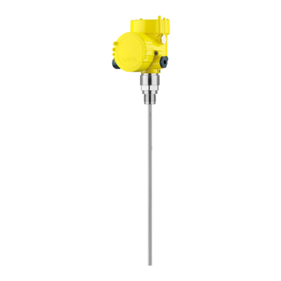
Tdr sensor for continuous level and interface measurement of liquids
Hide thumbs
Also See for VEGAFLEX 81:
- Operating instructions manual (100 pages) ,
- Quick setup manual (24 pages) ,
- Mounting instructions (20 pages)

Related Manuals for Vega VEGAFLEX 81


Summary of Contents for Vega VEGAFLEX 81
-
Page 1: Operating Instructions
Operating Instructions TDR sensor for continuous level and interface measurement of liquids VEGAFLEX 81 Modbus and Levelmaster protocol Document ID: 41828... -
Page 2: Table Of Contents
DD adjustment programs ..........50 Communicator 375, 475 ........... 50 Diagnostics and service Maintenance ..............51 Diagnosis memory ............51 Status messages .............. 52 Rectify faults ..............56 Exchanging the electronics module ........59 VEGAFLEX 81 • Modbus and Levelmaster protocol... - Page 3 Please note the Ex-specific safety information for installation and op- eration in Ex areas. These safety instructions are part of the operating instructions manual and come with the Ex-approved instruments. Editing status: 2012-11-06 VEGAFLEX 81 • Modbus and Levelmaster protocol...
-
Page 4: About This Document
Action This arrow indicates a single action. Sequence Numbers set in front indicate successive steps in a procedure. Battery disposal This symbol indicates special information about the disposal of bat- teries and accumulators. VEGAFLEX 81 • Modbus and Levelmaster protocol... -
Page 5: For Your Safety
During work on and with the device the required personal protective equipment must always be worn. Appropriate use VEGAFLEX 81 is a sensor for continuous level measurement. You can find detailed information on the application range in chapter "Product description". -
Page 6: Namur Recommendations
The environment management system is certified according to DIN EN ISO 14001. Please help us fulfil this obligation by observing the environmental instructions in this manual: • Chapter "Packaging, transport and storage" • Chapter "Disposal" VEGAFLEX 81 • Modbus and Levelmaster protocol... -
Page 7: Product Description
Operating instructions at the time of shipment (PDF) • Order-specific sensor data for an electronics exchange (XML) • Test certificate "Measuring Accuracy" (PDF) For this purpose, move to www.vega.com and "VEGA Tools". The instrument contains two different electronics in its housing cham- Electronics design bers: •... -
Page 8: Principle Of Operation
– CE declarations of conformity – if necessary, further certificates Principle of operation Application area The VEGAFLEX 81 is a level sensor with cable or rod probe for continuous level or interface measurement, suitable for applications in liquids. Functional principle -... - Page 9 The dielectric constant of the upper medium must be known (input required). Min. dielectric constant: rod version 1.6. You can find a list with the dielectric constants on our home page: www.vega.com • The composition of the upper medium must be stable, no varying products or mixtures •...
-
Page 10: Packaging, Transport And Storage
USB interface of a PC. For parameter adjustment of these instruments, an adjustment software such as PACTware with VEGA-DTM is required. You can find further information in the operating instructions "Interface adapter VEGACONNECT" (Document-ID 32628). VEGAFLEX 81 • Modbus and Levelmaster protocol... - Page 11 You can hence use the indicating and adjustment module in a tem- perature range of -40 … 70 °C. You can find further information in the operating instructions "Indicat- ing and adjustment module with heating" (Document-ID 31708). VEGAFLEX 81 • Modbus and Levelmaster protocol...
- Page 12 You can find further information in the operating instructions manual "Bypass tube VEGAPASS 81". If you mount the VEGAFLEX 81 in a bypass tube or standpipe, you Spacer have to avoid contact to the bypass tube by using a spacer at the probe end.
-
Page 13: Mounting
Instructions for installation Installation position Mount VEGAFLEX 81 in such a way that the distance to vessel instal- lations or to the vessel wall is at least 300 mm (12 in). In non-metallic vessels, the distance to the vessel wall should be at least 500 mm (19.7 in). - Page 14 If this is not possible, use short sockets with small diameter. Higher sockets or sockets with a bigger diameter can generally be used. They simply increase the upper blocking distance. Check if this is relevant for your measurement. VEGAFLEX 81 • Modbus and Levelmaster protocol...
- Page 15 By doing this, you avoid damage to the electronics through inductive coupling. Inflowing medium Do not mount the instruments in or above the filling stream. Make sure that you detect the product surface, not the inflowing product. VEGAFLEX 81 • Modbus and Levelmaster protocol...
- Page 16 If durability is no problem, then we recommend the use of metal standpipes. When the VEGAFLEX 81 is used in standpipes or bypass tubes, contact with the tube wall must be avoided. We recommend for this purpose a cable probe with centering weight.
- Page 17 Rod extensions In case of difficult installation conditions, the probe can be also mounted laterally. For this purpose, adapt the rod with rod extensions or bow-shaped segments. VEGAFLEX 81 • Modbus and Levelmaster protocol...
- Page 18 Make sure that the rod of the probe is at least 300 mm (11.811 in) away from the vessel wall You can find further information in the supplementary instructions of the rod extension. VEGAFLEX 81 • Modbus and Levelmaster protocol...
-
Page 19: Connecting To Power Supply And Bus System
Connecting Connection technology The voltage supply and signal output are connected via the spring- loaded terminals in the housing. VEGAFLEX 81 • Modbus and Levelmaster protocol... - Page 20 8. Connect the screen to the internal ground terminal, connect the outer ground terminal to potential equalisation 9. Tighten the compression nut of the cable entry. The seal ring must completely encircle the cable VEGAFLEX 81 • Modbus and Levelmaster protocol...
-
Page 21: Wiring Plan
Fig. 12: Electronics compartment, double chamber housing Internal connection to the connection compartment For indicating and adjustment module or interface adapter Information: The connection of an external indicating and adjustment unit is not possible with this double chamber housing. VEGAFLEX 81 • Modbus and Levelmaster protocol... -
Page 22: Switch-On Phase
Modbus-Signal D1 Function ground with installa- tion according to CSA Switch-on phase After VEGAFLEX 81 is connected to the bus system, the instrument carries out a self-test for approx. 30 seconds. The following steps are carried out: • Internal check of the electronics •... -
Page 23: Set Up With The Indicating And Adjustment Module
Fig. 14: Insertion of the indicating and adjustment module with single chamber housing Note: If you intend to retrofit the instrument with an indicating and adjust- ment module for continuous measured value indication, a higher cover with an inspection glass is required. VEGAFLEX 81 • Modbus and Levelmaster protocol... -
Page 24: Adjustment System
Through the parameter adjustment the instrument is adapted to the application conditions. The parameter adjustment is carried out via an adjustment menu. Main menu The main menu is divided into five sections with the following func- tions: VEGAFLEX 81 • Modbus and Levelmaster protocol... - Page 25 You can enter names with max. 19 characters. The character set comprises: • Capital letters from A … Z • Numbers from 0 … 9 • Special characters + - / _ blanks VEGAFLEX 81 • Modbus and Levelmaster protocol...
- Page 26 You have the possibility to choose the demonstration mode.This mode is suitable for test and demonstration purposes. In this mode, the sensor ignores the logic parameters of the application and reacts immediately to each change. VEGAFLEX 81 • Modbus and Levelmaster protocol...
- Page 27 You can directly enter the dielectric constant of the upper medium or have it determined by the instrument. You have to enter the meas- ured distance to the interface. VEGAFLEX 81 • Modbus and Levelmaster protocol...
- Page 28 The distance refers tot he sensor reference plane (seal surface of the process fitting). Setup/Max. adjustment - This menu item is only available if you have selected interface meas- Interface urement under the menu item "Application". VEGAFLEX 81 • Modbus and Levelmaster protocol...
- Page 29 0 … 999 s in this menu item. If you have selected interface measurement under the menu item "Application", you can adjust the damping for the level and the inter- face separately. VEGAFLEX 81 • Modbus and Levelmaster protocol...
- Page 30 Setup/Scaling - Level 2 Since the scaling is very comprehensive, the scaling of the level value was divided into two menu items. VEGAFLEX 81 • Modbus and Levelmaster protocol...
- Page 31 In menu item "Interface 2" you define the scaling format on the display and the scaling of the interface measured value for 0 % and 100 %. Setup/Current output - In menu item"Current output, size" you determine which measured Size value the current output refers to. VEGAFLEX 81 • Modbus and Levelmaster protocol...
- Page 32 A change of the values is not possible in the indicating and adjust- ment module. To change these values, you have to use the adjust- ment software PACTware. Setup/False signal sup- The following circumstances cause interfering reflections and can pression influence the measurement: VEGAFLEX 81 • Modbus and Levelmaster protocol...
- Page 33 Display/Menu language This menu item enables the setting of the requested national lan- guage. In the delivery status, the sensor is set to the ordered national lan- guage. VEGAFLEX 81 • Modbus and Levelmaster protocol...
- Page 34 "Setup/Application", then the peak values of the interface meas- urement are displayed in addition to the peak values of the level measurement. In another window you can carry out a reset of the two peak values separately. VEGAFLEX 81 • Modbus and Levelmaster protocol...
- Page 35 Diagnostics/Echo curve The menu item "Echo curve" shows the signal strength of the echoes over the measuring range in V. The signal strength enables an evalua- tion of the quality of the measurement. VEGAFLEX 81 • Modbus and Levelmaster protocol...
- Page 36 With this menu item you can only start or stop the storing process. With the adjustment software PACTware and the PC the high-reso- lution echo curve can be displayed and used later on to assess the quality of the measurement. VEGAFLEX 81 • Modbus and Levelmaster protocol...
- Page 37 With a reset, certain parameter adjustments carried out by the user - Reset are reset. The following reset functions are available: Delivery status: Restoring the parameter settings at the time of ship- ment from the factory incl. the order-specific settings. A created false VEGAFLEX 81 • Modbus and Levelmaster protocol...
- Page 38 The instrument settings are copied with this function. The following Additional adjustments/ Copy instrument settings functions are available: • read from sensor: Read data from sensor and store into the indi- cating and adjustment module VEGAFLEX 81 • Modbus and Levelmaster protocol...
- Page 39 Multidrop mode. In the mode "Fix current output" up to 63 sensors can be operated on one two-wire cable (Multidrop operation). An address between 0 and 63 must be assigned to each sensor. VEGAFLEX 81 • Modbus and Levelmaster protocol...
- Page 40 PC. Info/Sensor character- In this menu item, the features of the sensor such as approval, pro- istics cess fitting, seal, measuring range, electronics, housing and others are displayed. VEGAFLEX 81 • Modbus and Levelmaster protocol...
-
Page 41: Saving The Parameter Adjustment Data
If it is necessary to exchange a sensor, the indicating and adjustment module is inserted into the replacement instrument and the data are likewise written into the sensor via the menu item "Copy sensor data". VEGAFLEX 81 • Modbus and Levelmaster protocol... -
Page 42: Setting Up Sensor And Modbus Interface With Pactware
To the Modbus electron- The connection of the PC to the Modbus electronics is carried out via a USB cable. Scope of the parameter adjustment: • Sensor electronics • Modbus electronics Fig. 17: Connecting the PC via USB to the Modbus electronics 1 USB cable to the PC VEGAFLEX 81 • Modbus and Levelmaster protocol... -
Page 43: Parameter Adjustment With Pactware
Further setup steps are described in the operating instructions manu- al "DTM Collection/PACTware" attached to each DTM Collection and which can also be downloaded from the Internet. Detailed descrip- tions are available in the online help of PACTware and the DTMs. VEGAFLEX 81 • Modbus and Levelmaster protocol... -
Page 44: Set Up With The Quick Setup
The standard version is available as a download under www.vega. com/downloads and "Software". The full version is available on CD from the agency serving you. - Page 45 2 Extended adjustment Maintenance Quick setup With quick setup you can carry out the parameter adjustment of VEGAFLEX 81 for your application in just a few simple steps. The assistant-driven adjustment includes the basic settings for simple, reliable setup and commissioning. Information: If the function is inactive, then possibly no instrument is connected.
- Page 46 Interface measurement: If you select "Interface", the instrument needs more information, such as the distance to the interface, the dielectric constant of the upper medium or whether or not there is a superim- posed gas phase. VEGAFLEX 81 • Modbus and Levelmaster protocol...
- Page 47 If you have a non-linear vessel, you can select here the respective linearization curve. • Linear • Spherical tank • Horizontal cylindrical tank • User programmable • Venturi, trapezoidal weir, rectangular weir VEGAFLEX 81 • Modbus and Levelmaster protocol...
- Page 48 DTM Collection is required. This procedure can last several minutes. Store echo curve of the setup in the sensor? Did you terminate the first setup of the instrument? In such case, we recommend storing the current signal conditions in the device for later instrument tests and diagnostics. VEGAFLEX 81 • Modbus and Levelmaster protocol...
-
Page 49: Saving The Parameter Adjustment Data
PIN is entered again. Saving the parameter adjustment data We recommend documenting or saving the parameter adjustment data via PACTware. That way the data are available for multiple use or service purposes. VEGAFLEX 81 • Modbus and Levelmaster protocol... -
Page 50: Set Up With Other Systems
Device descriptions as Enhanced Device Description (EDD) are available for DD adjustment programs such as, for example, AMS™ and PDM. The files can be downloaded at www.vega.com/downloads under "Software". Communicator 375, 475 Device descriptions for the instrument are available as DD or EDD for parameter adjustment with the Field Communicator 375 or 475. -
Page 51: Diagnostics And Service
Changes in the measure- ment conditions during operation or buildup on the sensor can thus be recognized. The echo curve of the setup is stored via: • PC with PACTware/DTM • Control system with EDD VEGAFLEX 81 • Modbus and Levelmaster protocol... -
Page 52: Status Messages
Maintenance: Due to external influences, the instrument function is limited. The measurement is affected, but the measured value is still valid. Plan in maintenance for the instrument because a failure is expected in the near future (e.g. due to buildup). VEGAFLEX 81 • Modbus and Levelmaster protocol... - Page 53 4-wire power supply unit F125 – Temperature of the elec- – Check ambient temperature tronics in the non-specified – Isolate electronics Unpermissi- section – Use instrument with higher ble electronics temperature range temperature VEGAFLEX 81 • Modbus and Levelmaster protocol...
- Page 54 Text mes- sage S600 – Temperature of the pro- – Check ambient temperature cessing electronics in the – Isolate electronics Unpermissi- non-specified section – Use instrument with higher ble electronics temperature range temperature VEGAFLEX 81 • Modbus and Levelmaster protocol...
- Page 55 – Clean or exchange process – Process component or component or probe probe contaminated or defective M504 – Hardware defect – Exchanging the electronics – Send instrument for repair Error on an device inter- face VEGAFLEX 81 • Modbus and Levelmaster protocol...
-
Page 56: Rectify Faults
Error Cause Rectification 4 … 20 mA signal – Level fluctua- – Set damping according to the not stable tions instrument via the indicating and adjustment module or PACTware/ VEGAFLEX 81 • Modbus and Levelmaster protocol... - Page 57 – Wrong linearization curve – Adapt linearization curve time – Running time error (small – Repeat setup measurement error close to 100 %/serious error close to 0 %) VEGAFLEX 81 • Modbus and Levelmaster protocol...
- Page 58 – Stored false signals in this – Delete false signal memory mains reproducible position are larger than the – Carry out a new false signal in one position during level echo suppression emptying time VEGAFLEX 81 • Modbus and Levelmaster protocol...
-
Page 59: Exchanging The Electronics Module
24 hour service hotline Should these measures not be successful, please call in urgent cases the VEGA service hotline under the phone no. +49 1805 858550. The hotline is also available outside the normal working hours on seven days a week around the clock. -
Page 60: How To Proceed In Case Of Repair
Attach the completed form and, if need be, also a safety data sheet outside on the packaging • Please contact for the return shipment the agency serving you. You can find the agency on our home page www.vega.com. VEGAFLEX 81 • Modbus and Levelmaster protocol... -
Page 61: Dismounting
Pass the instrument directly on to a spe- cialised recycling company and do not use the municipal collecting points. These may be used only for privately used products according to the WEEE directive. VEGAFLEX 81 • Modbus and Levelmaster protocol... -
Page 62: Supplement
Ʋ Pipe thread, cylindrical (ISO 228 T1) G¾, G1 A, G1½ according to DIN 3852-A Ʋ American pipe thread, conical ¾ NPT, 1 NPT, 1½ NPT (ASME B1.20.1) Ʋ Flanges e.g. DIN from DN 25, ANSI from 1" Weight VEGAFLEX 81 • Modbus and Levelmaster protocol... - Page 63 10 Nm (7.376 lbf ft) Ʋ Aluminium/Stainless steel housing max. 50 Nm (36.88 lbf ft) Input variable Measured variable Level of liquids Min. dielectric figure of the medium Ʋ Cable probes ε ≥ 1.6 VEGAFLEX 81 • Modbus and Levelmaster protocol...
- Page 64 (+12.5 … +15.4 psig) Installation reference conditions Ʋ Min. distance to installations > 500 mm (19.69 in) Ʋ Vessel metallic, ø 1 m (3.281 ft), centric installation, process fitting flush with the vessel ceiling VEGAFLEX 81 • Modbus and Levelmaster protocol...
- Page 65 Depending on the installation conditions, there can be deviations which can be rectified with an adaptation of the adjustment or a change of the measured value offset in the DTM service mode The dead bands can be optimizes by a false signal suppression. VEGAFLEX 81 • Modbus and Levelmaster protocol...
- Page 66 ") -15 mm (-0.591 " 0,15 m 0,3 m 0,05 m (5.906 " (11.811 ") (1.969 ") 0,08 m (3.15 ") Fig. 35: Deviation VEGAFLEX 81 in cable version ø 2 mm (0.079 in), in oil Dead band - no measurement possible in this area Probe length VEGAFLEX 81 • Modbus and Levelmaster protocol...
- Page 67 Time span after a sudden measuring distance change by max. 0.5 m in liquid applications, max 2 m with bulk solids applications, until the output signal has taken for the first time 90 % of the final value (IEC 61298-2). VEGAFLEX 81 • Modbus and Levelmaster protocol...
- Page 68 Fig. 38: Ambient temperature - process temperature, version with temperature adapter Ambient temperature Process temperature (depending on the seal material) Maximum permissible temperature - standard Limited temperature range - plastic housing and stainless steel housing, electropolished Vibration resistance VEGAFLEX 81 • Modbus and Levelmaster protocol...
- Page 69 IP 20 Ʋ mounted into the sensor without cover IP 40 Materials Ʋ Housing Ʋ Inspection window Polyester foil Integrated clock Date format Day.Month.Year Time format 12 h/24 h Time zone Ex factory VEGAFLEX 81 • Modbus and Levelmaster protocol...
-
Page 70: Basics Modbus
Instruments with approvals can have different technical data depending on the version. For that reason the associated approval documents of these instruments must be carefully noted. They are part of the delivery or can be downloaded under www.vega.com and "VEGA Tools" as well as under "Downloads" and "Approvals". - Page 71 Fig. 39: Bus architecture Modbus Connection resistor Bus participant Voltage supply Protocol description The VEGAFLEX 81 is suitable for connection to the following RTUs with Modbus RTU or ASCII protocol. Protocol ABB Totalflow Modbus RTU, ASCII Bristol ControlWaveMicro Modbus RTU, ASCII Fisher ROC...
-
Page 72: Modbus Register
(4 bytes) according to IEEE 754 are transmitted with individually selectable order of the data bytes (byte transmission order). This "Byte transmission order" is determined in the parameter "Format Code". Hence the RTU knows the registers of the VEGAFLEX 81 which must be contacted for the variables and status information. - Page 73 Quarternary Variable in Byte-Reihenfolge DCBA (Lit- tle Endian) Status 2200 DWord See Register 100 2202 DWord Primary Variable in Byte Order BACD (Middle Endian) 2204 DWord Secondary Variable in Byte Order BACD (Middle En- dian) VEGAFLEX 81 • Modbus and Levelmaster protocol...
-
Page 74: Modbus Rtu Commands
1 Byte 0x03 Start Address 2 Bytes Register Value N*2 Bytes Data FC4 Read Input Register With this command, any number (1-127) of input registers can be read out. The start register, from VEGAFLEX 81 • Modbus and Levelmaster protocol... - Page 75 Code/Data Function Code 1 Byte 0x08 Sub Function Code 2 Bytes Data N*2 Bytes Data Response: Parameter Length Code/Data Function Code 1 Byte 0x08 Sub Function Code 2 Bytes Data N*2 Bytes Data VEGAFLEX 81 • Modbus and Levelmaster protocol...
- Page 76 Response: Parameter Length Code/Data Function Code 1 Byte 0x11 Byte Number 1 Byte Slave ID 1 Byte Run Indicator Status 1 Byte FC43 Sub 14, Read Device Identification With this function code, the Device Identification can be queried. VEGAFLEX 81 • Modbus and Levelmaster protocol...
-
Page 77: Levelmaster Commands
List of Object value 1 Byte Depending on the Object ID 11.5 Levelmaster commands The VEGAFLEX 81 is also suitable for connection to the following RTUs with Levelmaster protocol. The Levelmaster protocol is often called "Siemens" "Tank protocol". Protocol ABB Totalflow... - Page 78 6 characters ASCII UuuNnn Assign Unit Number Request: Parameter Length Code/Data Assign Unit Number 6 characters ASCII UuuNnn Response: Parameter Length Code/Data Assign Unit Number 6 characters ASCII UuuNOK uu = new Address VEGAFLEX 81 • Modbus and Levelmaster protocol...
- Page 79 = 127 ms Response: Parameter Length Code/Data Set Receive to Transmit Delay 6 characters ASCII UuuROK Report Number of Floats Request: Parameter Length Code/Data Set Receive to Transmit Delay 4 characters ASCII UuuF VEGAFLEX 81 • Modbus and Levelmaster protocol...
-
Page 80: Error Codes
= milliseconds (50 bis 250), default = 127 ms Error codes Error Code Name EE-Error Error While Storing Data in EEPROM FR-Error Erorr in Frame (to short, to long, wrong data) LV-Error Value out of limits VEGAFLEX 81 • Modbus and Levelmaster protocol... -
Page 81: Configuration Of Typical Modbus Hosts
Input Register Base Number The basic number of the input registers is always added to the input register address of VEGAFLEX Address 1300 must hence be entered as register address for RTU Fisher ROC 809. VEGAFLEX 81 • Modbus and Levelmaster protocol... - Page 82 The basic number of the input registers is always added to the input register address of VEGAFLEX Address 1303 must hence be entered as register address for 1302 for RTU ABB Total Flow. VEGAFLEX 81 • Modbus and Levelmaster protocol...
- Page 83 The basic number of the input registers is always added to the input register address of VEGAFLEX Address 1300 must hence be entered as register address for 1300 for RTU Thermo Electron Auto- pilot. VEGAFLEX 81 • Modbus and Levelmaster protocol...
- Page 84 The basic number of the input registers is always added to the input register address of VEGAFLEX Address 1303 must hence be entered as register address for 1302 for RTU Bristol ControlWave Micro. VEGAFLEX 81 • Modbus and Levelmaster protocol...
-
Page 85: Dimensions
Address 31303 must hence be entered as register address for 1302 for RTU ScadaPack. 11.7 Dimensions The following dimensional drawings represent only an extract of all possible versions. Detailed dimensional drawings can be downloaded at www.vega.com/downloads under "Drawings". VEGAFLEX 81 • Modbus and Levelmaster protocol... - Page 86 11 Supplement Housing ~ 87 mm (3.43") ø 84 mm (3.31") M16x1,5 M20x1,5/ ½ NPT Fig. 45: Dimensions housing - with integrated indicating and adjustment module the housing is 9 mm/0.35 in higher VEGAFLEX 81 • Modbus and Levelmaster protocol...
- Page 87 11 Supplement VEGAFLEX 81, cable version with gravity weight SW 36 (1.42") (G¾, ¾ NPT) SW 41 (1.61") (G1, 1 NPT) SW 46 (1.81") (G1½, 1½ NPT) G¾, ¾ NPT, G1, 1 NPT, G1½, 1½ NPT ø 4 mm (0.16") ø...
- Page 88 11 Supplement VEGAFLEX 81, cable version with centering weight SW 36 (1.42") (G¾, ¾ NPT) SW 41 (1.61") (G1, 1 NPT) SW 46 (1.81") (G1½, 1½ NPT) G¾, ¾ NPT, G1, 1 NPT, G1½, 1½ NPT ø 4 mm (0.16") ø...
- Page 89 SW 41 (1.61") (G1, 1 NPT) SW 46 (1.81") (G1½, 1½ NPT) G¾, ¾ NPT, G1, 1 NPT, G1½, 1½ NPT G1½, 1½ NPT ø 8 mm ø 12¨mm (0.32") (0.47") Fig. 48: VEGAFLEX 81, threaded version Sensor length, see chapter "Technical data" Rod version ø 8 mm (0.315 in) Rod version ø 12 mm (0.472 in) VEGAFLEX 81 • Modbus and Levelmaster protocol...
- Page 90 Линии продукции фирмы ВЕГА защищаются по всему миру правами на интеллектуальную собственность. Дальнейшую информацию смотрите на сайте VEGA系列产品在全球享有知识产权保护。 进一步信息请参见网站< >。 11.9 Trademark All the brands as well as trade and company names used are property of their lawful proprietor/ originator. VEGAFLEX 81 • Modbus and Levelmaster protocol...
- Page 91 Product type 26 Event memory 51 Read out info 40 Repair 60 Factory calibration date 40 Replacement parts False signal suppression 32 – Bypass 12 Fault rectification 56 – Electronics module 11 Functional principle 8 VEGAFLEX 81 • Modbus and Levelmaster protocol...
- Page 92 – Spacer 12 Reset 37 Scaling measured value 30, 31 Sensor characteristics 40 Sensor status 34 Service hotline 59 Simulation 36 Special parameters 39 Status messages 52 Storage 10 Type label 7 Units 26 VEGAFLEX 81 • Modbus and Levelmaster protocol...
- Page 93 Notes VEGAFLEX 81 • Modbus and Levelmaster protocol...
- Page 94 Notes VEGAFLEX 81 • Modbus and Levelmaster protocol...
- Page 95 Notes VEGAFLEX 81 • Modbus and Levelmaster protocol...
- Page 96 Subject to change without prior notice © VEGA Grieshaber KG, Schiltach/Germany 2012 VEGA Grieshaber KG Phone +49 7836 50-0 Am Hohenstein 113...
Need help?
Do you have a question about the VEGAFLEX 81 and is the answer not in the manual?
Questions and answers
Error Codes E036 showing problem