Vega VEGAFLEX 81 Quick Setup Manual
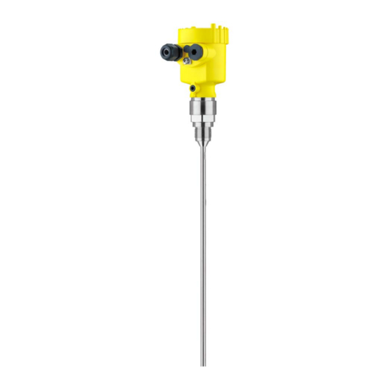
Tdr sensor for continuous level and interface measurement of liquids
Hide thumbs
Also See for VEGAFLEX 81:
- Operating instructions manual (100 pages) ,
- Quick setup manual (24 pages) ,
- Mounting instructions (20 pages)

Related Manuals for Vega VEGAFLEX 81


Summary of Contents for Vega VEGAFLEX 81
-
Page 1: Quick Setup Guide
Quick setup guide TDR sensor for continuous level and interface measurement of liquids VEGAFLEX 81 Foundation Fieldbus Rod and cable probe Document ID: 47589... -
Page 2: Table Of Contents
You can find further information in the corresponding, comprehensive operating instructions. This manual is available on the supplied DVD or in the download area under "www.vega.com". Operating instructions VEGAFLEX 81 - Foundation Fieldbus - Rod and cable probe: Document-ID 44218 Editing status of the quick setup guide: 2014-03-17... -
Page 3: For Your Safety
During work on and with the device the required personal protective equipment must always be worn. Appropriate use VEGAFLEX 81 is a sensor for continuous level measurement. You can find detailed information about the area of application in chapter "Product description". Operational reliability is ensured only if the instrument is properly used according to the specifications in the operating instructions manual as well as possible supplementary instructions. -
Page 4: Namur Recommendations
That is why we have introduced an environment management system with the goal of continuously improving company environmental pro- tection. The environment management system is certified according to DIN EN ISO 14001. Please help us fulfill this obligation by observing the environmental instructions in this manual: • Chapter "Packaging, transport and storage" • Chapter "Disposal" VEGAFLEX 81 • Foundation Fieldbus... -
Page 5: Product Description
Test certificate (PDF) - optional Go to www.vega.com, "VEGA Tools" and "Instrument search". Enter the serial number. Alternatively, you can access the data via your smartphone: • Download the smartphone app "VEGA Tools" from the "Apple App Store" or the "Google Play Store" VEGAFLEX 81 • Foundation Fieldbus... - Page 6 2 Product description • Scan the Data Matrix code on the type label of the instrument or • Enter the serial number manually in the app VEGAFLEX 81 • Foundation Fieldbus...
-
Page 7: Mounting
Mounting instructions Installation position Mount VEGAFLEX 81 in such a way that the distance to vessel instal- lations or to the vessel wall is at least 300 mm (12 in). In non-metallic vessels, the distance to the vessel wall should be at least 500 mm (19.7 in). - Page 8 Higher sockets or sockets with a bigger diameter can generally be used. They can, however, increase the upper blocking distance (dead band). Check if this is relevant for your measurement. In such cases, always carry out a false signal suppression after instal- lation. You can find further information under "Setup procedure". VEGAFLEX 81 • Foundation Fieldbus...
- Page 9 3 Mounting _ < DN40 ... DN150 _ < > DN150 ... DN200 Fig. 4: Mounting socket When welding the socket, make sure that the socket is flush with the vessel top. Fig. 5: Socket must be installed flush Unfavourable installation 2 Socket flush - optimum installation VEGAFLEX 81 • Foundation Fieldbus...
-
Page 10: Connecting To Power Supply
3. Loosen compression nut of the cable entry gland 4. Remove approx. 10 cm (4 in) of the cable mantle, strip approx. 1 cm (0.4 in) of insulation from the ends of the individual wires 5. Insert the cable into the sensor through the cable entry Fig. 6: Connection steps 5 and 6 - Single chamber housing VEGAFLEX 81 • Foundation Fieldbus... -
Page 11: Wiring Plan, Single Chamber Housing
9. Tighten the compression nut of the cable entry gland. The seal ring must completely encircle the cable 10. Reinsert the display and adjustment module, if one was installed 11. Screw the housing cover back on The electrical connection is finished. Wiring plan, single chamber housing The following illustration applies to the non-Ex, Ex-ia and Ex-d ver- sion. VEGAFLEX 81 • Foundation Fieldbus... -
Page 12: Wiring Plan, Double Chamber Housing
Wiring plan, double chamber housing The following illustrations apply to the non-Ex as well as to the Ex-ia version. Terminal compartment 6 7 8 Fig. 9: Terminal compartment, double chamber housing Voltage supply, signal output 2 For display and adjustment module or interface adapter 3 For external display and adjustment unit 4 Ground terminal for connection of the cable screen Information: The use of an external display and adjustment unit and a display and adjustment module in parallel in the connection compartment is not supported. VEGAFLEX 81 • Foundation Fieldbus... -
Page 13: Set Up With The Display And Adjustment Module
3. Screw housing cover with inspection window tightly back on Removal is carried out in reverse order. The display and adjustment module is powered by the sensor, an ad- ditional connection is not necessary. Fig. 10: Installing the display and adjustment module in the electronics compart- ment of the single chamber housing VEGAFLEX 81 • Foundation Fieldbus... -
Page 14: Parameter Adjustment - Quick Setup
In this menu item, you can select the application. You can choose between level measurement and interface measurement. You can also choose between measurement in a vessel or in a bypass or standpipe. Level measurement Medium - dielectric constant In this menu item, you can define the type of medium (product). VEGAFLEX 81 • Foundation Fieldbus... - Page 15 Min. adjustment - Interface Carry out the min. adjustment for the interface. To do this, enter the percentage value and the suitable distance value in m for the empty vessel. VEGAFLEX 81 • Foundation Fieldbus...
- Page 16 All interfering signals in this section are detected by the sensor and stored. The instrument carries out an automatic false signal suppression as soon as the probe is uncovered. The false signal suppression is always updated. VEGAFLEX 81 • Foundation Fieldbus...
-
Page 17: Supplement
Ʋ Non-Ex instrument 9 … 32 V DC Ʋ Ex-ia instrument - Power supply 9 … 17.5 V DC FISCO model Ʋ Ex-ia instrument - Power supply 9 … 24 V DC ENTITY model Ʋ Ex-d instrument 14 … 32 V DC Power supply by/max. number of sensors Ʋ Fieldbus max. 32 (max. 10 with Ex) VEGAFLEX 81 • Foundation Fieldbus... - Page 18 Notes VEGAFLEX 81 • Foundation Fieldbus...
- Page 19 Notes VEGAFLEX 81 • Foundation Fieldbus...
-
Page 20: Information
Subject to change without prior notice © VEGA Grieshaber KG, Schiltach/Germany 2014 VEGA Grieshaber KG Phone +49 7836 50-0 Am Hohenstein 113...
Need help?
Do you have a question about the VEGAFLEX 81 and is the answer not in the manual?
Questions and answers