Graco PD44 Setup And Operation
Control box
Hide thumbs
Also See for PD44:
- Operation & maintenance manual (42 pages) ,
- Operations & parts list (42 pages) ,
- Instructions manual (36 pages)
Table of Contents
Advertisement
Quick Links
Setup - Operation
PD44
Control Box
Meter, mix and dispense system for precise two-component micro-dispensing of sealants
and adhesives. Not for use in explosive atmospheres.
Important Safety Instructions
Read all warnings and instructions in this
manual. Save these instructions.
See page 3 for model information, including maximum
working pressure and approvals.
Micrometer PD44 and LRT PD44 Control Box shown
313877G
EN
Advertisement
Table of Contents

Related Manuals for Graco PD44


Summary of Contents for Graco PD44
- Page 1 Not for use in explosive atmospheres. Important Safety Instructions Read all warnings and instructions in this manual. Save these instructions. See page 3 for model information, including maximum working pressure and approvals. Micrometer PD44 and LRT PD44 Control Box shown...
-
Page 2: Table Of Contents
Grounding ....... . 9 Graco Information ......48 Setup . -
Page 3: Related Manuals
Related Manuals Related Manuals PD44 Manuals Part Description 313876 PD44 Dispense Valve Operation - Parts Feed System Manuals 306565 Air-Driven, Stainless Steel Agitators 307043 ® Monark Air Motor 308116 Severe-Duty, UHMWPE/PTFE or PTFE Packed Stainless Steel Pumps 308167 Low Volume Air Regulators... -
Page 4: Warnings
Warnings Warnings The following warnings are for the setup, use, grounding, maintenance, and repair of this equipment. The exclama- tion point symbol alerts you to a general warning and the hazard symbol refers to procedure-specific risk. Refer back to these warnings. Additional, product-specific warnings may be found throughout the body of this manual where applicable. - Page 5 Warnings WARNING PRESSURIZED EQUIPMENT HAZARD Fluid from the gun/dispense valve, leaks, or ruptured components can splash in the eyes or on skin and cause serious injury. • Follow Pressure Relief Procedure in this manual, when you stop spraying and before cleaning, checking, or servicing equipment.
-
Page 6: Component Identification
Power Input Air Cylinder Extend Connection Start Options Connection Air Cylinder Retract Connection Custom I/O Air Pressure Regulator A Tank Level Controls Connection Air Pressure Gauge B Tank Level Controls Connection . 1: Micrometer and LRT PD44 Control Box 313877G... - Page 7 BEFORE CONNECTING POWER Key: Emergency Stop Start Options Connection Control Power Switch A Tank Level Controls Connection Touch Panel B Tank Level Controls Connection Alarm Speaker Dispense Valve I/O Connection Power Input Motor Connection . 2: Motor Driven PD44 Control Box 313877G...
-
Page 8: Pd44 Dispense Valve
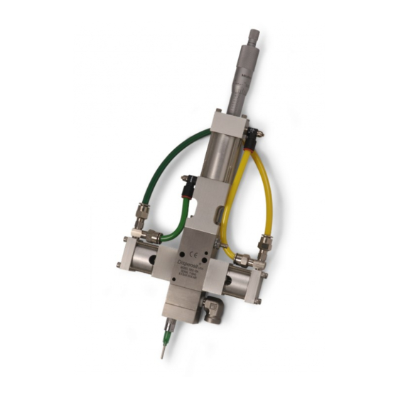
Component Identification PD44 Dispense Valve See PD44 Operation manual 313876 for detailed dis- pense valve component identification and instructions. . 3: PD44 Micrometer Dispense Valve 313877G... -
Page 9: Grounding
Grounding Grounding This product must be grounded. In the event of an elec- trical short circuit, grounding reduces the risk of electric shock by providing an escape wire for the electric cur- rent. Grounding plug units: this product is equipped with a cord having a grounding wire with an appropriate grounding plug. -
Page 10: Setup
Setup Setup 3. Connect Dispense Valve I/O, and Start Options Micrometer and LRT PD44 Only logic cables. If level controls are installed, connect Level Controls logic cables. NOTICE Feed system and main logic control system must use separate air supplies. -
Page 11: Motor Driven Pd44 Only
Setup Motor Driven PD44 Only 1. Connect Dispense Valve I/O, Start Options, and Motor logic cables. If level controls are installed, connect Level Controls logic cables. NOTICE Feed system and main logic control system must use separate air supplies. AUDIO ALARM... -
Page 12: Startup
Startup Startup NOTE: See HMI Operation starting on page 14 for detailed HMI instructions. 1. Press the Control Power On button. 2. On Micrometer and LRT PD44s, navigate to the ® Posidot Control screen. On Motor Driven PD44s, navigate to the Metering Valve Control screen. -
Page 13: Dispensing Operation
Dispensing Operation Dispensing Operation Retract Piston NOTE: See HMI Operation on page 14 for detailed HMI instructions. 1. On Micrometer and LRT PD44s, navigate to the Posidot Control screen. The foot switch, the “Start” button, and the optional Cus- On Motor Driven PD44s, navigate to the Metering tomer Start Signal can be used to initiate shots. -
Page 14: Hmi Operation
HMI Operation HMI Operation Screen Navigation Diagrams Micrometer PD44 Main Screen Status Purge Timer Level 1 Control Level 2 Control Posidot Control LRT PD44 Main Screen Posidot Control Shot Size/Flow Rate Level 1 Control Level 2 Control Purge Timer Status... - Page 15 HMI Operation Motor Driven PD44 Main Screen Metering Valve Control Shot Size/Flow Rate Level 1 Control Level 2 Control Purge Timer Status Motor Status Motor Error Codes Supervisor Supervisor Help 313877G...
-
Page 16: Main Screen
Status screen. The Password and Error Code buttons On all screens that it is shown, the Error Code button are only on the Motor Driven PD44 screens. resets the error seen in the error string (shown as “<0000000000”) and the error code number (shown as Password (Motor Driven PD44 only) “<000”). -
Page 17: Posidot Control Screen (Micrometer Pd44 And Lrt Pd44 Only)
(Micrometer PD44 and LRT PD44 only) NOTE: A “1” indicates that the button is in the “ON” position. A “0” indicates that the button is in the “OFF” position. LRT PD44 Posidot Control screen shown Start button Continuous Mode When the Start button is pressed, the machine starts the The machine continually cycles the pumps when the cycle for the selected Pump Mode. -
Page 18: Metering Valve Control Screen (Motor Driven Pd44 Only)
NOTE: A “1” indicates that the button is in the “ON” posi- tion. A “0” indicates that the button is in the “OFF” posi- tion. NOTE: The Error Code button is shown on every screen on the Motor Driven PD44. See the Main screen for defi- nition. Start button Extend Mode... - Page 19 HMI Operation DV Valve Mode This mode actuates an optional dispense valve. OPEN In this mode, the dispense valve is held in the open position, allowing material to pass through. AUTO In this mode, the dispsense valve opens automatically whenever the pump is cycled. CLOSE In this mode, the dispense valve is held closed.
-
Page 20: Shot Size Screen (Lrt Pd44 Only)
HMI Operation Shot Size Screen (LRT PD44 only) NOTE: This section describes the Shot Size screen for the LRT PD44 only. See page 21 for the Motor Driven PD44 Shot Size screen. Select Shot Size button NOTICE The Select Shot Size button allows the operator to... -
Page 21: Shot Size Screen (Motor Driven Pd44 Only)
HMI Operation Shot Size Screen (Motor Driven PD44 Only) NOTE: This section describes the Shot Size screen for the Motor Driven PD44 only. See page 20 for the LRT PD44 Shot Size screen. Shot Size (percent), Flow Rate (mm/sec) NOTICE... -
Page 22: Level 1 Control Screen
HMI Operation Level 1 Control Screen NOTE: The Error Code button is shown on every screen on the Motor Driven PD44. See the Main screen for defi- nition, page 16. NOTE: If ‘A Tank Status’ and ‘B Tank Status’ both dis- play 'Levels Not Active' then the level control feature is not installed on this machine. -
Page 23: Level 2 Control Screen
A “0” indicates that the button is in the “OFF” posi- tion. NOTE: The Error Code button is shown on every screen on the Motor Driven PD44. See the Main screen for defi- nition, page 16. NOTE: In the Level 1 Control Screen, if ‘A Tank Status’... - Page 24 HMI Operation Shutdown Timer button/indicator NOTE: For example, if 15 is entered, the Fill Timer set- ting is 1.5 seconds. NOTE: If the level control option has not been pur- chased the Shutdown Timer button is disabled. 3. Press the button.
-
Page 25: Purge Timer Screen
HMI Operation Purge Timer Screen NOTE: The Error Code button is shown on every screen on the Motor Driven PD44. See the Main screen for defi- nition, page 16. NOTE: On the Micrometer PD44, the “Purge Timer screen” is named the “Timer/Counter Screen.”... - Page 26 Purge Shot Size % field. 10 min X 10 cc 100 cc*min Number of Strokes During Purge button/indicator = 3.76 min (LRT and Motor Driven PD44 only) 2 X 13.3 cc 26.6 cc This displays the number of strokes used during the purge shot.
- Page 27 HMI Operation Amount Per Stroke % (LRT and Motor Driven PD44 only) This displays the percent of the stroke used during a shot. For example, if the shot size is set at 150%, Number of Strokes During Purge displays “2” and Amount Per Stroke % displays “75”.
-
Page 28: Status Screen
A “0” indicates that the button is in the “OFF” posi- tion. NOTE: The Error Code button is shown on every screen on the Motor Driven PD44. See the Main screen for defi- nition, page 16. Micrometer PD44 and LRT PD44 Status Screen Shown... - Page 29 “0” the switch is deactivated. See component identification section in dispense valve manual. See Related Manuals on page 3. PLC Program (Micrometer and LRT PD44 only) This gives the currently installed PLC program version and revision level. HMI Program (Micrometer and LRT PD44 only) This gives the currently installed HMI program version and revision level.
-
Page 30: Motor Status Screen (Motor Driven Pd44 Only)
A “0” indicates that the button is in the “OFF” posi- tion. NOTE: The Error Code button is shown on every screen on the Motor Driven PD44. See the Main screen for defi- nition, page 16. To navigate to the Motor Status screen, press the Lower Switch (Lower Over Limit Switch, Retract) “Motor Status”... - Page 31 HMI Operation Shot Mode Step # This gives the current step in the shot mode program. This is used for troubleshooting. Reload Mode Step # This gives the current step in the reload mode program. This is used for troubleshooting. Oper.
-
Page 32: Motor Error Codes Screen (Motor Driven Pd44 Only)
HMI Operation Motor Error Codes Screen (Motor Driven PD44 Only) These screens give descriptions of the motor error codes. 313877G... -
Page 33: Supervisor Screen (Lrt Pd44 Only)
HMI Operation Supervisor Screen (LRT PD44 Only) NOTE: This section describes the Supervisor screen for the LRT PD44 only. See page 34 for the Motor Driven PD44 Supervisor screen. Pump Reload Shot Size Offset Button Pump Reload sets a transducer point where the The Shot Size Offset button sets the transducer point machine will reload. -
Page 34: Supervisor Screen (Motor Driven Pd44 Only)
Supervisor Screen (Motor Driven PD44 Only) NOTE: This section describes the Supervisor screen for the Motor Driven PD44 only. See page 34 for the LRT PD44 Shot Size screen. NOTE: A “1” indicates that the button is in the “ON” position. A “0” indicates that the button is in the “OFF” position. -
Page 35: Supervisor Help Screen (Motor Driven Pd44 Only)
HMI Operation Supervisor Help Screen (Motor Driven PD44 Only) This screen describes the various reload and shot options in the Supervisor screen. To get to the Setup Help screen, press the “Help” button on the Supervisor screen. 313877G... -
Page 36: Calibration Screen (Lrt Pd44 Only)
HMI Operation Calibration Screen (LRT PD44 Only) Calibrate Mode button Transducer Position in % When this button is selected machine calibration starts. This shows the transducer position in percent of stroke. Extend Pumps button To calibrate the pumps, perform the following steps. - Page 37 HMI Operation Calibration Screen Help This screen describes the calibration procedure. 313877G...
-
Page 38: Pressure Relief Procedure
Pressure Relief Procedure Pressure Relief Procedure 1. Turn main air supply shut-off/bleed valve to the off position. This will bleed air from the system. 2. Perform feed system pressure relief procedure. See Related Manuals on page 3. 3. Perform dispense valve pressure relief procedure. See Related Manuals on page 3. -
Page 39: Customer Inputs/Outputs
Customer Inputs/Outputs Customer Inputs/Outputs Micrometer PD44 and LRT PD44 Optional Name Description Ready to Dispense Signal In Shot Mode, changes state when pump is retracted and LS-EXT is tripped. (Output) Cycle-Complete (Output) In Shot Mode, changes state for one second after the retract switch is tripped. -
Page 40: Maintenance
Remove and replace the mixer Material leaks around mixer while Cured material in mixer Check mixer for cured material, dispensing replace mixer Motor Driven PD44 Only Problem Cause Solution The horn beeps after each shot Dispense is longer than the dispense... -
Page 41: Schematics
Schematics Schematics Micrometer 313877G... -
Page 42: Linear Resistive Transducer (Lrt)
Schematics Linear Resistive Transducer (LRT) 313877G... -
Page 43: Motor Driven
Schematics Motor Driven 313877G... - Page 44 Schematics 313877G...
- Page 45 Schematics 313877G...
- Page 46 Schematics 313877G...
-
Page 47: Technical Data
Fuses Required ....... . Micrometer and LRT PD44 Control Box:... -
Page 48: Graco Standard Warranty
With the exception of any special, extended, or limited warranty published by Graco, Graco will, for a period of twelve months from the date of sale, repair or replace any part of the equipment determined by Graco to be defective.