
Subscribe to Our Youtube Channel
Related Manuals for National Instruments PXI-6683 Series


Summary of Contents for National Instruments PXI-6683 Series
- Page 1 NI PXI-6683 Series User Manual NI PXI-6683 and NI PXI-6683H Timing and Synchronization Modules for PXI NI PXI-6683 Series User Manual July 2017 373656B-01...
- Page 2 11500 North Mopac Expressway Austin, Texas 78759-3504 USA Tel: 512 683 0100 For further support information, refer to the NI Services appendix. To comment on National Instruments documentation, refer to the National Instruments Web site at ni.com/info and enter the Info Code feedback. © 2013-2016 National Instruments. All rights reserved.
- Page 3 National Instruments Corporation. National Instruments respects the intellectual property of others, and we ask our users to do the same. NI software is protected by copyright and other intellectual property laws. Where NI software may be used to reproduce software or other materials belonging to others, you may use NI software only to reproduce materials that you may reproduce in accordance with the terms of any applicable license or other legal restriction.
- Page 4 ™ The ExpressCard word mark and logos are owned by PCMCIA and any use of such marks by National Instruments is under license. The mark LabWindows is used under a license from Microsoft Corporation. Windows is a registered trademark of Microsoft Corporation in the United States and other countries.
-
Page 5: Table Of Contents
Installing the Hardware ....................2-1 Verifying the Installation..................2-2 Configuring the Module ....................2-2 Chapter 3 Hardware Overview NI PXI-6683 Series Front Panel ..................3-3 GPS LED ........................3-4 1588 LED ......................... 3-4 Ethernet Speed LED ....................3-5 Ethernet ACT/LINK LED ..................3-5 Connectors ........................ - Page 6 Contents Using the PXI Star Triggers (NI PXI-6683 only)............. 3-15 Choosing the Type of Routing.................. 3-16 Asynchronous Routing ..................3-16 Synchronous Routing..................3-17 Chapter 4 Synchronization GPS ........................... 4-1 IRIG-B ..........................4-1 IEEE 1588......................... 4-2 PPS............................ 4-3 Synchronization Best Practices..................4-3 Operating Environment.....................
-
Page 7: About This Manual
NI PXI-6683H, and contains information concerning its operation and programming. National Instruments Documentation NI PXI-6683 Series User Manual is one piece of the documentation set for your measurement system. You could have any of several other documents describing your hardware and software. -
Page 8: Introduction
PXI Express system, the NI PXI-6683H can be combined with an NI PXIe-667x timing module to provide this functionality. What You Need to Get Started To set up and use a NI PXI-6683 Series Timing and Synchronization Module, you need the following items: ... -
Page 9: Unpacking
Chapter 1 Introduction Unpacking The NI PXI-6683 Series is shipped in an antistatic package to prevent electrostatic damage to the module. Electrostatic discharge (ESD) can damage several components on the module. Never touch the exposed pins of connectors. Caution To avoid such damage in handling the module, take the following precautions: •... -
Page 10: Safety Information
Do not operate the product in a manner not specified in this document. Misuse of the product can result in a hazard. You can compromise the safety protection built into the product if the product is damaged in any way. If the product is damaged, return it to National Instruments for repair. - Page 11 Chapter 1 Introduction Operate the product at or below the installation category marked on the hardware label. Measurement circuits are subjected to working voltages and transient stresses (overvoltage) from the circuit to which they are connected during measurement or test. Installation categories establish standard impulse withstand voltage levels that commonly occur in electrical distribution systems.
-
Page 12: Installing And Configuring
Installing and Configuring This chapter describes how to install the NI PXI-6683 Series hardware and software and how to configure the device. Installing the Software Refer to the file that accompanies the NI-Sync CD for software installation readme.htm directions. Be sure to install the driver software before installing the NI PXI-6683 Series Note module. -
Page 13: Verifying The Installation
Chapter 1, Introduction. Remove any packing material from the front panel screws and backplane connectors. Insert the NI PXI-6683 Series module into the PXI or PXI Express hybrid slot. Use the injector/ejector handle to fully insert the module into the chassis. -
Page 14: Hardware Overview
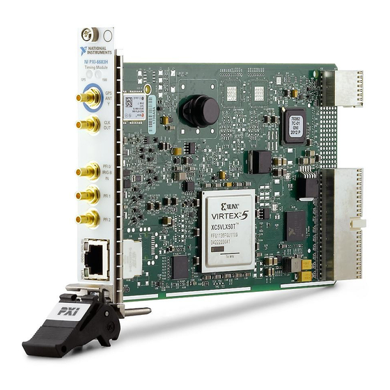
Hardware Overview This chapter presents an overview of the hardware functions of the NI PXI-6683 Series, shown in Figure 3-1. Figure 3-1. Isometric View of the NI PXI-6683 Series NI PXI-6683 NI PXI-6683H © National Instruments | 3-1... - Page 15 Chapter 3 Hardware Overview Figure 3-2 provides a functional overview of the NI PXI-6683 Series. Figure 3-2. Functional Overview of the NI PXI-6683 Not in NI PXI-6683H AC Coupled PXI_CLK10_IN CLKIN Clock Detector TCXO (Oscillator) CLKOUT AC Coupling PXI_CLK10 GPS RF IN...
-
Page 16: Ni Pxi-6683 Series Front Panel
NI PXI-6683 Series User Manual NI PXI-6683 Series Front Panel Figure 3-3 shows the connectors and LEDs on the front panel of the NI PXI-6683 Series. Figure 3-3. NI PXI-6683 Front Panel GPS LED PFI0/IRIG-B Input Connector 1588 LED PFI<1..2> Connectors... -
Page 17: Gps Led
Chapter 3 Hardware Overview GPS LED The GPS LED indicates the status of the GPS hardware. Refer to Figure 3-3 for the GPS LED location. Table 3-1 summarizes what the GPS LED indicates. Table 3-1. GPS LED Color Description Color Status Not using GPS* Amber... -
Page 18: Ethernet Speed Led
Blink Ethernet activity occurring Connectors This section describes the connectors on the front panel of the NI PXI-6683 Series. Refer to Figure 3-3 for the location of the connectors. • GPS ANT—GPS antenna RF input and DC power output for active GPS antenna. This connector provides 5 VDC for an active antenna. -
Page 19: Hardware Features
Connections that exceed any of the maximum ratings of input or output Caution signals on the NI PXI-6683 Series can damage the module, the computer, or other devices connected to the NI PXI-6683 Series. NI is not liable for any damage resulting from such signal connections. - Page 20 This signal is the PXI 10 MHz backplane clock. By default, this signal is the output of the native 10 MHz oscillator in the chassis. An NI PXI-6683 Series in the system timing slot can replace this signal with PXI_CLK10_IN. Oscillator This is the output of the 10 MHz TCXO.
-
Page 21: Clock And Event Generation
Clock and Event Generation The NI PXI-6683 Series can generate two types of clock signals. The first type is generated with a precise 10 MHz oscillator, and the second is generated with the synchronized timebase. The following sections describe the two types of clock generation and explain the considerations for choosing either type. -
Page 22: Time-Synchronized Clock And Event Generation
Routing Signals The NI PXI-6683 Series has versatile trigger routing capabilities. It can route signals to and from the front panel, the PXI star triggers, and the PXI triggers. In addition, the polarity of the destination signal can be inverted, which is useful when handling active-low digital signals. -
Page 23: Determining Sources And Destinations
Chapter 3 Hardware Overview Figure 3-4 summarizes the routing features of the NI PXI-6683 Series. The remainder of this chapter details the capabilities and constraints of the routing architecture. Figure 3-4. High-Level Schematic of NI PXI-6683 Signal Routing Architecture Not in NI PXI-6683H... -
Page 24: I/O Considerations
(auto-negotiation can be disabled by software). The Ethernet port is auto-MDI capable, which means crossover cabling is not necessary when connecting the NI PXI-6683 Series to another network card. The NI PXI-6683 Series senses whether a crossed connection is needed and performs the action internally. -
Page 25: Using Front Panel Pfi Terminals As Inputs
Do not attempt to drive signals into PFI terminals set up as outputs. Doing Caution so can damage the NI PXI-6683 Series or the device driving the PFI terminal. The signal source for each PFI trigger line configured as an output can be independently selected from one of the following options: •... -
Page 26: Note Regarding Pfi0
NI PXI-6683 Series User Manual Note Regarding PFI0 Since PFI0 is a dual-purpose terminal capable of performing digital I/O like the other PFI lines while also being capable of receiving IRIG-B AM and DC inputs, care is taken to protect the digital circuitry when PFI0 is being used as an IRIG-B AM input. -
Page 27: Using The Pxi Triggers
Controller Module installed in the system timing slot (such as the NI PXI-6683). The following sections describe in more detail the use of PXI triggers and PXI star triggers with the NI PXI-6683 series. Using the PXI Triggers The PXI trigger bus is a set of 8 electrical lines that go to every slot in a segment of a PXI chassis (multi-drop up to 8 slots). -
Page 28: Using The Pxi Star Triggers (Ni Pxi-6683 Only)
National Instruments does not recommend the use of PXI_Trigger lines for clock distribution. The preferred method for clock distribution is the use of the PXI_STAR triggers. However, the NI PXI-6683 Series does support routing of clocks to the PXI_Trigger lines, in case you must use them. -
Page 29: Choosing The Type Of Routing
Choosing the Type of Routing The NI PXI-6683 Series routes signals in one of two ways: asynchronously or synchronously. The following sections describe the two routing types and the considerations for choosing each type. -
Page 30: Synchronous Routing
Propagation delay of the signal through the NI PXI-6683 Series • Time for the receiver to recognize the signal The source of an asynchronous routing operation on the NI PXI-6683 Series can be any of the following lines: • Any front panel PFI pin (PFI<0..2>) •... - Page 31 Chapter 3 Hardware Overview Figure 3-7. Synchronous Routing Operation Setup Hold Time Time setup hold Trigger Input Synchronization Clock Clock to Output Time, t CtoQ Trigger Output Synchronous routing can be useful for eliminating skew when sending triggers to several destinations.
- Page 32 Any PXI Trigger line (PXI_TRIG<0..7>) In the NI PXI-6683 Series, the synchronization clock for synchronous routes is always PXI_CLK10. The destination of a synchronous routing operation on the NI PXI-6683 Series can be any of the following lines: • Any front panel PFI pin (PFI<0..2>) •...
-
Page 33: Gps
GPS enables the NI PXI-6683 Series to synchronize PXI systems located far away from each other, as long as GPS satellites are visible to the antenna from each location. Furthermore, once the NI PXI-6683 Series is synchronized to GPS, it can function as an IEEE 1588 grandmaster to enable synchronization of external 1588 devices. -
Page 34: Ieee 1588
Series to synchronize to IEEE 1588, in which case, the standard defines how the master will be selected. If the NI PXI-6683 Series is selected as IEEE 1588 master, and it is not configured to synchronize to GPS or IRIG-B, it will use its internal free-running timebase, which will be updated to the host computer’s system time during power up. -
Page 35: Pps
Perform the same steps listed above for any other synchronization partners/systems. Timing System Performance The NI PXI-6683 Series can generate or receive a 1 Hz pulse per second signal on any PFI or PXI Trigger terminal. You can set up this signal to transition on the seconds boundary of the synchronized system time. -
Page 36: Ieee 1588 Synchronization Best Practices
Windows configuration panels. GPS Synchronization Best Practices The NI PXI-6683 Series device has one SMB female connector on its front panel for a GPS active antenna. The connector provides a DC voltage to power the antenna and also serves as input for the GPS RF signal. -
Page 37: Maximum Cable Length
National Instruments recommends a GPS signal strength of between -135 dBm and -120 dBm at the NI PXI-6683 Series device SMB input. GPS signal strength on the Earth’s surface is typically -130 dBm. Targeting a signal strength of -125 dBm at the SMB input, you... -
Page 38: Calibration
The calibration constant is used at start-up when the board is configured for free running mode. When the NI PXI-6683 Series board is configured to use GPS, IEEE 1588, IRIG-B, or PPS as its time reference, the TCXO frequency is adjusted according to the time reference and the calibration constant is no longer used. -
Page 39: Appendix A Specifications
Stresses beyond those listed can cause permanent damage to the device. Exposure to absolute maximum rated conditions for extended periods of time can affect device reliability. Functional operation of the device outside the conditions indicated in the operational parts of the specification is not implied. © National Instruments | A-1... - Page 40 Appendix A Specifications PFI<0..2> Output Characteristics Frequency range..........DC to 50 MHz Output impedance ..........50 Ω, nominal Output coupling ..........DC Output voltage levels Output high ..........1.2 V min, 1.6 V typical for 50 Ω load to ground 2.6 V min, 3.3 V typical for 1 MΩ load Output low ..........0.1 V max, 0 V typical for 50 Ω...
- Page 41 NI PXI-6683 Series User Manual Input thresholds Voltage threshold high ......+2.3 V max Voltage threshold low ....... +0.8 V min Asynchronous delay, t PFI<0..2> to PXI_TRIG<0..7> output......17 to 20 ns, typical PFI<0..2> to PXI_STAR<0..12> output ....... 12 ns, typical...
- Page 42 2009. If the year is not supplied (sent as 00), the OS system time is read and the year is derived from it. To achieve proper synchronization of the NI PXI-6683 Series ensure that the IRIG-B source used conforms to the requirements listed above. Note that most IRIG-B sources conform to these requirements.
- Page 43 NI PXI-6683 Series User Manual Timestamping and Time-Synchronized Clock Generation Time-sychronized clock period and duty cycle resolution ..... 10 ns Clock signals generated on PFI, PXI_STAR (NI PXI-6683 only), or Note PXI Trigger lines must have a period and duty cycle that is a multiple of 10 ns.
- Page 44 Appendix A Specifications GPS Characteristics DC voltage output for antenna......+5 V, ±5% Maximum output current ........60 mA Minimum current for antenna Presence detection..........4.7 mA typical, 7.9 mA max Input impedance..........50 Ω, nominal GPS receiver type ..........50 channels, GPS L1 frequency (1575.42 MHz), C/A Code Recommended signal strength at SMB connector ..........-130 dBm...
- Page 45 NI PXI-6683 Series User Manual Physical Chassis requirement NI PXI-6683 ..........One 3U CompactPCI or PXI slot (PXI system timing slot for full functionality) NI PXI-6683H .......... One 3U CompactPCI, PXI, or PXI Express hybrid slot Weight NI PXI-6683 ..........186 g NI PXI-6683H ..........
- Page 46 All synchronization performance figures are based on empirical results and represent typical behavior. All figures are obtained recording the offset between PPS signals generated by two NI PXI-6683 Series boards, inside a closed PXI chassis, configured to synchronize to the particular time reference, at ambient room temperature. Synchronization was performed for 15 minutes before PPS offset recording began.
- Page 47 NI PXI-6683 Series User Manual Environmental Operating Environment Ambient temperature range ......0 to 55 °C (Tested in accordance with IEC 60068-2-1 and IEC 60068-2-2.) Relative humidity range........10% to 90%, noncondensing (Tested in accordance with IEC 60068-2-56.) Maximum altitude..........2,000 m (at 25 °C ambient temperature) Pollution Degree ..........
- Page 48 Appendix A Specifications Electromagnetic Compatibility This product is designed to meet the requirements of the following standards of EMC for electrical equipment for measurement, control, and laboratory use: • EN 61326 (IEC 61326): Class A emissions; Basic immunity • EN 55011 (CISPR 11): Group 1, Class A emissions •...
- Page 49 At the end of the product life cycle, all products must be sent to EU Customers a WEEE recycling center. For more information about WEEE recycling centers, National Instruments WEEE initiatives, and compliance with WEEE Directive 2002/96/EC on Waste and Electronic Equipment, visit ni.com/environment/...
- Page 50 This is usually specified by 3 digits that follow the IRIG standard name (for instance, IRIG-B 120). Table B-2 details the different characteristics of each IRIG option. © National Instruments | B-1...
- Page 51 Appendix B IRIG Protocol Overview Table B-2. IRIG Option Characteristics Carrier Signal Modulation type Frequency Information sent Pulse width TOY (BCD), CB, SBS modulated Amplitude 100 Hz TOY (BCD), CB modulated (sine wave) Manchester 1 kHz TOY (BCD) modulated 10 kHz TOY (BCD), SBS 100 kHz TOY (BCD), Year (BCD),...
- Page 52 NI PXI-6683 Series User Manual For amplitude modulated systems, the source must generate sinusoidal signaling modulating the amplitude such that it has a 10:3 mark:space amplitude ratio (the range of allowable mark to space ratios is 3:1 to 6:1). The source must phase align the generated sine wave such that the leading edges of bits are coincident with zero crossings of the sine wave.
- Page 53 Appendix B IRIG Protocol Overview Table B-3. IRIG-B Bit Assignments (Continued) Bit position Information transmitted Position identifier P 20 to 23 Units of hours 25 to 26 Tens of hours Position identifier P 30 to 33 Units of days 35 to 38 Tens of days Position identifier P 40 to 41...
- Page 54 NI PXI-6683 Series User Manual The NI PXI-6683 Series uses the time of day information transmitted as BCD to synchronize its internal timebase. If the IRIG-B signal includes the year, then it also uses that information to synchronize its clock. Otherwise, it gets the year from the host computer. The NI PXI-6683 Series disregards the rest of the information contained in the IRIG-B signal.
- Page 55 • System Integration—If you have time constraints, limited in-house technical resources, or other project challenges, National Instruments Alliance Partner members can help. To learn more, call your local NI office or visit ni.com/alliance © National Instruments | C-1...
- Page 56 Appendix C NI Services • Training and Certification—The NI training and certification program is the most effective way to increase application development proficiency and productivity. Visit for more information. ni.com/training – The Skills Guide assists you in identifying the proficiency requirements of your current application and gives you options for obtaining those skills consistent with your time and budget constraints and personal learning preferences.
- Page 57 ° degree Ω alternating current application development environment asynchronous a property of an event that occurs at an arbitrary time, without synchronization to a reference clock © National Instruments | G-1...
- Page 58 Glossary backplane an assembly, typically a printed circuit board (PCB), with 96-pin connectors and signal paths that bus the connector pins. PXI systems have two connectors, called the J1 and J2 connectors. the group of conductors that interconnect individual circuitry in a computer.
- Page 59 NI PXI-6683 Series User Manual data acquisition—(1) collecting and measuring electrical signals from sensors, transducers, and test probes or fixtures and inputting them to a computer for processing; (2) collecting and measuring the same kinds of electrical signals with A/D and/or DIO devices plugged into...
- Page 60 Measurement & a controlled centralized configuration environment that allows you to Automation Explorer configure all of your National Instruments DAQ, GPIB, IMAQ, IVI, (MAX) Motion, VISA, and VXI devices oscillator a device that generates a fixed frequency signal. An oscillator most often generates signals by using oscillating crystals, but also may use tuned networks, lasers, or atomic clock sources.
- Page 61 NI PXI-6683 Series User Manual Peripheral Component Interconnect—a high-performance expansion bus architecture originally developed by Intel to replace ISA and EISA. It is achieving widespread acceptance as a standard for PCs and work-stations; it offers a theoretical maximum transfer rate of 132 Mbytes/s.
- Page 62 Glossary seconds skew the actual time difference between two events that would ideally occur simultaneously. Inter-channel skew is an example of the time differences introduced by different characteristics of multiple channels. Skew can occur between channels on one module, or between channels on separate modules (intermodule skew).
- Page 63 Ethernet ACT/LINK LED, 3-5 (table), 3-5 Ethernet Speed LED, 3-5 Link LED color explanation (table), 3-5 GPS LED, 3-4 configuring the device PFI, 3-6 Ethernet Speed LED, 3-5 front panel PFI terminals, using as overview, 2-2 inputs, 3-12 © National Instruments | I-1...
- Page 64 (table), 3-4 light-emitting diode. See LED overview, 3-4 GPS synchronization, 4-1 best practices, 4-4 maximum signal rating (caution), 3-6 GPS, specifications, A-5 National Instruments support and hardware services, C-1 1588 LED overview, 3-4 network topology, 4-4 calibration, 5-1 NI PXI-6683 Series...
- Page 65 NI PXI-6683 Series User Manual using front panel PFI terminals as outputs, 3-12 safety, specifications, A-8 PFI synchronization clock, 3-6 shock and vibration specifications, A-8 physical specifications, A-6 signal source, 3-10 power requirement specifications, A-6 possible sources (table), 3-11 PPS synchronization, 4-2...
- Page 66 Index IRIG-B, 4-1 PFI synchronization clock, 3-17 PPS, 4-2 synchronization clock See also PXI_Trig/PXI_Star synchronization clock overview, 3-17 synchronization considerations operating environment, 4-3 timing system performance, 4-3 synchronized future-time clock generation specifications, A-4 synchronous routing overview, 3-17 timing diagram, 3-18 TCXO clock generation, 3-8 overview, 3-8...
Need help?
Do you have a question about the PXI-6683 Series and is the answer not in the manual?
Questions and answers