
Related Manuals for National Instruments NI PXI-6682H


Summary of Contents for National Instruments NI PXI-6682H
- Page 1 (217) 352-9330 | Click HERE Find the National Instruments PXI-6682 at our website:...
- Page 2 NI PXI-6682 User Manual Timing and Synchronization Module for PXI NI PXI-6682 User Manual October 2007 372292A-01 Artisan Technology Group - Quality Instrumentation ... Guaranteed | (888) 88-SOURCE | www.artisantg.com...
- Page 3 Thailand 662 278 6777, Turkey 90 212 279 3031, United Kingdom 44 (0) 1635 523545 For further support information, refer to the Technical Support and Professional Services appendix. To comment on National Instruments documentation, refer to the National Instruments Web site at and enter ni.com/info the info code feedback ©...
- Page 4 Instruments Corporation. National Instruments respects the intellectual property of others, and we ask our users to do the same. NI software is protected by copyright and other intellectual property laws. Where NI software may be used to reproduce software or other materials belonging to others, you may use NI software only to reproduce materials that you may reproduce in accordance with the terms of any applicable license or other legal restriction.
- Page 5 These classes are known as Class A (for use in industrial-commercial locations only) or Class B (for use in residential or commercial locations). All National Instruments (NI) products are FCC Class A products. Depending on where it is operated, this Class A product could be subject to restrictions in the FCC rules. (In Canada, the Department of Communications (DOC), of Industry Canada, regulates wireless interference in much the same way.) Digital...
-
Page 6: Table Of Contents
Contents About This Manual Conventions ........................vii National Instruments Documentation ................viii Related Documentation....................viii Chapter 1 Introduction What You Need to Get Started ..................1-1 Unpacking ........................1-2 Software Programming Choices ..................1-2 Safety Information ......................1-3 Chapter 2 Installing and Configuring Installing the Software ....................2-1 Installing the Hardware....................2-1... - Page 7 Contents Using the PXI Triggers ................... 3-13 Using the PXI Star Triggers................3-14 Choosing the Type of Routing ................ 3-15 Asynchronous Routing ..............3-15 Synchronous Routing ............... 3-16 Chapter 4 Synchronization GPS..........................4-1 IRIG-B........................... 4-1 IEEE 1588 ........................4-3 PPS ..........................4-3 Synchronization Best Practices ..................
-
Page 8: About This Manual
This font is also used for the proper names of disk drives, paths, directories, programs, subprograms, subroutines, device names, functions, operations, variables, filenames, and extensions. © National Instruments Corporation NI PXI-6682 User Manual Artisan Technology Group - Quality Instrumentation ... Guaranteed | (888) 88-SOURCE | www.artisantg.com... -
Page 9: National Instruments Documentation
About This Manual National Instruments Documentation NI PXI-6682 User Manual is one piece of the documentation set for your measurement system. You could have any of several other documents describing your hardware and software. Use the documentation you have as follows: •... -
Page 10: Introduction
NI-Sync User Manual, which you can find on the NI-Sync CD or download from ni.com/manuals © National Instruments Corporation NI PXI-6682 User Manual Artisan Technology Group - Quality Instrumentation ... Guaranteed | (888) 88-SOURCE | www.artisantg.com... -
Page 11: Unpacking
The LabVIEW Data Acquisition VI Library, a series of virtual instruments for using LabVIEW with National Instruments DAQ hardware, is included with LabVIEW. LabWindows/CVI is a complete ANSI C ADE that features an interactive user interface, code generation tools, and the LabWindows/CVI Data Acquisition and Easy I/O libraries. -
Page 12: Safety Information
Misuse of the product can result in a hazard. You can compromise the safety protection built into the product if the product is damaged in any way. If the product is damaged, return it to National Instruments for repair. Do not substitute parts or modify the product except as described in this document. - Page 13 Chapter 1 Introduction Operate the product at or below the installation category marked on the hardware label. Measurement circuits are subjected to working voltages and transient stresses (overvoltage) from the circuit to which they are connected during measurement or test. Installation categories establish standard impulse withstand voltage levels that commonly occur in electrical distribution systems.
-
Page 14: Installing And Configuring
Plug in and power on the chassis. The NI PXI-6682 is now installed. © National Instruments Corporation NI PXI-6682 User Manual Artisan Technology Group - Quality Instrumentation ... Guaranteed | (888) 88-SOURCE | www.artisantg.com... -
Page 15: Configuring The Module
Chapter 2 Installing and Configuring Configuring the Module The NI PXI-6682 is completely software configurable. The system software automatically allocates all module resources. The two LEDs on the front panel provide information about module status. The front panel description sections of Chapter 3, Hardware Overview, describe the LEDs in greater detail. -
Page 16: Hardware Overview
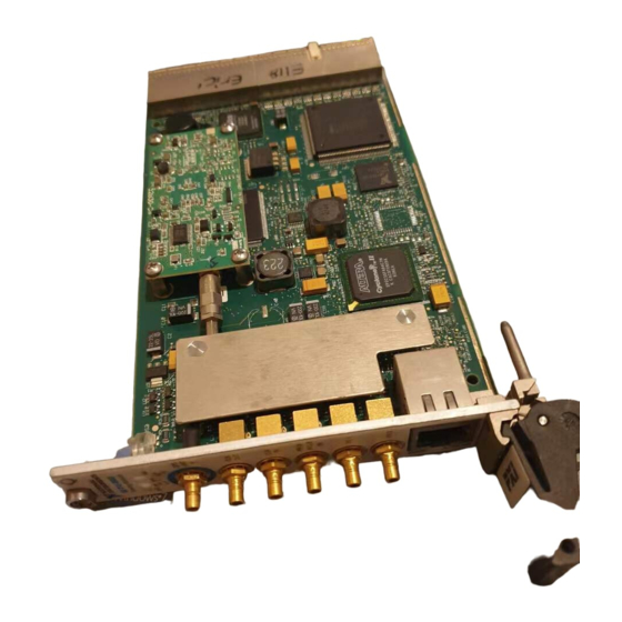
This chapter presents an overview of the hardware functions of the NI PXI-6682, shown in Figure 3-1. Figure 3-1. Isometric View of the NI PXI-6682 © National Instruments Corporation NI PXI-6682 User Manual Artisan Technology Group - Quality Instrumentation ... Guaranteed | (888) 88-SOURCE | www.artisantg.com... - Page 17 Chapter 3 Hardware Overview Figure 3-2 provides a functional overview of the NI PXI-6682. AC Coupled PXI_CLK10_IN CLKIN Clock Detector TCXO AC Coupling CLKOUT PXI_CLK10 To GPS GPS RF Antenna Detector PFI 0 IRIG-B Receiver PXI_STAR<0..12> Synchronization PFI0 Digital PXI_TRIG<0..7> Clock Generation Routing PFI 1...
-
Page 18: Ni Pxi-6682 Front Panel
The GPS LED indicates the status of the GPS hardware. Refer to Figure 3-3 for the GPS LED location. Table 3-1 summarizes what the GPS LED colors represent. © National Instruments Corporation NI PXI-6682 User Manual Artisan Technology Group - Quality Instrumentation ... Guaranteed | (888) 88-SOURCE | www.artisantg.com... -
Page 19: 1588 Led
Chapter 3 Hardware Overview Table 3-1. GPS LED Color Description Color Status Not using GPS* Amber Attempting to start self survey Blinking Amber Self survey in progress Blinking Green Self survey complete (normal operation) Error** * The GPS LED is turned off if GPS is not set as the time reference. ** An error is generated when the antenna is disconnected, when there is an antenna malfunction, or when there is a hardware malfunction. -
Page 20: Act/Link Led
PXI backplane (PXI_CLK10_IN) for distribution to the other modules in the chassis. © National Instruments Corporation NI PXI-6682 User Manual Artisan Technology Group - Quality Instrumentation ... Guaranteed | (888) 88-SOURCE | www.artisantg.com... -
Page 21: Hardware Features
Chapter 3 Hardware Overview • PFI <0..2>—Programmable Function Interface <0..2>. These connectors can be used for either input or output. You can program the behavior of these PFI connections individually. Additionally, PFI0 can function as an input for IRIG-B DC or AM. Caution Do not connect an AM signal to PFI0 when the PFI line is configured for digital operations. - Page 22 PXI chassis. The NI PXI-6682 can route a wide variety of signals to and from these lines. © National Instruments Corporation NI PXI-6682 User Manual Artisan Technology Group - Quality Instrumentation ... Guaranteed | (888) 88-SOURCE | www.artisantg.com...
-
Page 23: Clock And Event Generation
Chapter 3 Hardware Overview The remainder of this chapter describes how these signals are used, acquired, and generated by the NI PXI-6682 hardware, and explains how you can use the signals between various locations to synchronize events in your system. Clock and Event Generation The NI PXI-6682 can generate two types of clock signals. -
Page 24: Routing Signals
Figure 3-4 summarizes the routing features of the NI PXI-6682. The remainder of this chapter details the capabilities and constraints of the routing architecture. © National Instruments Corporation NI PXI-6682 User Manual Artisan Technology Group - Quality Instrumentation ... Guaranteed | (888) 88-SOURCE | www.artisantg.com... -
Page 25: Determining Sources And Destinations
Chapter 3 Hardware Overview ClkIn PXI_Clk10_In TCXO PXI_Clk10 ClkOut Router for each I/O PFI 0 PFI 2 PXI_Trig 0 PXI_Trig 0 Clk10 PXI_Trig 7 Synchronizer PXI_Trig 7 PXI_Star 0 PXI_Star 0 PXI_Star 12 PXI_Clk10 PXI_Star 12 PFI 0 PFI 2 Figure 3-4. -
Page 26: I/O Considerations
The Ethernet port also allows for full duplex operation, so traffic can be sent and received at the same time. © National Instruments Corporation 3-11 NI PXI-6682 User Manual Artisan Technology Group - Quality Instrumentation ... Guaranteed | (888) 88-SOURCE | www.artisantg.com... -
Page 27: Using Front Panel Pfi Terminals As Outputs
Chapter 3 Hardware Overview Using Front Panel PFI Terminals as Outputs The front panel PFI output signals use +3.3 V signaling for high-impedance loads. You can use the PFI terminals to generate future time events and clock signals up to 1.5 MHz. PFI output signals are suitable for driving most LEDs. -
Page 28: Note Regarding Pfi0
NI recommends transmitting clocks using the PXI_STAR triggers. However, if you must use the PXI Triggers, the frequency on the PXI Triggers should not exceed 20 MHz to preserve signal integrity. © National Instruments Corporation 3-13 NI PXI-6682 User Manual... -
Page 29: Using The Pxi Star Triggers
Chapter 3 Hardware Overview PXI Trigger signals do not reach each slot at precisely the same time. A difference of several nanoseconds between slots can occur in an eight-slot chassis. However, this delay is not a problem for many applications. If your application requires tighter synchronization, use the PXI_STAR triggers. -
Page 30: Choosing The Type Of Routing
Propagation delay of the signal across the backplane(s) and cable(s) • Propagation delay of the signal through the NI PXI-6682 © National Instruments Corporation 3-15 NI PXI-6682 User Manual Artisan Technology Group - Quality Instrumentation ... Guaranteed | (888) 88-SOURCE | www.artisantg.com... -
Page 31: Synchronous Routing
Chapter 3 Hardware Overview • Time for the receiver to recognize the signal The source of an asynchronous routing operation on the NI PXI-6682 can be any of the following lines: • Any front panel PFI pin (PFI<0..2>) • Any PXI Star trigger line (PXI_STAR<0..12>) •... - Page 32 The possible destinations for a synchronous route are identical to those for an asynchronous route. The destinations include any front panel PFI pin, any PXI star trigger line, or any PXI Trigger line. © National Instruments Corporation 3-17 NI PXI-6682 User Manual...
-
Page 33: Synchronization
IRIG standard, in which 100 bits of data are sent every second. Embedded in the data is a seconds’ boundary marker that the receiving © National Instruments Corporation NI PXI-6682 User Manual Artisan Technology Group - Quality Instrumentation ... Guaranteed | (888) 88-SOURCE | www.artisantg.com... - Page 34 Chapter 4 Synchronization instrument uses to synchronize its timebase to the IRIG source. The rest of the data contains information such as the time of day, days since the beginning of the year, and optionally, control functions and the number of seconds since the start of the day, encoded as a straight binary number.
-
Page 35: Ieee 1588
NI PXI-6682. While the NI PXI-6682 will function properly if you follow the specifications, the following guidelines may increase the synchronization performance. © National Instruments Corporation NI PXI-6682 User Manual Artisan Technology Group - Quality Instrumentation ... Guaranteed | (888) 88-SOURCE | www.artisantg.com... -
Page 36: Operating Environment
Chapter 4 Synchronization Operating Environment For best synchronization performance, follow these operating environment guidelines, while taking care to remain within the specified operating temperature limits: • Ensure the PXI filler panels are properly installed for unused PXI slots. Airflow can degrade the NI PXI-6682 performance because it tends to cause rapid changes in temperature. -
Page 37: Gps Synchronization Best Practices
30° angle with the ground. Locations far from trees and tall buildings which could reflect GPS satellite signals are best. © National Instruments Corporation NI PXI-6682 User Manual Artisan Technology Group - Quality Instrumentation ... Guaranteed | (888) 88-SOURCE | www.artisantg.com... -
Page 38: Appendix A Specifications
Functional operation of the device outside the conditions indicated in the operational parts of the specification is not implied. © National Instruments Corporation NI PXI-6682 User Manual Artisan Technology Group - Quality Instrumentation ... Guaranteed | (888) 88-SOURCE | www.artisantg.com... - Page 39 Appendix A Specifications CLKIN frequency accuracy requirement For replacing PXI_CLK10 ....±100 ppm Jitter added to CLKIN ......1.3 ps , 10 Hz to 100 kHz, typical Duty cycle distortion of CLKIN to PXI_CLK10_IN .........±1%, max Required input duty cycle.......45 to 55% PFI <0..2>...
- Page 40 Functional operation of the device outside the conditions indicated in the operational parts of the specifications is not implied. © National Instruments Corporation NI PXI-6682 User Manual Artisan Technology Group - Quality Instrumentation ... Guaranteed | (888) 88-SOURCE | www.artisantg.com...
- Page 41 Appendix A Specifications Decode Input voltage range ....1.5 V to 10 V peak-peak mark (3:1 ratio mark:space) Input carrier frequency ......1 kHz Do not connect an IRIG-B AM signal to PFI 0 when the input is configured for Caution digital operation, as this can result in damage of the digital input circuitry. IRIG-B DC compatibility .......IRIG-B 00X Input characteristics for IRIG-B DC..same as PFI digital input characteristics listed above...
- Page 42 DC voltage output for antenna ....5 V RF GPS signal frequency....... 1575.42 MHz ± 1.023 MHz Input impedance........50 Ω, nominal © National Instruments Corporation NI PXI-6682 User Manual Artisan Technology Group - Quality Instrumentation ... Guaranteed | (888) 88-SOURCE | www.artisantg.com...
- Page 43 Maximum signal loss at 1575.42 MHz...17 dB Note The GPS antenna kit offered by National Instruments comes with a 30 m cable which has a loss of 15 dB/100 ft, making the total loss in the cable approximately 14.8 dB.
- Page 44 PPS. The offset between their PPS signals was then measured over a 12 hour period. 7. IRIG-B performance depends on IRIG-B source stability and quality. © National Instruments Corporation NI PXI-6682 User Manual Artisan Technology Group - Quality Instrumentation ... Guaranteed | (888) 88-SOURCE | www.artisantg.com...
- Page 45 Appendix A Specifications Environmental Operating Environment Ambient temperature range ....0 to 55 °C (Tested in accordance with IEC-60068-2-1 and IEC-60068-2-2.) Relative humidity range......10% to 90%, noncondensing (Tested in accordance with IEC-60068-2-56.) Maximum altitude........2,000 m (at 25 °C ambient temperature) Pollution Degree ........2 Indoor use only.
-
Page 46: Safety
Certification column. Environmental Management National Instruments is committed to designing and manufacturing products in an environmentally responsible manner. NI recognizes that eliminating certain hazardous substances from our products is beneficial not only to the environment but also to NI customers. - Page 47 Waste Electrical and Electronic Equipment (WEEE) At the end of their life cycle, all products must be sent to a WEEE recycling EU Customers center. For more information about WEEE recycling centers and National Instruments WEEE initiatives, visit ni.com/environment/weee.htm RoHS...
-
Page 48: Irig Protocol Overview
© National Instruments Corporation NI PXI-6682 User Manual Artisan Technology Group - Quality Instrumentation ... Guaranteed | (888) 88-SOURCE | www.artisantg.com... - Page 49 Appendix B IRIG Protocol Overview transmitted. This is usually specified by 3 digits that follow the IRIG standard name (for instance, IRIG-B 120). Table B-2 details the different characteristics of each IRIG option. Table B-2. IRIG Option Characteristics Modulation type Frequency Information sent Pulse width modulated...
- Page 50 IRIG-B is one of the most common IRIG standards used. The following table describes how the information is transmitted when using IRIG-B each second. © National Instruments Corporation NI PXI-6682 User Manual Artisan Technology Group - Quality Instrumentation ... Guaranteed | (888) 88-SOURCE | www.artisantg.com...
- Page 51 Appendix B IRIG Protocol Overview Table B-3. IRIG-B Bit Assignments position Information transmitted Position identifier P (seconds’ boundary marker) 1–4 Units of seconds 6–8 Tens of seconds Position identifier P 10–13 Units of minutes 15–17 Tens of minutes Position identifier P 20–23 Units of hours 25–26...
- Page 52 To achieve proper synchronization of the NI PXI-6682 ensure that the IRIG-B source used conforms to the requirements listed above. Note that most IRIG-B sources conform to these requirements. © National Instruments Corporation NI PXI-6682 User Manual Artisan Technology Group - Quality Instrumentation ... Guaranteed | (888) 88-SOURCE | www.artisantg.com...
- Page 53 Technical Support and Professional Services Visit the following sections of the National Instruments Web site at for technical support and professional services: ni.com • Support—Online technical support resources at ni.com/support include the following: – Self-Help Resources—For answers and solutions, visit the...
- Page 54 Appendix C Technical Support and Professional Services • Calibration Certificate—If your product supports calibration, you can obtain the calibration certificate for your product at ni.com/calibration If you searched and could not find the answers you need, contact ni.com your local office or NI corporate headquarters. Phone numbers for our worldwide offices are listed at the front of this manual.
- Page 55 © National Instruments Corporation NI PXI-6682 User Manual Artisan Technology Group - Quality Instrumentation ... Guaranteed | (888) 88-SOURCE | www.artisantg.com...
- Page 56 Glossary backplane an assembly, typically a printed circuit board (PCB), with 96-pin connectors and signal paths that bus the connector pins. PXI systems have two connectors, called the J1 and J2 connectors. the group of conductors that interconnect individual circuitry in a computer. Typically, a bus is the expansion vehicle to which I/O or other devices are connected.
- Page 57 LabVIEW a graphical programming language light-emitting diode—a semiconductor light source © National Instruments Corporation NI PXI-6682 User Manual Artisan Technology Group - Quality Instrumentation ... Guaranteed | (888) 88-SOURCE | www.artisantg.com...
- Page 58 Measurement & a controlled centralized configuration environment that allows you to Automation Explorer configure all of your National Instruments DAQ, GPIB, IMAQ, IVI, (MAX) Motion, VISA, and VXI devices oscillator a device that generates a fixed frequency signal. An oscillator most often generates signals by using oscillating crystals, but also may use tuned networks, lasers, or atomic clock sources.
- Page 59 (for example, starting a data acquisition operation) © National Instruments Corporation NI PXI-6682 User Manual Artisan Technology Group - Quality Instrumentation ... Guaranteed | (888) 88-SOURCE | www.artisantg.com...
- Page 60 Glossary setup time setup volts virtual instrument NI PXI-6682 User Manual ni.com Artisan Technology Group - Quality Instrumentation ... Guaranteed | (888) 88-SOURCE | www.artisantg.com...
- Page 61 A-1 clock and event generation 1588 LED, 3-4 overview, 3-8 ACT/LINK LED, 3-5 clock generation connector descriptions, 3-5 © National Instruments Corporation NI PXI-6682 User Manual Artisan Technology Group - Quality Instrumentation ... Guaranteed | (888) 88-SOURCE | www.artisantg.com...
- Page 62 (caution), 3-6 connector descriptions, 3-5 GPS LED overview, 3-3 installing, 2-1 overview, 3-6 National Instruments support and services, Speed LED overview, 3-4 synchronization, 4-1 NI PXI-6682 User Manual ni.com Artisan Technology Group - Quality Instrumentation ... Guaranteed | (888) 88-SOURCE | www.artisantg.com...
- Page 63 2-1 signal description (table), 3-7 source PXI_CLK10_OUT possible sources (table), 3-11 signal description (table), 3-7 signal, 3-10 © National Instruments Corporation NI PXI-6682 User Manual Artisan Technology Group - Quality Instrumentation ... Guaranteed | (888) 88-SOURCE | www.artisantg.com...
- Page 64 Index specifications See also PXI_Trig/PXI_Star synchronization clock; PFI CE compliance, A-9 synchronization clock CLKIN characteristics, A-1 overview, 3-16 CLKOUT characteristics, A-1 synchronization considerations electromagnetic compatibility, A-9 operating environment, 4-4 environmental, A-8 timing system performance, 4-4 environmental management, A-9 synchronized future-time clock generation Waste Electrical and Electronic specifications, A-5 Equipment (WEEE), A-10...
Need help?
Do you have a question about the NI PXI-6682H and is the answer not in the manual?
Questions and answers