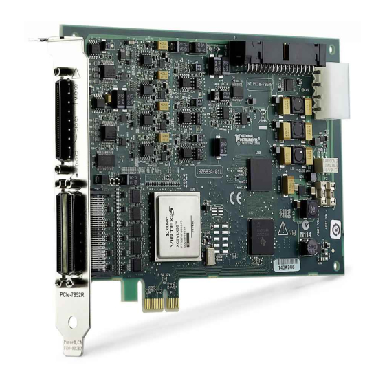
National Instruments R Series User Manual
R series reconfigurable i/o module (ai, ao, dio) for pxi express, 6 ai, 18 ao, 48 dio, 1 ms/s aio, 512 mb dram, kintex-7 325t fpga
Hide thumbs
Also See for R Series:
- User manual (72 pages) ,
- Getting started manual (12 pages) ,
- User manual (17 pages)
Table of Contents
Advertisement
Quick Links
USER MANUAL
NI PXIe-7868R
R Series Reconfigurable I/O Module (AI, AO, DIO) for PXI Express,
6 AI, 18 AO, 48 DIO, 1 MS/s AIO, 512 MB DRAM,
Kintex-7 325T FPGA
This document provides compliance, pinout, connectivity, mounting, and power information
for the NI PXIe-7868R.
Hardware Overview
The following high-level block diagram represents the NI PXIe-7868R.
Overvoltage
Protection
(x8)
Overvoltage
Protection
Overvoltage
Protection
Overvoltage
Protection
Overvoltage
Protection
Figure 1. NI PXIe-7868R Block Diagram
AI (x6)
ADC
INA
+5 V
Reference
AO (x18)
DAC
DIO (x16)
DIO (x32)
Device
Temperature
(x10)
100 MHz
DDR3 RAM
OSC
AI
AO
Kintex-7
Data/
FPGA
Address/
Control
DIO
Flash
Memory
NI ASIC
NI PXIe-7868R
Advertisement
Table of Contents

Summary of Contents for National Instruments R Series
- Page 1 USER MANUAL NI PXIe-7868R R Series Reconfigurable I/O Module (AI, AO, DIO) for PXI Express, 6 AI, 18 AO, 48 DIO, 1 MS/s AIO, 512 MB DRAM, Kintex-7 325T FPGA This document provides compliance, pinout, connectivity, mounting, and power information for the NI PXIe-7868R.
- Page 2 Pinout AI0+ 68 34 AI0– 68 34 68 34 AIGND0 67 33 AIGND1 EXTCLKIN 67 33 67 33 AI1+ 66 32 AI1– 66 32 66 32 AI2+ 65 31 AI2– DIO0 65 31 DIO1 65 31 AIGND2 64 30 AIGND3 64 30 64 30 AI3+...
-
Page 3: Connectivity Options
Connector Block RMIO Shielded Cable, 68 pin RMIO/RAO 189588-01 D-Type to 68 pin VHDCI (1 m) NI SHC68-68-RMIO RMIO Shielded Cable, 68 pin 189588-02 D-Type to 68 pin VHDCI (2 m) NI PXIe-7868R User Manual | © National Instruments | 3... -
Page 4: Analog Input
Analog Input The NI PXIe-7868R provides connections for six AI channels. Each channel has an AI+ pin, AI- pin, and AIGND pin to which you can connect both single-ended or differential voltage signals. Use the AISENSE pin to connect non-referenced single-ended signals. Connecting Single-Ended Voltage Signals To connect referenced single-ended voltage signals to the NI PXIe-7868R, you must connect the voltage ground signal to AI GND in order to keep the common-mode voltage in the... -
Page 5: Analog Output
NI PXIe-7868R Analog Output The NI PXIe-7868R provides connections for eighteen analog output channels. Each channel has an AO pin and AOGND pin to which you can connect a load. NI PXIe-7868R User Manual | © National Instruments | 5... - Page 6 Figure 6. Connecting a Load LOAD AOGND Connection NI PXIe-7868R Accessory Digital I/O The NI PXIe-7868R provides connections for 48 digital input/output (DIO) channels. Connector 0 contains 16 low-speed channels that can run up to 10 MHz signal frequencies and Connector 1 contains 32 high-speed DIO channels that can run up to 80 MHz signal frequencies.
-
Page 7: Field Wiring Considerations
+5 V Power Source Use the +5 V terminals on the I/O connector supply +5 V referenced to DGND to power external circuitry. NI PXIe-7868R User Manual | © National Instruments | 7... -
Page 8: Worldwide Support And Services
Never connect the +5 V power terminals to analog or digital ground or any other voltage source on the NI PXIe-7868R or any other device. Doing so can damage the device and the computer. National Instruments is not liable for damage resulting from such a connection.


Need help?
Do you have a question about the R Series and is the answer not in the manual?
Questions and answers