Omron HD-1500 Platform User Manual
Hide thumbs
Also See for HD-1500 Platform:
- User manual (256 pages) ,
- Assembly instructions manual (104 pages) ,
- Safety manual (70 pages)
Table of Contents
Advertisement
Quick Links
Advertisement
Table of Contents

Related Manuals for Omron HD-1500 Platform


Summary of Contents for Omron HD-1500 Platform
-
Page 1: I/O
HD-1500 Platform User’s Manual I645-E-01... - Page 2 Copyright Notice The information contained herein is the property of OMRON, and shall not be reproduced in whole or in part without prior written approval of OMRON. The information herein is subject to change without notice and should not be construed as a commitment by OMRON. The documentation is periodically reviewed and revised.
-
Page 3: Table Of Contents
Alert Levels Alert Icons Special Information 2.5 User's Responsibilities Electrical Hazards Magnetic Field Hazards Burn Hazard Qualification of Personnel Payload Movement and Transfer Configurable Warning Buzzer Fleet Management 2.6 Environment General Environmental Conditions 31500-000 Rev A HD-1500 Platform User's Manual... - Page 4 Installation 3.6 Attaching the Payload Structure and Options Attach the Payload Structure Attach the No Riding Warning Label Attach HD-1500 Optional Devices E-Stop Jumper on the User Access Panel Warning Buzzer Warning Light HD-1500 Platform User's Manual 31500-000 Rev A...
- Page 5 Payload Dimensions and Design Mounting Locations in the Platform AMR Coordinate System Center of Gravity (CG) 5.3 Payload-Related Tradeoffs 5.4 Connections Between the HD-1500 Platform and Payload Structure Operator Panel on the Payload Optional Connections Chapter 6: Connectivity 6.1 Required Connections...
- Page 6 Pendant Port Maintenance Ethernet Connection 7.5 Other Controls and Indicators Light Discs and Beacon Front and Back Light Strips 7.6 Sensors Lasers Other Sensors 7.7 Start up Procedure Pendant Controls and Operation Description HD-1500 Platform User's Manual 31500-000 Rev A...
- Page 7 Caster, Drive Wheel, and Drive Assembly 8.9 Restoring the Configuration Chapter 9: Options 9.1 Fleet Manager, for Multi-AMR Coordination 9.2 Pendant 9.3 Spare Battery 9.4 Side-Mount Lasers 9.5 High-Accuracy Positioning System (HAPS) 9.6 Charging Station 31500-000 Rev A HD-1500 Platform User's Manual...
- Page 8 Table of Contents Chapter 10: Technical Specifications 10.1 Dimension Drawings HD-1500 Platform HD-1500 Charging Station 10.2 HD-1500 Platform Specifications Physical Performance Sensors 10.3 HD-1500 Charging Station Specifications Power Supply Box Specifications Docking Target Specifications Chapter 11: HD-1500 Default Safety Zones 11.1 Default Safety Zones...
-
Page 9: Chapter 1: Introduction
Chapter 1: Introduction This manual is OMRON's Original instructions describing the setup, operation, and user main- tenance of an HD-1500 Autonomous Mobile Robot (AMR). This manual does not describe all configuration steps that you perform using the software sup- plied with an HD-1500. The Fleet Operations Workspace Core User's Manual (Cat. No. I635) describes configuration, and use of the HD-1500. -
Page 10: Product Description
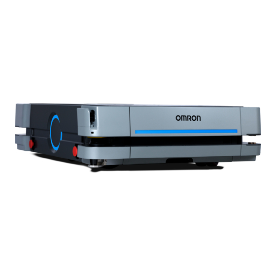
CAUTION: PROPERTY DAMAGE RISK The AMR skins can accumulate electrical charge which, if discharged into ESD sensitive devices, can cause damage to those devices. Figure 1-1. HD-1500 Platform Features HD-1500 Platform User's Manual 31500-000 Rev A... - Page 11 Light Disc x2 - one on each side Drive Wheel x2 - one on each side of of the HD-1500 the HD-1500 Speaker x2 AMR Controller Battery Battery Door Figure 1-2. Charging Station Features 31500-000 Rev A HD-1500 Platform User's Manual...
-
Page 12: Hd-1500 Autonomous Navigation
Payload Structures on page 136. The platform also provides a variety of interfaces and power connections to support your application-specific sensors and accessories. For more information on available user con- nectors, see: Connectivity on page 150. HD-1500 Platform User's Manual 31500-000 Rev A... -
Page 13: Body And Drive Train
AMR's longitudinal center-line. This arrangement allows the AMR to maintain contact with the floor over uneven areas or bumps, which benefits both traction and stability. Refer to the following figure for more inform- ation. 31500-000 Rev A HD-1500 Platform User's Manual... -
Page 14: What's Included - Basic Components
Figure 1-4. HD-1500 Drive Train (A) Casters, (B) Drive Wheels, (C) Rocker Arms, and (D) Drive Motor (one on each drive wheel) What's Included - Basic Components One fully-assembled HD-1500Platform which includes: Two OMRON OS32C Safety Scanning Lasers (main lasers). Two low lasers. Differential drive train. Skins. - Page 15 See: Pos- itioning an Optional Payload E-Stop on page 197. For information on the dimensions of the Operator Panel, see: Operator Panel on the Payload on page 147. 31500-000 Rev A HD-1500 Platform User's Manual...
- Page 16 AMRs. Figure 1-8. and Figure 1-9. display the location of the pendant, and the Ethernet ports on the Operator Panel, installed on the rear of the HD-1500. HD-1500 Platform User's Manual 31500-000 Rev A...
- Page 17 This is used for manually controlling the platform, mostly when making a scan to be used for generating a map. Callout Control Function Callout Control Function Speed control Power indicator LED Goal button Trigger switch Three-position enabling device Directional control stick 31500-000 Rev A HD-1500 Platform User's Manual...
- Page 18 Figure 1-8. (A) Pendant, (B) Pendant port on the Operator Panel, and (C) Operator Panel Location on the HD-1500 Pendant Figure 1-9. (A) PC, (B) Maintenance Ethernet Port on the Operator Panel, and (C) Operator Panel on the HD-1500 HD-1500 Platform User's Manual 31500-000 Rev A...
-
Page 19: Optional Features And Components (Partial List)
AMR fleet. See the following documents for detailed information: Enterprise Manager 2100 User's Guide (Cat. No. I631) Fleet Operations Workspace Core User's Manual (Cat. No. I635) 31500-000 Rev A HD-1500 Platform User's Manual... - Page 20 To configure and manage an HD-1500 you require a personal computer (PC) running a sup- ported version of Microsoft Windows®. The PC requires: 200 megabytes of available hard-disk storage. Ethernet connection. OMRON recommends that you use a stable and high-speed HD-1500 Platform User's Manual 31500-000 Rev A...
- Page 21 ARAMCentral runs on the Fleet Manager as part of the Fleet Operations Workspace software. When managing a fleet, the ARAMCentral software does the following: Stores and distributes: The shared workspace map used by all AMRs in a fleet. The common AMR configuration. Controls AMR traffic, including: 31500-000 Rev A HD-1500 Platform User's Manual...
- Page 22 In particular, refer to the descriptions of the following software options: Working With Map Files - Editing a Map File Using the Drawing Tools - Adding Goals and Docks HD-1500 Platform User's Manual 31500-000 Rev A...
-
Page 23: Setnetgo
To access the SetNetGo web interface, at a minimum, you need: A hardwired connection to the HD-1500 Maintenance Ethernet port, located on the Oper- ator panel. A LAN connection or direct Ethernet port connection to the EM2100 maintenance port. 31500-000 Rev A HD-1500 Platform User's Manual... -
Page 24: How Can I Get Help
Use ARCL to integrate a fleet of AMRs with an external automation system. Support Contact your OMRON representative if you have further inquiries with your HD-1500 that are not described in this manual. HD-1500 Platform User's Manual 31500-000 Rev A... -
Page 25: Download A Debuginfo File For Support
When you contact support, it is useful to provide a DebugInfo file. This is a collection of con- figuration, log, and system status files that support personnel can use for debugging and troubleshooting. Visit the OMRON Web site for your locale to obtain local support telephone numbers and information. Download a Debuginfo File for Support You can download a debuginfo file for troubleshooting problems or if you need to contact your OMRON representative. - Page 26 1.4 How Can I Get Help? 2. Click Download debug info. 3. When prompted, save the downloaded file, and attach it to your support request email. See: Support on page 25. HD-1500 Platform User's Manual 31500-000 Rev A...
-
Page 27: Chapter 2: Safety
You must make sure that the operating environment of the AMR is adequately controlled. Do not expose the AMR to rain or moisture. Do not use unauthorized parts to repair the AMR. 31500-000 Rev A HD-1500 Platform User's Manual... -
Page 28: Unprotected Areas
2.2 Unprotected Areas Do not power on the AMR without its wireless antennas in place. Although the lasers used are Class 1 (eye-safe), OMRON recommends that you not look into the laser light. Reflective surfaces can interfere with the AMR's laser operation. - Page 29 It is the end user's responsibility to ensure that the area within the radius of 2 m from the center of the HD-1500 is kept clear, when the AMR is traveling at less than 115 mm/s. 31500-000 Rev A HD-1500 Platform User's Manual...
- Page 30 The following figure provides dimensions of the HD-1500 unprotected area. The same dimen- sions are true for the rear laser unprotected area. Figure 2-3. HD-1500's Unprotected Zone Dimensions - Movement at Less Than 115 mm/s, (A) AMR Y-Axis, and (B) AMR X-Axis HD-1500 Platform User's Manual 31500-000 Rev A...
-
Page 31: What To Do In An Emergency
Figure 2-5. E-Stop Button on the Operator Panel Use the User Safety Interface connection, located on the user access panel, to add E-Stop but- tons to your payload structure, if required. See: SCPU on page 161. 31500-000 Rev A HD-1500 Platform User's Manual... -
Page 32: Releasing The Brakes
3% will cause the HD-1500 to roll down. You must not use the brake release button to move the HD-1500 manually, when positioned on a slope of greater than 3%, unless necessary precautions have been taken to pre- HD-1500 Platform User's Manual 31500-000 Rev A... -
Page 33: Releasing An E-Stop
This should be as low as possible and near the center of gravity. OMRON recommends that you train personnel on the safe use of the brake release button, and procedures for safely pushing an HD-1500. For instructions on how to safely use the brake release button, see: Brake Release Button on page 198. -
Page 34: Dangers, Warnings, And Cautions
ESD situation. ation. This warning icon warns This identifies a fire risk. against riding on the AMR. This warning icon warns This identifies a tip haz- against hazardous ard. magnetic field. HD-1500 Platform User's Manual 31500-000 Rev A... -
Page 35: Special Information
Special Information This manual uses the following typographic styles to identify specific types of information: IMPORTANT: Information to ensure safe use of the product. NOTE: Information for more effective use of the product. 31500-000 Rev A HD-1500 Platform User's Manual... - Page 36 2.4 Dangers, Warnings, and Cautions Additional Information: Offers helpful tips, recommendations, and best prac- tices. Version Information: Information on differences in specifications for different versions of hardware or software. HD-1500 Platform User's Manual 31500-000 Rev A...
-
Page 37: User's Responsibilities
Mechanically maintain and service AMRs for proper operation of all control and safety functions. Electrical Hazards WARNING: ELECTROCUTION RISK The charging station has AC power inside. Its covers are not interlocked. You must disconnect the power prior to maintenance work. 31500-000 Rev A HD-1500 Platform User's Manual... -
Page 38: Magnetic Field Hazards
Never access the interior of the platform with the charger attached. Avoid shorting the battery terminals or connectors. Do not use any charger or battery not supplied by OMRON. The charger shall only be used to charge an HD-1500 battery. -
Page 39: Burn Hazard
A typical AMR application uses a payload structure to transport objects within a facility. For example, the AMR might pick up and carry a crate of engine parts from one conveyor belt then deliver it to another conveyor belt. 31500-000 Rev A HD-1500 Platform User's Manual... -
Page 40: Configurable Warning Buzzer
WARNING: PERSONAL INJURY OR PROPERTY DAMAGE RISK It is the end user's responsibility to ensure that the payload is properly secured to the HD-1500 platform, and that the payload does not experience any shifting during movement of the AMR. For example, when transporting containers of liquids, the operator must take necessary precautions to prevent sloshing of the fluid as it affects the stability of the AMR. -
Page 41: Fleet Management
An AMR can be unsafe if operated under environmental conditions other than those specified in this manual. Environmental Hazards—These are areas where it is unsafe for the HD-1500 to operate. Provide physical barriers that the HD-1500 can detect accurately with its scanning laser 31500-000 Rev A HD-1500 Platform User's Manual... -
Page 42: Public Access
You must deploy it only in applications where you anticipate and mitigate potential risks to personnel and equipment. OMRON intends for the HD-1500 to be used in controlled areas for which a risk assessment has been conducted. OMRON does not intend the HD-1500 to be used in, for example, areas open to general public access. - Page 43 Figure 2-7. Goal Position - Measured From the Center of the Docking Target to the Center of the HD-1500, (A) Docking Target, and (B) HD-1500 31500-000 Rev A HD-1500 Platform User's Manual...
-
Page 44: Obstacles
The HD-1500 provides programmable warning features such as a warning buzzer, speech synthesis, and warning indicator lights. The user access panel provides user ports that enable you to add warning indicators to your payload structure. See: User Access Panel Connections on page 155 HD-1500 Platform User's Manual 31500-000 Rev A... -
Page 45: Intended And Non-Intended Use
CG. See: Center of Gravity (CG) on page 143. OMRON does not provide the method of loading the payload onto or off the HD-1500. It is the end user's responsibility to perform a complete task-based risk assessment in accordance with EN ISO 12100, and ensure safe transfer of the payload. -
Page 46: Non-Intended Use
IMPORTANT: The HD-1500 is not intended to operate in a damp/wet environment where it will be exposed to liquid or liquid ingress. In addition, OMRON does not intend the HD-1500 for deployment in the following envir- onments: Outdoor or uncontrolled areas without risk analysis. -
Page 47: Hd-1500 Platform Modifications
You perform proper risk assessment in accordance with EN ISO 12100, and identify any risks associated with the modification made to the HD-1500 platform. It is the end- user's responsibility to ensure that these risks are properly mitigated/eliminated, so the AMR does not cause personal injury or property damage. -
Page 48: Protective Stops Initiated By Amr Safety Lasers
This may cause the AMR to turn around, and move in a different direction. If no such path is available, the AMR fails the current job, and waits for the Fleet Manager to assign a new job. HD-1500 Platform User's Manual 31500-000 Rev A... -
Page 49: Safety System Overspeed Faults
Class 1 laser, which is an invisible laser radiation, is safe under all conditions of normal use. However, the maximum permissible exposure cannot be exceeded when viewing the laser with the naked eye. OMRON recommends that you avoid long-term viewing of the laser. 31500-000 Rev A... -
Page 50: Interlock Switches
Figure 2-10. Location of the Interlock Switch on the Electronics Bay Access Door Frame HD-1500 Platform User's Manual 31500-000 Rev A... -
Page 51: Battery Safety
NOTE: After receiving the battery, check its state of charge by pressing and hold- ing in the push-button on the battery indicator. If the battery is in a low charge state, you must immediately charge to a full charge to avoid discharging the 31500-000 Rev A HD-1500 Platform User's Manual... -
Page 52: Battery Safety Precautions
Store the batteries on a flat surface, and in an area free of vibration. Do not stack anything on top of the batteries. Never expose the battery to water. If the battery is leaking, use a chemical neutralizer HD-1500 Platform User's Manual 31500-000 Rev A... - Page 53 You should place the leaking battery in a bag or a drum containing the chemical neut- ralizer, and contact your OMRON representative. IMPORTANT: You must wear proper PPE when working around a leak- ing battery.
-
Page 54: Battery Maintenance
Due to high power transfer, OMRON has taken several safety measures to keep the users safe: The electrician access box has a main disconnect switch, as displayed in Figure 7-10. -
Page 55: Safety Precautions
AC supplied to the power supply box, the blue LED is off. 3. Next, disconnect the facility power to the facility power cable. This will disconnect the facility AC power to the electrician access box. 31500-000 Rev A HD-1500 Platform User's Manual... - Page 56 For instructions on how to safely move the power supply box refer to Power Supply Box Unpacking on page 95. The power supply box must be installed according to the local regulations or codes, and by authorized personnel or licensed electricians. HD-1500 Platform User's Manual 31500-000 Rev A...
-
Page 57: Additional Safety Information
NOTE: The IP rating for the copper charging pads is IP10. Do not expose them to liquid. 2.14 Additional Safety Information Contact your OMRON representative for other sources of safety information. Mobile Robot HD Safety Manual (Cat. No. I647) The Mobile Robot HD Safety Manual (Cat. No. I647) is included with your HD-1500 and provides detailed information about safe operation of your HD-1500. -
Page 59: Chapter 3: Setup
OMRON representative. Tasks The tasks required to set up an HD-1500 are: Install the charging station. -
Page 60: Battery Crate
Ship and store the HD-1500 battery only under the conditions described in this section. Storage Requirements OMRON recommends the following temperatures based on the duration of storage: -20 to 35°C, 5-95% RH non-condensing For transportation of up to 2 weeks, the manufacturer recommends: -20 to 60°C, 5-95% RH non-condensing... -
Page 61: Power Supply Box, And Docking Target Crates
The original shipping crates, which are designed to prevent damage from shock and vibration in transit. Protect the crates from excessive shock and vibration. Use a rated forklift, pallet jack or similar devices to move the shipping crates. 31500-000 Rev A HD-1500 Platform User's Manual... -
Page 62: Before Unpacking
If the items received do not match the packing slip, or are damaged, do not accept the delivery. If the items received do not match your order, contact your OMRON representative immediately. Retain the containers and packaging materials. These items may be necessary to settle claims or, at a later date, to relocate the equipment. - Page 63 The impact driver is used to remove side screws connecting the with impact housing crate to the base pallet. driver Screwdriver, or Screwdriver, or the hammer is used to remove the metal clips hammer attaching the front panel to the housing crate. 31500-000 Rev A HD-1500 Platform User's Manual...
-
Page 64: Hd-1500 Unpacking
Plywood base pallet Crate top section - stores the ramps First ramp Second ramp Wood rails The following figure illustrates the movement of the HD-1500 down the ramp, and on to the floor. HD-1500 Platform User's Manual 31500-000 Rev A... - Page 65 Chapter 3: Setup Figure 3-2. HD-1500 Moving Down the Ramp The following figures display dimensions of the HD-1500 crate. All dimensions are in mm. 1448 1969 Figure 3-3. HD-1500 Shipping Crate Outer Dimensions 31500-000 Rev A HD-1500 Platform User's Manual...
- Page 66 3.4 Unpacking Considerations 1918 1397 Figure 3-4. HD-1500 Shipping Crate Inner Dimensions HD-1500 Platform User's Manual 31500-000 Rev A...
- Page 67 6. Remove the metal clips attaching the front panel to the housing crate using a screw- driver, or a hammer. Place the screwdriver or the hammer in between the crate and the metal clips, and apply enough force to remove the clips. 31500-000 Rev A HD-1500 Platform User's Manual...
- Page 68 Figure 3-7. Removing the Front Panel 8. The HD-1500 crate contains two ramps (located on the top section of the crate, as dis- played in the following figure). The ramps will be used to transport the HD-1500 onto HD-1500 Platform User's Manual 31500-000 Rev A...
- Page 69 Use the ramp handles located on each side of the ramp to carry them. Figure 3-8. Ramps in the Crate, (A) First Ramp, and (B) Second Ramp Figure 3-9. Pulling the First Ramp Out of the Crate 31500-000 Rev A HD-1500 Platform User's Manual...
- Page 70 3.4 Unpacking Considerations Figure 3-10. Removing the Second Ramp from the Crate Figure 3-11. Using the Handles to Carry the Ramp HD-1500 Platform User's Manual 31500-000 Rev A...
- Page 71 Figure 3-13. Support Bars in Upright Position 10. Flip the ramp so the ramp sits on its support bars. 11. Then, put guard rails in upright position. The guard rails prevent the HD-1500 from tip- ping off the ramps. 31500-000 Rev A HD-1500 Platform User's Manual...
- Page 72 Figure 3-15. Placing the First Ramp Over the Edge of the Housing Crate 13. Position the second ramp so it is aligned with the first one. Connect and secure the two ramps using the locking clip. HD-1500 Platform User's Manual 31500-000 Rev A...
- Page 73 Figure 3-16. The Two Ramps Installed Figure 3-17. Ramps Connected and Secured by the Locking Clips 14. Remove the housing crate, using two persons, each pushing one side of the housing crate away from the base pallet. 31500-000 Rev A HD-1500 Platform User's Manual...
- Page 74 Unbuckle the strap's lever, and then pull the lever all the way to the end of the strap. Figure 3-19. Unbuckling the Straps Once the straps are loosened, you can remove the wood bars used to secure the HD- HD-1500 Platform User's Manual 31500-000 Rev A...
- Page 75 18. Once the battery is installed, you need to connect the pendant to the HD-1500 in order to drive the HD-1500 down the ramp. Connect the pendant to the pendant port located on the HD-1500 Operator Panel. 31500-000 Rev A HD-1500 Platform User's Manual...
- Page 76 19. Press the ON button on the operator panel, and use the pendant to drive the HD-1500 down the ramp and on to the floor. Figure 3-22. Driving the HD-1500 Down the Ramp Using the Pendant HD-1500 Platform User's Manual 31500-000 Rev A...
- Page 77 Chapter 3: Setup Figure 3-23. HD-1500 on the Floor 31500-000 Rev A HD-1500 Platform User's Manual...
-
Page 78: Battery Unpacking
IMPORTANT: The battery weighs 68 kg. There must be at least 3 persons lifting the battery. Description Image Crate top cover - to be used as a ramp Crate front panel Base pallet Latches Protective foams HD-1500 Platform User's Manual 31500-000 Rev A... - Page 79 Chapter 3: Setup The following figures display dimensions of the battery crate. All dimensions are in mm. 1118 Figure 3-24. Battery Crate Outer Dimensions 1041 Figure 3-25. Battery Crate Inner Dimensions 31500-000 Rev A HD-1500 Platform User's Manual...
- Page 80 Follow these steps to remove the battery from its shipping crate: 1. Unlock the top cover latches by twisting them, as displayed in the following figure. Figure 3-27. Twisting the Latch to Unlock the Top Cover HD-1500 Platform User's Manual 31500-000 Rev A...
- Page 81 Figure 3-28. Removing the Top Cover 3. Unlock the front panel latches (similar to how it was done for the top cover), and remove the front panel. 31500-000 Rev A HD-1500 Platform User's Manual...
- Page 82 3.4 Unpacking Considerations Figure 3-29. Unlatching the Front Panel Figure 3-30. Removing the Front Panel HD-1500 Platform User's Manual 31500-000 Rev A...
- Page 83 4. Place the rear edge of the top cover over crate's front edge as displayed in the following figure. This allows you to use the top cover as a ramp. Figure 3-31. Using the Top Cover as a Ramp 5. Next, remove the protective foams from the top cover. 31500-000 Rev A HD-1500 Platform User's Manual...
- Page 84 3.4 Unpacking Considerations Figure 3-32. Protective Foams Removed 6. The battery has a handle that can extend out. Unlatch the battery locks and extend the handle out. Figure 3-33. Unlatching the Battery Locks HD-1500 Platform User's Manual 31500-000 Rev A...
- Page 85 These wheels allow you to roll the battery on the floor and carry it similar to how would you carry a suitcase. Figure 3-35. Rolling the Battery Down the Ramp 31500-000 Rev A HD-1500 Platform User's Manual...
- Page 86 3.4 Unpacking Considerations Figure 3-36. Battery Case Roller Wheels After unpacking, you may install the battery in the platform. For information on how to install the battery, see: Installing the Battery on page 104. HD-1500 Platform User's Manual 31500-000 Rev A...
-
Page 87: Docking Target Unpacking
IMPORTANT: The docking target weighs 39 kg. There must be at least 2 per- sons lifting the docking target. Description Image Crate housing Crate front panel Base pallet Protective wood Wooden board Protective foam 31500-000 Rev A HD-1500 Platform User's Manual... - Page 88 3.4 Unpacking Considerations The following figures display dimensions of the docking target crate. All dimensions are in 1565 Figure 3-37. Docking Target Outer Dimensions 1514 Figure 3-38. Docking Target Inner Dimensions HD-1500 Platform User's Manual 31500-000 Rev A...
- Page 89 Figure 3-40. Front Panel Removed 3. Remove the screws attaching the housing crate to the base pallet using a 13 mm socket with impact driver. 4. Next, remove the housing crate by pulling it away. 31500-000 Rev A HD-1500 Platform User's Manual...
- Page 90 6. Once the strap is loosened, remove the protective wood along with the strap. HD-1500 Platform User's Manual 31500-000 Rev A...
- Page 91 7. Untighten the bolts attaching the wooden board to the base pallet. Then, unstrap the pro- tective foam, and remove the wooden board. The protective foam prevents damage to the charging paddle during vibration or shock. IMPORTANT: Take care not to damage/scratch the copper charging pads during unpacking. 31500-000 Rev A HD-1500 Platform User's Manual...
- Page 92 Figure 3-43. (A) Strap Holding the Protective Foam, (B) Protective Foam, and (C) Wooden Board Figure 3-44. Bolt Securing the Wooden Board to the Base Pallet 8. Then, using lifting recesses, located on each side of the docking target, lift and place the HD-1500 Platform User's Manual 31500-000 Rev A...
- Page 93 Figure 3-45. Lifting Recesses on the Right and Left Side of the Docking Target After unpacking, you may install the docking target to your designated location in the facility. For information on how to install the docking target, see: Installing the Charging Station on page 110. 31500-000 Rev A HD-1500 Platform User's Manual...
-
Page 94: Power Supply Box Unpacking
CAUTION: PERSONAL INJURY RISK Use safe lifting practices when moving the power supply box. IMPORTANT: The power supply box itself weighs 105 kg. There must be at least 3 persons lifting the power supply box. HD-1500 Platform User's Manual 31500-000 Rev A... - Page 95 Chapter 3: Setup Description Image Crate housing Crate front panel Plywood base pallet 31500-000 Rev A HD-1500 Platform User's Manual...
- Page 96 3.4 Unpacking Considerations The following figures display dimensions of the power supply box crate. All dimensions are in 1092 1454 Figure 3-46. Power Supply Box Outer Dimensions HD-1500 Platform User's Manual 31500-000 Rev A...
- Page 97 Chapter 3: Setup 1041 1302 Figure 3-47. Power Supply Box Inner Dimensions 31500-000 Rev A HD-1500 Platform User's Manual...
- Page 98 Follow these steps to remove the power supply box from its shipping crate: 1. Remove the clips holding the front panel to the housing crate using a screw driver or any tool that allows you to remove the clips. Figure 3-49. Removing the Clips HD-1500 Platform User's Manual 31500-000 Rev A...
- Page 99 3. Remove the screws attaching the base pallet to the housing crate, using a 13 mm socket with impact driver. Figure 3-51. Removing the Screws Attaching Base Pallet to the Housing Crate 4. Remove the plastic wrap covering the power supply box. 31500-000 Rev A HD-1500 Platform User's Manual...
- Page 100 3.4 Unpacking Considerations Figure 3-52. Remove the Plastic Cover 5. Pull and remove the housing crate as displayed in the following figure. HD-1500 Platform User's Manual 31500-000 Rev A...
- Page 101 Figure 3-53. Pulling the Housing Crate Away 6. Then, remove the six bolts attaching the power supply box to the base pallet, using a 14 mm socket wrench. Figure 3-54. (3) Bolts on Each Leg 31500-000 Rev A HD-1500 Platform User's Manual...
- Page 102 WARNING: PROPERTY DAMAGE RISK The slings must be evenly distributed to ensure that the power supply box is leveled when lifted up. Figure 3-56. Passing the Safety-Rated Slings Through the Eye Bolt HD-1500 Platform User's Manual 31500-000 Rev A...
-
Page 103: Installing The Battery
3.5 Installing the Battery Your HD-1500 ships fully-assembled, excluding its battery. Air shipping regulations require that the battery is packaged and shipped separately. IMPORTANT: You may only use the OMRON-supplied battery for the HD-1500 AMR. Installation Before you begin, press an E-Stop button and turn the HD-1500 off. - Page 104 3. Use the extended handle to push the battery into the platform. See: Figure 3-59. As the battery gets pushed in, the power connector installed on top of the battery case makes a blind-mate connection with the power connector attached to the chassis. HD-1500 Platform User's Manual 31500-000 Rev A...
- Page 105 Figure 3-59. Lifting the Battery and Pushing into the Platform 4. Collapse the handle before pushing the battery all the way into the platform. Figure 3-60. Collapsing the Battery Handle 5. Lock the two latches to secure the battery handle in place. 31500-000 Rev A HD-1500 Platform User's Manual...
- Page 106 7. Push the battery all the way in, and close the battery door. Take care not to tangle or crush the Ethernet cable when pushing the battery into the platform. The battery door holds the battery tightly in place, and keeps it from shifting inside the HD-1500 Platform User's Manual 31500-000 Rev A...
-
Page 107: Attaching The Payload Structure And Options
Attach the Payload Structure You will need to attach the payload structure you designed and built to the platform. Because the payload structure is user-designed, OMRON only provides the mounting hole pattern information. Refer to: Payload Dimensions and Design on page 139. -
Page 108: E-Stop Jumper On The User Access Panel
To conform to applicable standards, the buzzer must be audible in all oper- ating conditions and environments. Also, the buzzer shall be audible above the ambient noise of the environment that the HD-1500 operates in. It is the end-user's responsibility to verify this requirement. HD-1500 Platform User's Manual 31500-000 Rev A... -
Page 109: Warning Light
The power supply box air vents (top and bottom) must not be blocked. Blocking the air vents will trap the air inside the power supply box which could be hazardous since it 31500-000 Rev A HD-1500 Platform User's Manual... -
Page 110: Required Tools And Fasteners
M10 washer - used with the M10 bolts. (user-supplied) M8 bolts - used to mount the docking target to the floor/wall. (user-sup- plied) Docking target mounting brackets. (OMRON-supplied, part number 68910-105) Cable clampFigure 3-67. HD-1500 Platform User's Manual 31500-000 Rev A... -
Page 111: Charging Station Features And Parts
The power supply box, transfers power to the docking target using a power cord. Figure 3-64. AMR Mating with the Charging Paddle Docking Target - Features and Parts Figure 3-65. Docking Target - Features and Parts 31500-000 Rev A HD-1500 Platform User's Manual... - Page 112 Mounting brackets x8 Retractable cover (M8 bolts) Docking Target - Dimensions Figure 3-66. Docking Target Dimensions, (A) Wall Mount Brackets, and (B) Floor Mount Brackets (units are in mm) HD-1500 Platform User's Manual 31500-000 Rev A...
- Page 113 There are four LED indicators on the power supply box, as displayed in Figure 3-67. For information on the power supply box LED indicators, see: Indicators, Controls, and Con- nections on page 189. Power Supply Box - Dimensions The following figure provides dimensions of the power supply box. 31500-000 Rev A HD-1500 Platform User's Manual...
-
Page 114: Charging Station Environmental Requirements
Ambient temperature range: 5 to 40°C Humidity: 5% to 95%, non-condensing Power supply box IP rating: IP20 Docking target IP rating: IP20 NOTE: The IP rating for the copper charging pads is IP10. Do not expose them to liquid. HD-1500 Platform User's Manual 31500-000 Rev A... -
Page 115: Power Supply Box Installation
The power supply box can be mounted directly to the floor, or to the wall using user-supplied screws. For dimensions of the available mounting holes, refer to Figure 3-67. OMRON recom- mends using screws that are suitable for the substrate (wood, concrete, etc.). - Page 116 White wires are used to configure for delta or WYE input. Neutral terminal block accepts an abandoned neutral wire for the low voltage wye con- figuration. All field phase wires land into main disconnect switch. They do not directly go into the terminal. HD-1500 Platform User's Manual 31500-000 Rev A...
- Page 117 Details, (B) Ground Distribution Block, and (C) Neutral Terminal Block, (D) Input of Main Disconnect Switch, (E) Ground Bar Terminal, (F) Nuetral Conductor Terminal, (L) Configuration Jumpers Figure 3-70. AC Configuration Description Delta configuration 31500-000 Rev A HD-1500 Platform User's Manual...
- Page 118 Supported down to 380 VAC (line to line) Supported up to 415 VAC (line to line) 5 Wire WYE (jumper configuration as Delta) Supported down to 200 VAC (line to line) Supported up to 277 VAC (line to line) HD-1500 Platform User's Manual 31500-000 Rev A...
-
Page 119: Docking Target Installation
Chapter 3: Setup Docking Target Installation You can mount the docking target to the wall or to the floor, using OMRON-supplied mount- ing brackets. The docking target ships with the mounting brackets un-attached. If you cannot secure the wall brackets to a structural framing member with screws, use heavy-duty toggle (butterfly) bolts in drywall. - Page 120 Figure 3-73. Power Cord Connected to the Docking Target Power Connector NOTE: If you need to connect the power cord to the docking target power con- nector side ways, you must rotate it prior to mounting the docking target to the wall. HD-1500 Platform User's Manual 31500-000 Rev A...
- Page 121 After you install the charging station, create a docking goal on the workspace map and con- figure your AMRs to use the docking target for recharging. See: Fleet Operations Workspace Core User's Manual (Cat. No. I635). 31500-000 Rev A HD-1500 Platform User's Manual...
-
Page 123: Chapter 4: Configuration
Table 4-1. HD-1500 Default Network Settings Network Feature Default Network Setting Network Class Class C Netmask for all ports 255.255.255.0 Permanent Maintenance Ethernet IP address 192.254.10.15 31500-000 Rev A HD-1500 Platform User's Manual... - Page 124 The HD-1500 Maintenance Ethernet port automatically assigns an IP address to the con- necting PC. Do not connect the AMR's Maintenance Ethernet port to your LAN. OMRON intends that you use this port only for single connection for debugging or initial setup purposes.
- Page 125 4. Next, click Status and then select Details. 5. Make sure that the IPv4 address is in the range of 192.254.10.100 - 192.254.10.149. 6. Then, close the dialog boxes. Test the TCP/IP port connection by accessing the SetNetGo Web Interface: 31500-000 Rev A HD-1500 Platform User's Manual...
-
Page 126: Setting Up Wireless Ethernet
Open a Web browser on your PC and enter the URL: https://192.254.10.15, to connect dir- ectly to the SetNetGo Web Interface on your HD-1500. This enables your network admin- istrator to set up the network for you. HD-1500 Platform User's Manual 31500-000 Rev A... - Page 127 Key is either: Passphrase (8-63 ASCII- only) Raw Hex (64 Hex-only) WPA-PSK Key is either: Passphrase (8-63 ASCII- only) Raw Hex (64 Hex-only) PEAP- following fields are required: MSCHAPv2 Username: Password: Private key: Download or Create New 31500-000 Rev A HD-1500 Platform User's Manual...
- Page 128 Signal Strength—A signal of >=-40 dBm is the ideal WiFi signal strength, -60 dBm is the recommended minimum. IMPORTANT: OMRON recommends that you use wireless network industry best practices to conduct a comprehensive workspace survey and test your wire- less service.
-
Page 129: Create A Workspace Map
Barriers must be detectable by the safety lasers' scanning plane, which is at a height of 175 mm from the floor. Install the barriers before map- ping a workspace. 31500-000 Rev A HD-1500 Platform User's Manual... - Page 130 Maps contain a variety of goals, routes, and tasks that comprise the destinations and activities of the AMR in the workspace. Refer to the Fleet Operations Workspace Core User's Manual (Cat. No. I635) for information about editing a map. HD-1500 Platform User's Manual 31500-000 Rev A...
-
Page 131: Mapping Tasks
Driving the platform with the pendant to make a floor plan scan. OMRON recommends that you drive the platform near the docking target so the docking target can be placed in the correct location of the map. -
Page 132: Supplemental Information
Config File, the safety scanning laser configuration, and safety parameters are not stored in the SNG Restore option. You can obtain the default Config File from your OMRON representative if you acci- dentally lose or overwrite it. You can also download the default configuration file from... - Page 133 Safety Zone Configuration—Contact your OMRON representative to configure the safety zones. WARNING: PERSONAL INJURY OR PROPERTY DAMAGE RISK OMRON is not responsible for any risks incurred by modifying safety zone sizes or other OS32C laser settings. WARNING: You need to modify the safety zones: If your payload overhangs the AMR's default dimensions, and the size/shape of the laser safety zones need to be modified.
-
Page 135: Chapter 5: Payload Structures
It might be as simple as shelves to receive bins of parts or as com- plex as a robot arm. In some cases, OMRON designs and constructs a custom payload structure for a specific application. In most cases the OMRON customer or an integrator designs and implements their own payload structure. -
Page 136: Warning Buzzer
You can optionally supply an LED signal tower which includes a built-in warning buzzer, or a dedicated warning buzzer. OMRON offers a variety of LED signal towers, and dedicated warning buzzers. Contact your OMRON representative for more information on the available options. -
Page 137: Power Consumption
The tables in the following sections describe the available power circuits and power output: USER PWR on page 159 REG PWR on page 159 OMRON recommends that you use external current limiting devices to prevent transient cur- rent overload. The limits are: For Battery_Out max inrush peak current is 50A. -
Page 138: Payload Attachment Location
Doing so might place parts of the structure outside the safety envelope provided by the safety lasers. WARNING: If you do design an overhanging payload, you must: Contact your OMRON representative to change the size of the safety scanning lasers' safety zones. Repeat the safety commissioning. See: E-Stop Commissioning on page 253. - Page 139 Do Not Block Light Discs, Front and Back Light Strips You must ensure that the payload structure does not block the light discs, front and back light strips as they provide visual indication of the AMR movement. 31500-000 Rev A HD-1500 Platform User's Manual...
-
Page 140: Mounting Locations In The Platform
Use mounting screws appropriate for the mass of your payload. To maintain access to the mounting locations or the user access panel, ensure that the mechanical connection points as well as the electrical connections are conveniently accessible. HD-1500 Platform User's Manual 31500-000 Rev A... -
Page 141: Amr Coordinate System
Threaded Holes (units are in mm) AMR Coordinate System OMRON AMRs use the X, Y, Z and Theta (θ) coordinate system displayed in Figure 5-2. This information is relevant for some of the procedures used in this manual, such as identifying which are the left or right sides of the AMR. -
Page 142: Center Of Gravity (Cg)
Center of Rotation—The mid-point of a line between the center of the drive wheel hubs, about which the HD-1500 will rotate. Center of Gravity—The unloaded HD-1500's center of gravity. X and Y Axis Mid-lines—Lines that cross in the HD-1500 center of rotation. HD-1500 Platform User's Manual 31500-000 Rev A... - Page 143 X is the direction of the AMR's motion (rear to front). Y is perpendicular to the AMR's direction of motion (side to side). Z is the vertical dimension (height). All units are in millimeters (mm). See also: AMR Coordinate System on page 142. 31500-000 Rev A HD-1500 Platform User's Manual...
- Page 144 5.2 Considerations Figure 5-3. 3D View of Recommended Payload CG, (A) HD-1500 Figure 5-4. Top View of Recommended Payload CG, (A) HD-1500 HD-1500 Platform User's Manual 31500-000 Rev A...
-
Page 145: Payload-Related Tradeoffs
Figure 5-6. Side View of Recommended Payload CG, (A) HD-1500 5.3 Payload-Related Tradeoffs If you extend your center of gravity beyond the guidelines given here, you must adjust various parameters in MobilePlanner software to compensate for changes in HD-1500 driving 31500-000 Rev A HD-1500 Platform User's Manual... -
Page 146: Connections Between The Hd-1500 Platform And Payload Structure
5.4 Connections Between the HD-1500 Platform and Payload Structure characteristics. This is necessary so that the AMR remains consistent and safe in operation. Contact your OMRON representative if your parameters differ from those described in this sec- tion. 5.4 Connections Between the HD-1500 Platform and Payload Struc- ture The user panel provides user connections for data communications (I/O) and power. -
Page 147: Optional Connections
Many other connections are available. For details and specifications of available connections, see: Connectivity on page 150. Optional Connections You can connect: Additional E-Stop button. See: SCPU on page 161. Additional warning lights. See: LIGHTS on page 163. 31500-000 Rev A HD-1500 Platform User's Manual... -
Page 149: Chapter 6: Connectivity
Figure 6-1. and Figure 6-2. display exploded views of the AMR top skin, electronics bay and its cover, and the user access panel. Figure 6-1. (A) Electronics Bay, (B) User Access Panel, and (C) User Access Panel Cover 31500-000 Rev A HD-1500 Platform User's Manual... -
Page 150: Required Connections
The pendant port is available on the Operator Panel, located on the rear of the platform. See: Figure 6-4. . This is internally connected to the AMR Controller in the electronics bay. Pendant Figure 6-3. Operator Panel Located on the Rear of the AMR HD-1500 Platform User's Manual 31500-000 Rev A... - Page 151 Maintenance The Maintenance Ethernet port is available on the Operator Panel, loc- Ethernet port ated on the rear of the platform. See: HD-1500 Platform Features on page 11. This is internally connected to the Ethernet switch, on the Figure 6-13.
- Page 152 Figure 6-6. (A) Wireless Antenna Connector, and (B) Platform Wireless Connection Charging The charging contacts on the AMR receive the power from the dock- Contacts ing target and transfer to the AMR's battery ((D) in Figure 6-8. HD-1500 Platform User's Manual 31500-000 Rev A...
-
Page 153: Charging Station Required Connections
A power cord connects the power supply box to the docking target, from the and transfers power ((C) in Figure 6-4. ). Power Sup- ply Box to the Docking Target Charging The HD-1500 engages with the charging paddle, and charges its bat- Paddle tery. 31500-000 Rev A HD-1500 Platform User's Manual... -
Page 154: User Access Panel Connections
(D) HD-1500 Charging Contacts 6.2 User Access Panel Connections Most of the connections users need to connect standard OMRON-supplied optional devices, and user-supplied accessories to the AMR, are available on the user access panel. The user access panel can be reached from the top of the AMR, and by removing the user access panel cover. - Page 155 Chapter 6: Connectivity Figure 6-9. (A) Electronics Bay Location, (B) User Access Panel Cover, (C) Front and (D) Rear of the 31500-000 Rev A HD-1500 Platform User's Manual...
- Page 156 6.2 User Access Panel Connections Figure 6-10. User Access Panel Location on the AMR (user access panel cover removed) HD-1500 Platform User's Manual 31500-000 Rev A...
- Page 157 TE P/N: 1-794617-2 Connection to safety sys- N Lok., 2 x 6 tem. See: SCPU on page 161. LIGHTS Mini-Fit Jr., 2 x Molex P/N: 0469920610 Optional device con- nection. See: LIGHTS on page 163. 31500-000 Rev A HD-1500 Platform User's Manual...
-
Page 158: User Pwr
Refer also to Power Consumption on page 138 which specifies limits on power draw. Pin No. Designation Notes VBAT_OUT1 VBAT fused at 50 A REG PWR ® Connector type Mini-Fit 2 x 2 user power control HD-1500 Platform User's Manual 31500-000 Rev A... - Page 159 (including the in- rush current) is kept below the noted thresholds. See: Power Limits on page 138. Pin No. Designation Notes Control Voltage Control Voltage Connections to the Battery Control 31500-000 Rev A HD-1500 Platform User's Manual...
-
Page 160: Scpu
1 stop, or any E-Stop initiated by custom inputs on the SCPU. The E-Stop or the protective stop devices you install on the AMR must have dual channel cir- cuit to ensure the same performance level as the other safety devices of the AMR. HD-1500 Platform User's Manual 31500-000 Rev A... -
Page 161: User_Protective_Stop Input Behavior
NOTE: This behavior is the key difference between the USER_PROTECTIVE_ STOP input and the E-Stop input. If neither of the USER_PROTECTIVE_STOP input signals goes low, the AMR will con- tinue with its normal operation. USER_ESTOPPED signals remain high. 31500-000 Rev A HD-1500 Platform User's Manual... -
Page 162: Lights
TE Micro-mate N Lok., 2 x 10 Designation Notes DIGITAL_INPUT_1 24VDC DIGITAL_INPUT_2 24VDC DIGITAL_INPUT_3 24VDC DIGITAL_INPUT_4 24VDC ANALOG_INPUT_1 +/- 10VDC ANALOG_INPUT_2 +/- 10VDC DIGITAL_INPUT_5 24VDC DIGITAL_INPUT_6 24VDC DIGITAL_INPUT_7 24VDC DIGITAL_INPUT_8 24VDC ANALOG_INPUT_3 +/- 10VDC ANALOG_INPUT_4 +/- 10VDC HD-1500 Platform User's Manual 31500-000 Rev A... -
Page 163: Comms - Rs-232, Rs-422, Can Bus
0.5A @ 24VDC DIGITAL_OUTPUT_6 0.5A @ 24VDC DIGITAL_OUTPUT_7 0.5A @ 24VDC DIGITAL_OUTPUT_8 0.5A @ 24VDC ANALOG_OUTPUT_3 0.1A ANALOG_OUTPUT_4 0.1A COMMS - RS-232, RS-422, CAN Bus Connector type TE Micro-mate N Lok., 2 x 7 31500-000 Rev A HD-1500 Platform User's Manual... -
Page 164: Electronics Bay Connections
The HD-1500 ships with dual antennas that you can relocate if necessary. If you relocate the antennas, make sure that they are not in a position that might attenuate the WiFi signal, depending on the AMR's orientation. Standard connectors, such as audio, are not described here. HD-1500 Platform User's Manual 31500-000 Rev A... -
Page 165: Amr Controller
Figure 6-12. AMR Controller Location on the AMR, (A) Electronics Bay, (B) Left Rear of the AMR, and (C) AMR Controller AMR Controller The AMR Controller is an OMRON industrial PC. It is the HD-1500's main computing system that runs all navigational controls of the AMR. It also provides mobile robot application inter- faces. - Page 166 6.3 Electronics Bay Connections Figure 6-13. AMR Controller, (A) Expansion Module, and (B) Base Module HD-1500 Platform User's Manual 31500-000 Rev A...
-
Page 167: Amr Controller Connections
Figure 6-13. and Figure 6-15. display the AMR Controller connections. For information on the AMR Controller LED indicators, see: AMR Controller LED Indicator Lights on page 170. Figure 6-14. AMR Controller Connections - Front Connections Figure 6-15. AMR Controller Connections - Rear Connections 31500-000 Rev A HD-1500 Platform User's Manual... - Page 168 SD memory SD memory card slot The SD memory storage can card slot support all commercial SD cards that comply with the 2.0 specification, however, only OMRON SD cards are guar- anteed. 1 & 2 RP-SMA Female Wireless interface. LINE STX-35061-4T 3.5 mm Analog port - Analog...
- Page 169 AMR Controller LED Indicator Lights The AMR Controller has 12 indicator LEDs that give a quick visual status on the status of the Controller. The following figure displays the AMR controller LED indicator lights. 31500-000 Rev A HD-1500 Platform User's Manual...
- Page 170 The following table provides description for the AMR Controller LEDs: Table 6-1. AMR Controller LED Indicator Lights Description Color Description not powered or system is off Blinking system in standby mode Green Solid Green powered on HD-1500 Platform User's Manual 31500-000 Rev A...
-
Page 171: Ethernet Switches
AMR Controller. Each Ethernet switch has eight available ports (total of 24 Eth- ernet ports), which connect to the peripheral devices as well as the main computing modules. The AMR Controller has five available ports for Ethernet communication, and port No. 5 is reserved. 31500-000 Rev A HD-1500 Platform User's Manual... - Page 172 6.3 Electronics Bay Connections IMPORTANT: Do not connect user-supplied equipment to the Ethernet switches. Figure 6-17. (A) Ethernet Switches Located in the Electronics Bay The following sections describe the mapping of the Ethernet switches. HD-1500 Platform User's Manual 31500-000 Rev A...
- Page 173 Safety scanning laser - Front Reserved for future use. M12 Right Angle, 2m, Cat5e Reserved for future use. Reserved for future use. Reserved for future use. Safety scanning laser - Rear M12 Right Angle, 2m, Cat5e 31500-000 Rev A HD-1500 Platform User's Manual...
- Page 174 RJ45, 1ft, Cat5e Flat Side laser - Front Side laser - Rear M12 Right Angle, *m, Cat5e M12 Straight, *m, Cat5e Reserved for future use. Low laser - Rear M12 Straight, *m, Cat5e HD-1500 Platform User's Manual 31500-000 Rev A...
- Page 175 RJ45 2ft, Cat5e, Flat Battery No. 1 Battery No. 3 M12 Straight, 1m, Cat5e M12 Straight, 1ft, Cat5e, Flat Audio Visual Module Battery No. 2 RJ45, 2440 m, Cat5e, Flat M12 Straight, 1ft, Cat5e, Flat 31500-000 Rev A HD-1500 Platform User's Manual...
-
Page 177: Chapter 7: Operation
AMR’s configuration to reduce the speed. Using the Door Goals feature on the map for pre-alignment can be useful. These widths are practical for linear speeds of less than 300 mm/sec. 31500-000 Rev A HD-1500 Platform User's Manual... - Page 178 HD-1500 in such environments. For all the cases presented in this section, the widths are practical for linear speeds of less than 300 mm/sec. HD-1500 Platform User's Manual 31500-000 Rev A...
- Page 179 250 mm. You may use robot tasks and configuration changes for operation of the AMR in narrow hall- ways. Also, for optimum performance in doorways, you can use configuration changes. 31500-000 Rev A HD-1500 Platform User's Manual...
-
Page 180: Obstacles
WARNING: Even on smooth, level floors, dust, dirt, grease, and water (or other liquids) can affect wheel traction, as well as operation of the ESD drive wheels. If the drive wheels slip, it can potentially affect operating duration and navigation accuracy. HD-1500 Platform User's Manual 31500-000 Rev A... -
Page 181: Getting Stuck (Immobilization Risk)
Chapter 7: Operation Rough or uneven floors can degrade the drive wheels, and shorten their life span. IMPORTANT: OMRON does not intend the HD-1500 for deployment in cor- rosive environments. Characteristic Operating Limits Temperature 5 to 40°C Humidity 5% to 95%, non- condensing... -
Page 182: Typical Operation
AMR will be capable of operating autonomously, without human intervention. See Fleet Operations Workspace Core User's Manual (Cat. No. I635) for information on start up procedure and localization. As configured either by the factory or through your own parameter changes. HD-1500 Platform User's Manual 31500-000 Rev A... -
Page 183: Power And Charging
LEDs blink yellow. The blinking continues until the battery indicator is able to com- municate with the battery, and receive information on the battery's state of charge. From left to right, the LEDs indicate: 31500-000 Rev A HD-1500 Platform User's Manual... -
Page 184: Charging Station
Lock-Out, Tag-Out (LOTO) instructions prior to any maintenance work done on the charging station. Due to high power transfer, OMRON has taken several safety measures to keep the users safe: HD-1500 Platform User's Manual 31500-000 Rev A... -
Page 185: Safety Precautions
3. Remove the facility power cable from the electrician access box. This will disconnect the facility AC power to the electrician access box. Storage Store both power supply box and the docking target at: -20 to 60°C Humidity: 5% to 95%, non-condensing 31500-000 Rev A HD-1500 Platform User's Manual... - Page 186 The station supplies ample power for all onboard systems while charging its battery, so you can continue operating those systems while charging. Figure 7-6. Charging Station, (A) Power Supply Box, (B) Docking Target, and (C) Charging Paddle HD-1500 Platform User's Manual 31500-000 Rev A...
- Page 187 As soon as the AMR begins charging its battery, the light discs display a green arc indicating the current state of charge (SOC). See the following figure: Figure 7-9. AMR Light Disc Displaying the State of Charge (SOC) 31500-000 Rev A HD-1500 Platform User's Manual...
- Page 188 When the yellow LED light is solid (charging the battery manually or autonomously), pressing the push button will halt the charging, and the yellow LED light will turn off. To resume char- HD-1500 Platform User's Manual 31500-000 Rev A...
- Page 189 25 A branch rated circuit breaker. Figure 7-10. (A) Electrician Access Box, (B) Main Disconnect Switch, (C) Input Power Plug, (D) Out- put Power Plug, (E) LED Indicators, and (F) Push Button 31500-000 Rev A HD-1500 Platform User's Manual...
-
Page 190: Manually Charging The Amr's Battery
"WARNING - One of the battery modules is compromised and will not offer the same run-time per charge. Please contact OMRON for support." Charging the Battery inside the AMR NOTE: The AMR must be powered on in order to charge. -
Page 191: Balancing The Battery
A battery that is significantly out of balance can take 10 or more hours to balance after charging. There are three ways to manage battery balancing: 31500-000 Rev A HD-1500 Platform User's Manual... - Page 192 UntilDoneCharging is set to False, the AMR will dock, and never undock. It remains out of service until you correct the parameter values. In this charging mode, OMRON recommends that you exchange the batterys weekly, at a minimum. If you see a reduction in run-time, you should do an exchange more often than that.
-
Page 193: Operator Panel
You can relocate the Operator Panel to other positions on you payload structure, subject to the length limit of its cable connection to the AMR Controller. Following figure displays the Operator Panel installed on the HD-1500 platform. Figure 7-13. Operator Panel Installed on the HD-1500 Platform Screen The Operator panel screen is a color TFT, 800 x 480 pixels, 178 mm diagonal display. - Page 194 The screen displays Status, Faults, or Instructions (up to six lines of text). The screen can display up to six messages, in order of importance. The screen will display only one fault at a time. HD-1500 Platform User's Manual 31500-000 Rev A...
-
Page 195: E-Stop Buttons
E-Stop Buttons The HD-1500 platform has five E-Stop buttons. Two on each side, and one on the Operator Panel. An E-Stop button is colored red and latches (locks) when pressed. Twist the button to release the E-Stop button. -
Page 196: Positioning An Optional Payload E-Stop
E-Stop button. OMRON has provided an addi- tional connection to add an optional E-Stop button, if needed, to satisfy the 600 mm safety requirement. -
Page 197: Brake Release Button
Attach a pass-through or cross-over CAT5 (or better) Ethernet cable and connect the PC to the Maintenance Ethernet port of the Operator Panel. The platform Ethernet is Auto-MDIX, and will detect the type of cable you are using. 31500-000 Rev A HD-1500 Platform User's Manual... -
Page 198: Other Controls And Indicators
Beacon blinks green in this case. Stopped (no errors), or Booting Entire light disc on each side pulses blue slowly (0.25 Hz). Beacon is steady green when stopped with no errors or booting. HD-1500 Platform User's Manual 31500-000 Rev A... - Page 199 When the AMR is lost, the light discs each display two orange arcs, traveling from the 6 o'clock to the 12 o'clock position and back, in opposite directions. E-Stop NOT engaged: Beacon blinks green when E-Stop not engaged. E-Stop engaged: Beacon blinks red when E-Stop engaged. 31500-000 Rev A HD-1500 Platform User's Manual...
- Page 200 Solid indicates that a light is on continuously. Alt indicates that the beacon switches between different lights, with no pause. Two lights with Alt means one light is always on, but not two at once. HD-1500 Platform User's Manual 31500-000 Rev A...
-
Page 201: Front And Back Light Strips
The HD-1500 has light strips in front and back of the platform. Similar to the light discs, they provide visual indication of the AMR's movement states. See the following figures for location of the HD-1500 light strips. Figure 7-17. Front Light Strip 31500-000 Rev A HD-1500 Platform User's Manual... - Page 202 (or about to turn). The rear light strip displays blue at the center and yellow blinking in the direction of the plat- form's turn. Figure 7-19. Front Light - Right Turn Indication HD-1500 Platform User's Manual 31500-000 Rev A...
- Page 203 Figure 7-21. Rear Light - Right Turn Indication Figure 7-22. Rear Light - Left Turn Indication E-Stop The light strips pulse red in an E-Stop condition.The pulsing rate matches the pulsing rate of the light discs. 31500-000 Rev A HD-1500 Platform User's Manual...
- Page 204 Stopped (no errors), or Booting When booting, the light strip displays two blue arcs, traveling from one edge to the middle, in opposite directions, and meeting in the middle, then repeats. Pulsing at the center. HD-1500 Platform User's Manual 31500-000 Rev A...
- Page 205 Stopped with Warning (such as low battery) The light strips display orange pulsing at the center. Figure 7-26. Stopped with Warning Indication Obstacle Detected The light strips display yellow blinking at the center. 31500-000 Rev A HD-1500 Platform User's Manual...
-
Page 206: Sensors
7.6 Sensors Lasers The HD-1500 platform has four lasers for navigation and safety; two installed in the front and two in the back. See: Figure 7-28. Optional side lasers ((C) in Figure 7-28. ) are also available and may be purchased as peripheral devices. See: Side-Mount Lasers on page 268. - Page 207 The two low lasers ((A) in Figure 7-28. ) detect obstacles below the scanning plane of the safety scanning laser, such as an empty pallet or fork truck tines, which are too low for the safety 31500-000 Rev A HD-1500 Platform User's Manual...
-
Page 208: Other Sensors
((E) in Table 7-2. ) pressed power is off lightly or not pressed at all three-position enabling device pressed with medium pressure power is on three-position enabling device pressed with high pressure power is off HD-1500 Platform User's Manual 31500-000 Rev A... - Page 209 The Operator Panel comes with a pendant jumper that you can attach to the pendant port when the pendant is not connected. As displayed in Figure 7-13. IMPORTANT: OMRON recommends storing, and securing the pendant when not in use, to prevent an unauthorized person from operating an AMR.
- Page 210 The pendant is intended for single-handed operation. Use your fingers to grip the handle, and control the three-position enabling device ((E) in Figure 7-29. ), and your thumb to move the directional control stick ((C) in Figure 7-29. ). HD-1500 Platform User's Manual 31500-000 Rev A...
- Page 211 The following table provides description of each color displayed by the pendant power indic- ator LED. Table 7-3. Pendant Power Indicator LED Description LED Color Pattern AMR State Solid AMR E-Stopped Yellow Solid AMR transitioning from E-Stop Green Solid Motors enabled Green Flashing Motors enabled 31500-000 Rev A HD-1500 Platform User's Manual...
- Page 212 7.7 Start up LED Color Pattern AMR State and the AMR is moving HD-1500 Platform User's Manual 31500-000 Rev A...
-
Page 213: Chapter 8: Maintenance
WARNING: PERSONAL INJURY OR PROPERTY DAMAGE RISK Use only the specified tools, equipment, and OMRON-supplied spare parts to service and maintain the HD-1500 according to the specified service interval. Failure to do so could result in an unsafe operating state that might result in personal injury or damage to property. -
Page 214: Safety Considerations When Performing Maintenance
2. Clean off as much liquid as is possible. 3. Allow the AMR to air dry thoroughly before restoring power. 4. Contact your OMRON representative if you suspect that liquid has penetrated the skins or contaminated the AMR's interior. HD-1500 Platform User's Manual... -
Page 215: Burn Hazard
2. Press an E-Stop button. 3. Shutdown the AMR by pressing the OFF button on the Operator Panel. 4. If the AMR is connected to the docking target, you must undock the AMR. 31500-000 Rev A HD-1500 Platform User's Manual... - Page 216 4 (positive), and pin 3 (negative) as shown in Figure 8-2. WARNING: ELECTRICAL SHOCK RISK Do not perform maintenance work on the AMR until the measured voltage is below 7 V. Figure 8-1. Location of the Module to be Probed HD-1500 Platform User's Manual 31500-000 Rev A...
- Page 217 1. Turn the power off. You can do this by switching the main disconnect switch, located on the electrician access box, to OFF position. Figure 8-3. Main Disconnect Switch on the Electrician Access Box, (A) ON Position, and (B) OFF Position 31500-000 Rev A HD-1500 Platform User's Manual...
- Page 218 3. Verify that the power is off. You can do this by checking the LED indicators, located on the power supply box. When there is no power going through the power supply box, the HD-1500 Platform User's Manual 31500-000 Rev A...
-
Page 219: Lifting The Platform Safely
Eye protection, toe protection and gloves. To lift the platform safely, follow these steps: 1. Attach the OMRON-supplied lifting rings, using a 14 mm Allen wrench, to the loc- ations shown in Figure 8-8. There are four bolt holes on the HD-1500 for attaching the lifting rings. - Page 220 IMPORTANT: Inspect the straps for signs of wear and tear or any dam- ages before attaching to the lifting rings. 660.00 650.00 375.00 125.00 125.00 375.00 650.00 660.00 Figure 8-7. Lifting Mount Locations - (4) M16 X 2 Threaded Holes (units are in mm) HD-1500 Platform User's Manual 31500-000 Rev A...
- Page 221 Do not attempt to lift the HD-1500 from the bottom with a forklift or sim- ilar devices. Doing so could damage the platform. IMPORTANT: The overhead hoist or forklift must be rated for at least 1100 kg. 31500-000 Rev A HD-1500 Platform User's Manual...
-
Page 222: Safety Inspection
Label on page 108. Also, for information on label maintenance, see: Warning Labels on page 1. Any additional safety labels for the payload structure or specific to the end-use application shall be evaluated by the user as part of the risk assessment. HD-1500 Platform User's Manual 31500-000 Rev A... -
Page 223: Cleaning
Particularly if the change blocks the AMR's ability to scan original work- space features. Platform and Charging Station Cleaning The following table gives a summary of cleaning interval for the HD-1500 platform. Table 8-1. Platform Cleaning Item Interval... - Page 224 ESD protection capability. You will need the following items: Gloves. Disposable lint-free wipes. Wire hook, tweezers, and sharp blade to remove any fibrous material wound around HD-1500 Platform User's Manual 31500-000 Rev A...
- Page 225 WARNING: ELECTROCUTION RISK The charging station must be LOTO prior to the cleaning. This is done by switching the main disconnect switch off. The following table provides the cleaning intervals for the charging station items: 31500-000 Rev A HD-1500 Platform User's Manual...
- Page 226 Figure 8-9. Cooling Duct, (A) Top Air Vent, and (B) Bottom Air Vent Docking Target Clean the docking target (excluding the charging contacts) using a soft cloth with isopropyl alcohol and wipe thoroughly. HD-1500 Platform User's Manual 31500-000 Rev A...
-
Page 227: Maintaining And Replacing Batteries
You should place the leaking battery in a bag or a drum containing the chemical neut- ralizer, and contact your OMRON representative. IMPORTANT: You must wear proper PPE when working around a leak- ing battery. -
Page 228: Replacing The Battery
There are no user-serviceable parts inside the battery case. Do not open it. WARNING: PROPERTY DAMAGE RISK Replace the battery only with an OMRON factory-supplied battery intended for- use in the HD-1500. Do not use batteries intended for use in other OMRON AMR models. WARNING: FIRE AND TOXICITY RISK Do not dispose of the battery in a waste stream that might result in incin- eration or crushing. - Page 229 Follow these steps to remove the battery: 1. Remove the AMR front skin to access the battery compartment. For instructions on removing AMR skins, see: Removing and Installing Skins on page 253 Figure 8-11. Removing the Front Skin 31500-000 Rev A HD-1500 Platform User's Manual...
- Page 230 2. Unlatch and open the battery door. The battery door opens all the way out and rests on the floor. This allows you to use the battery door as a ramp. See the following figures. Figure 8-13. Unscrewing the Battery Door HD-1500 Platform User's Manual 31500-000 Rev A...
- Page 231 3. Grab the handle and pull out the battery just enough so you can disconnect the Ethernet cable as displayed in Figure 8-15. Figure 8-15. Disconnecting the Ethernet Cable 4. Next, unlatch the handle locks so you can extend the handle out. See the following fig- ure. 31500-000 Rev A HD-1500 Platform User's Manual...
- Page 232 8.6 Maintaining and Replacing Batteries Figure 8-16. Unlatching the Handle Locks 5. Extend the battery handle out, and remove the battery from its compartment.Figure 8-17. Figure 8-17. Extending the Battery Handle Out HD-1500 Platform User's Manual 31500-000 Rev A...
- Page 233 Figure 8-19. Rolling the Battery Around the Workspace The shaft shown in the picture acts as a lift point when the battery needs to be lifted and not rolled. 31500-000 Rev A HD-1500 Platform User's Manual...
- Page 234 Figure 8-20. Battery Case Roller Wheels Installation Make sure you install a fully-charged OMRON battery part number 68330-000. For instruc- tions on checking the battery's state of charge, see: Battery Indicators and Controls on page 184. Follow these steps to install the new battery: 1.
- Page 235 Figure 8-22. Lifting the Battery and Pushing into the Platform 4. Collapse the handle before pushing the battery all the way into the platform. Figure 8-23. Collapsing the Battery Handle 5. Lock the two latches to secure the battery handle in place. 31500-000 Rev A HD-1500 Platform User's Manual...
- Page 236 8. Install the AMR front skin. See: Removing and Installing Skins on page 253. Do not power on the HD-1500 until you have read the appropriate sections of this user's manual. HD-1500 Platform User's Manual 31500-000 Rev A...
-
Page 237: Replacing Non-Periodic Parts
AMR charging contact 68129-120 The charging contacts located in the front left corner of the HD-1500. AMR skins front skin 68125-000 HD-1500 front skin assembly. rear skin 68126-000 HD-1500 rear skin assembly. 31500-000 Rev A HD-1500 Platform User's Manual... -
Page 238: Light Discs
HD-1500 right side skin assembly. Battery pack 68330-000 OMRON battery pack used for HD-1500. Light Discs Before you begin, press an E-Stop button and turn the HD-1500 off. You require the following tools to replace the light disc LED strip: 7 mm nut driver 1 N.m torque wrench... - Page 239 Retain the nuts and the outer cover for installing the new assembly. Figure 8-28. Unscrewing the LED Mount Plate 5. Carefully lift the electronics bay cover seal, and remove the LED mount plate 31500-000 Rev A HD-1500 Platform User's Manual...
- Page 240 6. Remove the four screws holding the diffuser plate to the LED mount plate. Figure 8-30. Removing the Diffuser Plate Screws 7. Remove the PCA assembly by disconnecting it from the LED mount plate. HD-1500 Platform User's Manual 31500-000 Rev A...
- Page 241 Figure 8-32. Peeling the LED Strip off the LED Mount Plate 9. Adhere the new LED strip to the LED mount plate. The direction of the LED strip is important and if installed incorrectly, the animations will be backwards. Figure 8-32. 31500-000 Rev A HD-1500 Platform User's Manual...
-
Page 242: Light Strips
1. Unlatch the front or rear skin depending on which light strip you are replacing. Refer to Removing and Installing Skins on page 253. 2. Pull the skin away from the platform just enough so you can disconnect the LED con- nector as shown in the following figure. HD-1500 Platform User's Manual 31500-000 Rev A... - Page 243 Chapter 8: Maintenance Figure 8-34. Disconnecting Rear Skin LED Connector Figure 8-35. Disconnecting Front Skin LED Connector 31500-000 Rev A HD-1500 Platform User's Manual...
-
Page 244: Operator Panel
To remove the Operator Panel, follow these steps: 1. Unlatch the rear skin, and pull away from the platform just enough so you can dis- connect the cable. See: Removing and Installing Skins on page 253. HD-1500 Platform User's Manual 31500-000 Rev A... -
Page 245: Side-Mount Lasers (Side Lasers)
IMPORTANT: It is the end user's responsibility to ensure that the payload struc- ture does not obstruct the side lasers' beam. 31500-000 Rev A HD-1500 Platform User's Manual... - Page 246 If you decide to install the laser cover fin back in place, you must torque the M6 screws properly (7.5 N-m), and use Loctite 243 to secure in place. HD-1500 Platform User's Manual 31500-000 Rev A...
- Page 247 Whether you install the power and data cables to the side laser before or after mounting it to the new location, depends on your specific installation location on the payload structure. 31500-000 Rev A HD-1500 Platform User's Manual...
-
Page 248: Wifi Antennas
3. The base plate is etched displaying the correct location of the antenna. Attach the new Wifi antenna to the etched location on the base plate. Simply peal the backing off, and stick the antenna to the base plate. HD-1500 Platform User's Manual 31500-000 Rev A... -
Page 249: Amr Charging Contacts
4 mm hex key for M5 socket head cap screws 4 mm allen wrench for M5 screws As displayed in Figure 8-43. there are two sets of two charging contacts at the top and the bot- tom of the charging slot. 31500-000 Rev A HD-1500 Platform User's Manual... - Page 250 2. Next, unscrew all four M5 screws ((A) in Figure 8-44. that attach the contact holders ((B) in Figure 8-44. to the base plate ((D) in Figure 8-44. Retain the screws for installing the new charging contacts ((C) in Figure 8-44. HD-1500 Platform User's Manual 31500-000 Rev A...
-
Page 251: E-Stop And Safety Laser Commissioning
If you re-configure the shape/size of the laser safety zones due to the size of the payload structure or specific environmental conditions. If you are using a user-supplied E-Stop. If you want to perform the commissioning procedures on a regular basis as part of pre- ventive maintenance process. 31500-000 Rev A HD-1500 Platform User's Manual... -
Page 252: Removing And Installing Skins
Most of the maintenance procedures require removing some of the platform's skins. With the exception of the user access panel cover, skins are secured to the chassis by two latches, one on each side of the skin. The following figure Figure 8-45. HD-1500 Platform User's Manual 31500-000 Rev A... - Page 253 You can remove the skins in the order in which they are listed above. Each skin can be removed without removing any other skins. NOTE: After removing the skin panels, place them inner-side down, so the outer surfaces don't get scratched. 31500-000 Rev A HD-1500 Platform User's Manual...
- Page 254 2. Grip the skin at the two recessed handles, and press inward to unlatch. 3. Once unlatched, pull the skin away from the chassis just enough so you can reach and disconnect the front light connector. HD-1500 Platform User's Manual 31500-000 Rev A...
- Page 255 1. Grip the skin at the two recessed handles and lift the skin. 2. Connect the front light connector to its receiver on the skin. Figure 8-48. Front Light Cable Connected to the Skin 3. Next, locate the alignment receivers on the chassis. 31500-000 Rev A HD-1500 Platform User's Manual...
- Page 256 To remove the rear skin: 1. Locate the rear skin latches ((A) in Figure 8-50. ) in the laser cut-out groove as shown in the following figure. The latches also act as recessed handles for easy grip. HD-1500 Platform User's Manual 31500-000 Rev A...
- Page 257 2. Grip the skin at the two recessed handles, and press inward to unlatch. Figure 8-51. Gripping the Skin Recessed Handles 3. Once unlatched, pull the skin away from the chassis just enough so you can reach and disconnect the rear light connector. 31500-000 Rev A HD-1500 Platform User's Manual...
- Page 258 8.7 Replacing Non-Periodic Parts Figure 8-52. Rear Light Cable Plugged into Its Connector Figure 8-53. Disconnecting the Rear Light Connector 4. Next, Remove the skin completely. To replace the rear skin: HD-1500 Platform User's Manual 31500-000 Rev A...
- Page 259 4. Lift the skin's alignment pins onto the receivers in the chassis as shown in the fol- lowing figure. Figure 8-55. Rear Skin Pin Alignment 5. Install the skin on to the chassis and ensure that it latches. 31500-000 Rev A HD-1500 Platform User's Manual...
- Page 260 Figure 8-56. Side Skin Recessed Handles 2. Grip the skin at the two recessed handles, and press inward to unlatch. Do not pull the skin away at this point, it is secured by a light disc cable. HD-1500 Platform User's Manual 31500-000 Rev A...
- Page 261 Figure 8-57. Gripping the Side Skin Recessed Handles 3. Remove the skin a few inches away from the chassis. The light disc cable plugs into its connector on the inside of the side skin. 31500-000 Rev A HD-1500 Platform User's Manual...
- Page 262 Figure 8-58. Light Disc Cable Plugged into Its Connector 4. Unplug the light dics connector, and move the side skin away from the platform. Figure 8-59. Disconnecting the Light Disc Connector Repeat for the other side skin. HD-1500 Platform User's Manual 31500-000 Rev A...
- Page 263 You require: 3 mm allen wrench for M5 screws. Small flat-blade screwdriver. Before you begin, press an E-Stop button and turn the HD-1500 off. To remove the user access panel cover: 31500-000 Rev A HD-1500 Platform User's Manual...
- Page 264 3. Grab the cover, and remove the completely. Figure 8-60. Grabbing and Removing the Cover Reverse these steps to replace the user access panel cover. HD-1500 Platform User's Manual 31500-000 Rev A...
-
Page 265: Field-Replaceable Periodic Parts
Chapter 8: Maintenance 8.8 Field-Replaceable Periodic Parts The following HD-1500 parts require an OMRON service engineer to replace them, and are not to be replaced by the end-user. Contact your OMRON representative to replace them. Caster and Drive Wheel Treads The caster wheels and drive wheel treads should be checked every 3 months. -
Page 266: Restoring The Configuration
A restore operation is required after replacing an AMR Controller. You can use the SetNetGo operating system's backup and restore options to recover a con- figuration. For information about recovery procedures, see: Fleet Operations Workspace Core User's Manual (Cat. No. I635). HD-1500 Platform User's Manual 31500-000 Rev A... -
Page 267: Chapter 9: Options
The High-Accuracy Positioning System (HAPS) is a sensor that detects magnetic tape applied to the floor. HAPS allows the AMR to very accurately align itself at a specific location, such as a fixed conveyor. 31500-000 Rev A HD-1500 Platform User's Manual... -
Page 268: Charging Station
A protective covering needs to be installed when applying the magnetic tape to the floor to pre- vent damage from the AMR traffic. OMRON does not provide the protective coverings with the HAPS option. The protective covering must be supplied by the user. -
Page 269: Chapter 10: Technical Specifications
Chapter 10: Technical Specifications 10.1 Dimension Drawings HD-1500 Platform Following images display the physical dimensions of the HD-1500 platform. 1696 Figure 10-1. HD-1500 Platform Dimensions - Side View (units are in mm) Callout Description HD-1500 length 1696 HD-1500 height Center of gravity (COG) Center of rotation (COR) COG to COR... - Page 270 10.1 Dimension Drawings 1195 359.5 359.5 Figure 10-2. HD-1500 Platform Width Dimensions - Rear View (units are in mm) Callout Description HD-1500 width 1195 HD-1500 center-line Right drive wheel to COG 359.5 Left drive wheel to COG 359.5 Distance between the drive wheels...
- Page 271 Chapter 10: Technical Specifications Callout Description Distance between the rear casters pivot points NOTE: Refer also to Figure 5-1. for mounting hole dimensions for the payload structure. 31500-000 Rev A HD-1500 Platform User's Manual...
-
Page 272: Hd-1500 Charging Station
Following images display the physical dimensions of the HD-1500 power supply box and the docking target. Figure 10-3. Power Supply Box Dimensions, (A) Top View, (B) Back View, (C) Wall Mount Holes, (D) Bottom View, (E) Floor Mount Holes, and (F) Side View (units are in mm) HD-1500 Platform User's Manual 31500-000 Rev A... -
Page 273: Hd-1500 Platform Specifications
Chapter 10: Technical Specifications Figure 10-4. Docking Target Dimensions, (A) Wall Mount Brackets, and (B) Floor Mount Brackets (units are in mm) 10.2 HD-1500 Platform Specifications Physical HD-1500 Platform Description Specification Length 1696 mm Width 1195 mm Height (body) 370 mm... -
Page 274: Performance
10.2 HD-1500 Platform Specifications Performance Description Specification Platform Max payload capacity 1500 kg Swing radius 982 mm Turn radius Translational speed, max 1800 mm/s Translational Acceleration, 900 mm/s/s Translational Deceleration, 1300 mm/s/s Rotational speed, max 60°/s Rotational Accel/Decel, max 150°/s/s Stop position repeatability ±50 mm for position, ±2°... -
Page 275: Sensors
200-240 VAC, 50/60 Hz - Delta/Wye 380-415 VAC, 50/60 Hz - Wye Output voltage 40-57 VDC Power consumption 7.75 kW Max output power 6.84 kW Input protection method 25 A branch-rated circuit breaker 31500-000 Rev A HD-1500 Platform User's Manual... -
Page 276: Docking Target Specifications
39 kg Material Mild steel Mounting Mounting brackets (part number 68910-105), directly to floor or wall Lifting Location Lifting recesses on the right and left side of the docking target IP Rating IP20 HD-1500 Platform User's Manual 31500-000 Rev A... -
Page 277: Chapter 11: Hd-1500 Default Safety Zones
NOTE: The same safety zones are used when driving the AMR manually with the pendant or when the AMR is operating autonomously. The following figures display the 41 safety zone pairs: Figure 11-1. Laser Zone Pair 1 31500-000 Rev A HD-1500 Platform User's Manual... - Page 278 11.1 Default Safety Zones Figure 11-2. Laser Zone Pair 2 Figure 11-3. Laser Zone Pair 3 HD-1500 Platform User's Manual 31500-000 Rev A...
- Page 279 Chapter 11: HD-1500 Default Safety Zones Figure 11-4. Laser Zone Pair 4 Laser Zone Pair 5 3000 2000 1000 −1000 2500 2000 1500 1000 1000 1500 2000 2500 AMR Y-Axis (mm) Figure 11-5. Laser Zone Pair 5 31500-000 Rev A HD-1500 Platform User's Manual...
- Page 280 AMR Y-Axis (mm) Figure 11-6. Laser Zone Pair 6 Laser Zone Pair 7 3000 2000 1000 −1000 2500 2000 1500 1000 1000 1500 2000 2500 AMR Y-Axis (mm) Figure 11-7. Laser Zone Pair 7 HD-1500 Platform User's Manual 31500-000 Rev A...
- Page 281 AMR Y-Axis (mm) Figure 11-8. Laser Zone Pair 8 Laser Zone Pair 9 3000 2000 1000 −1000 2500 2000 1500 1000 1000 1500 2000 2500 AMR Y-Axis (mm) Figure 11-9. Laser Zone Pair 9 31500-000 Rev A HD-1500 Platform User's Manual...
- Page 282 AMR Y-Axis (mm) Figure 11-10. Laser Zone Pair 10 Laser Zone Pair 11 3000 2000 1000 −1000 2500 2000 1500 1000 1000 1500 2000 2500 AMR Y-Axis (mm) Figure 11-11. Laser Zone Pair 11 HD-1500 Platform User's Manual 31500-000 Rev A...
- Page 283 AMR Y-Axis (mm) Figure 11-12. Laser Zone Pair 12 Laser Zone Pair 13 3000 2000 1000 −1000 2500 2000 1500 1000 1000 1500 2000 2500 AMR Y-Axis (mm) Figure 11-13. Laser Zone Pair 13 31500-000 Rev A HD-1500 Platform User's Manual...
- Page 284 AMR Y-Axis (mm) Figure 11-14. Laser Zone Pair 14 Laser Zone Pair 15 3000 2000 1000 −1000 2500 2000 1500 1000 1000 1500 2000 2500 AMR Y-Axis (mm) Figure 11-15. Laser Zone Pair 15 HD-1500 Platform User's Manual 31500-000 Rev A...
- Page 285 AMR Y-Axis (mm) Figure 11-16. Laser Zone Pair 16 Laser Zone Pair 17 3000 2000 1000 −1000 2500 2000 1500 1000 1000 1500 2000 2500 AMR Y-Axis (mm) Figure 11-17. Laser Zone Pair 17 31500-000 Rev A HD-1500 Platform User's Manual...
- Page 286 AMR Y-Axis (mm) Figure 11-18. Laser Zone Pair 18 Laser Zone Pair 19 3000 2000 1000 −1000 2500 2000 1500 1000 1000 1500 2000 2500 AMR Y-Axis (mm) Figure 11-19. Laser Zone Pair 19 HD-1500 Platform User's Manual 31500-000 Rev A...
- Page 287 AMR Y-Axis (mm) Figure 11-20. Laser Zone Pair 20 Laser Zone Pair 21 3000 2000 1000 −1000 2500 2000 1500 1000 1000 1500 2000 2500 AMR Y-Axis (mm) Figure 11-21. Laser Zone Pair 21 31500-000 Rev A HD-1500 Platform User's Manual...
- Page 288 AMR Y-Axis (mm) Figure 11-22. Laser Zone Pair 22 Laser Zone Pair 23 3000 2000 1000 −1000 2500 2000 1500 1000 1000 1500 2000 2500 AMR Y-Axis (mm) Figure 11-23. Laser Zone Pair 23 HD-1500 Platform User's Manual 31500-000 Rev A...
- Page 289 AMR Y-Axis (mm) Figure 11-24. Laser Zone Pair 24 Laser Zone Pair 25 3000 2000 1000 −1000 2500 2000 1500 1000 1000 1500 2000 2500 AMR Y-Axis (mm) Figure 11-25. Laser Zone Pair 25 31500-000 Rev A HD-1500 Platform User's Manual...
- Page 290 AMR Y-Axis (mm) Figure 11-26. Laser Zone Pair 26 Laser Zone Pair 27 3000 2000 1000 −1000 2500 2000 1500 1000 1000 1500 2000 2500 AMR Y-Axis (mm) Figure 11-27. Laser Zone Pair 27 HD-1500 Platform User's Manual 31500-000 Rev A...
- Page 291 AMR Y-Axis (mm) Figure 11-28. Laser Zone Pair 28 Laser Zone Pair 29 3000 2000 1000 −1000 2500 2000 1500 1000 1000 1500 2000 2500 AMR Y-Axis (mm) Figure 11-29. Laser Zone Pair 29 31500-000 Rev A HD-1500 Platform User's Manual...
- Page 292 AMR Y-Axis (mm) Figure 11-30. Laser Zone Pair 30 Laser Zone Pair 31 3000 2000 1000 −1000 2500 2000 1500 1000 1000 1500 2000 2500 AMR Y-Axis (mm) Figure 11-31. Laser Zone Pair 31 HD-1500 Platform User's Manual 31500-000 Rev A...
- Page 293 AMR Y-Axis (mm) Figure 11-32. Laser Zone Pair 32 Laser Zone Pair 33 3000 2000 1000 −1000 2500 2000 1500 1000 1000 1500 2000 2500 AMR Y-Axis (mm) Figure 11-33. Laser Zone Pair 33 31500-000 Rev A HD-1500 Platform User's Manual...
- Page 294 AMR Y-Axis (mm) Figure 11-34. Laser Zone Pair 34 Laser Zone Pair 35 3000 2000 1000 −1000 2500 2000 1500 1000 1000 1500 2000 2500 AMR Y-Axis (mm) Figure 11-35. Laser Zone Pair 35 HD-1500 Platform User's Manual 31500-000 Rev A...
- Page 295 AMR Y-Axis (mm) Figure 11-36. Laser Zone Pair 36 Laser Zone Pair 37 3000 2000 1000 −1000 2500 2000 1500 1000 1000 1500 2000 2500 AMR Y-Axis (mm) Figure 11-37. Laser Zone Pair 37 31500-000 Rev A HD-1500 Platform User's Manual...
- Page 296 AMR Y-Axis (mm) Figure 11-38. Laser Zone Pair 38 Laser Zone Pair 39 3000 2000 1000 −1000 2500 2000 1500 1000 1000 1500 2000 2500 AMR Y-Axis (mm) Figure 11-39. Laser Zone Pair 39 HD-1500 Platform User's Manual 31500-000 Rev A...
- Page 297 AMR Y-Axis (mm) Figure 11-40. Laser Zone Pair 40 Laser Zone Pair 41 3000 2000 1000 −1000 2500 2000 1500 1000 1000 1500 2000 2500 AMR Y-Axis (mm) Figure 11-41. Laser Zone Pair 41 31500-000 Rev A HD-1500 Platform User's Manual...
- Page 298 AMR to be driven away from obstacles that have come to close to the AMR. The AMR will sound its buzzers when using this zone for 2 seconds or longer. HD-1500 Platform User's Manual 31500-000 Rev A...
-
Page 299: Chapter 12: Glossary
A button or switch that allows an AMR to be requested from a remote location, or that enables the system to control an auto- mated door so the AMR can pass through it. 31500-000 Rev A HD-1500 Platform User's Manual... - Page 300 Category 5 Ethernet cable Center of Gravity debuginfo file A zip file downloaded from SetNetGo that contains detailed information about the status of the system, used by Omron engineers for troubleshooting. dongle A small hardware device that contains the credentials (e.g., license key) required to run a specific program.
- Page 301 A switch on the operator panel that can be toggled by turning a key. When in the locked position, disables the OFF button. LD Platform Cart Transporter An AMR designed to attach to movable carts and transport them from a pickup location to a drop off location. 31500-000 Rev A HD-1500 Platform User's Manual...
- Page 302 The base mobile robot (with or without payload) – includes chassis, drive train, suspension, wheels, battery, safety scan- ning laser, sonar, on-board core with gyroscope and software to navigate, interface connections for payload, and covers. HD-1500 Platform User's Manual 31500-000 Rev A...
- Page 303 The radius of the circle that the mobile robot will use when turn- ing while moving forward. wheel light See "light disc". wizard A guide within the software user interface that assists the user in setting up the software program. 31500-000 Rev A HD-1500 Platform User's Manual...
- Page 305 OMRON ASIA PACIFIC PTE. LTD. 4225 Hacienda Drive, Pleasanton, CA 94588 U.S.A No. 438A Alexandra Road # 05-05/08 (Lobby 2), © OMRON Corporation 2020 All Rights Reserved. Tel: (1) 925-245-3400/Fax: (1) 925-960-0590 Alexandra Technopark, In the interest of product improvement,...
Need help?
Do you have a question about the HD-1500 Platform and is the answer not in the manual?
Questions and answers