Sign In
Upload
Manuals
Brands
Omron Manuals
Robotics
HD-1500 Platform
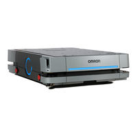
Omron HD-1500 Platform Mobile Robot Manuals
Manuals and User Guides for Omron HD-1500 Platform Mobile Robot. We have
5
Omron HD-1500 Platform Mobile Robot manuals available for free PDF download: User Manual, Assembly Instructions Manual, Safety Manual
Omron HD-1500 Platform User Manual (302 pages)
Brand:
Omron
| Category:
Robotics
| Size: 16 MB
Table of Contents
Intended Audience
3
Units
3
Manual Information
4
Page Structure
4
Special Information
4
Sections in this Manual
7
Table of Contents
8
Terms and Conditions Agreement
14
Warranty and Limitations of Liability
14
Application Considerations
15
Disclaimers
15
Errors and Omissions
16
Safety Precautions
17
Definition of Precautionary Information
17
Symbols
17
Dangers
18
Warnings
18
Operating Environment
22
Cautions
24
Precautions for Safe Use
26
Precautions for Correct Use
29
Regulations and Standards
32
Conformance to EU Directives
32
U.S. / Canada / Industry Standards
32
Conformance to KC Certification
33
Related Manuals
34
Glossary
35
Revision History
38
Overview
39
Intended Use
41
Features and Components
44
Lasers
44
Additional Information
45
Drive Train and Suspension
46
Skins
46
AMR Controller
47
Battery
47
E-STOP Buttons
48
Operator Panel
48
Pendant
49
Light Discs and Strips
50
Speakers
50
Charging Station
51
Charging Contacts
52
User Access Panel
52
Input and Output Control
53
Wireless Antennas
53
Localization Sensors
53
Interlock Switches
53
Electronics Bay
53
Payload Mounting Surface
54
Autonomous Navigation
55
Labels
57
AMR Information Label
57
Docking Target Information Label
58
Power Supply Box Information Label
58
AMR Safety and Warning Label Locations
59
Power Supply Box Safety and Warning Label Locations
60
Docking Target Safety and Warning Label Locations
60
Model Numbers
62
Optional Items
63
Fleet Manager
63
Additional E-STOP Buttons
64
Additional Information
64
Additional Signal Beacons
65
Additional Warning Buzzers
65
Supplementary Laser Scanners
65
Mobile I/O Box
66
High Accuracy Positioning System
66
Cell Alignment Positioning System
66
Top Plate
67
FLOW Core Software
68
Mobileplanner Software
68
System Requirements
69
Fleet Management Software
69
Setnetgo Software
70
Mobilefirmware
71
Driving and Navigation Software
71
Fleet Simulator Software
72
Payload Considerations
73
Payload Structures
74
Exceeding the AMR Footprint
75
Safety Laser Scanner Zone Obstruction
76
Power Consumption
76
Coordinate System
77
Specifications
79
Performance Specifications
80
Physical Specifications
81
Dimensions
81
Weights
85
Payload Center of Gravity
85
Environmental Specifications
88
AMR Environmental Specifications
88
Charging Station Environmental Specifications
88
Battery Environmental Specifications
89
Pendant Environmental Specifications
89
Low Laser/Supplementary Laser Scanner Environmental Specifications
89
Other Specifications
90
Laser Specifications
90
Battery Specifications
90
HAPS Specifications
90
Charging Station Specifications
90
Operator Panel Screen
91
Drive Train
91
Safety Function Performance Levels
91
Stopping Distance and Time
94
Wireless Specifications
95
USER PWR Connector
96
REG PWR Connector
96
SCPU Connector
96
LIGHTS Connector
97
IO 1 Connector
97
Additional Information
97
IO 2 Connector
98
COMMS Connector
98
FTPRT SEL Connector
98
Installation
102
Installation Introduction
103
Charging Station Installation
104
Repositioning the Docking Target Power Connector
105
Mechanical Connections
105
Charging Paddle Alignment
106
Electrical Connections
109
Power Supply Box Commissioning Procedure
112
Battery Removal and Installation
114
Battery Removal Procedure
115
Battery Installation Procedure
116
Network Connections
117
Default Network Settings
117
Wired Connection Procedure
117
Wireless Connection
118
Wireless Considerations
119
Port Forwarding
120
Electrical Connections
121
User Access Panel Connections
121
Attaching the Payload
130
Payload Structure Mounting Points
130
Overhanging Payloads
132
Relocating the Operator Panel
133
HAPS Installation and Configuration
134
Front HAPS Sensor Installation
134
Rear HAPS Sensor Installation
135
Tape and Marker Application
137
Software Configuration
138
Additional Information
138
Goals and Tasks
139
Attaching Warning Labels
142
3-10 Commissioning
143
Commissioning Procedure
143
3-11 Map Creation Overview
144
Basic Mapping Tasks
145
Supplementary Laser Scanner Installation
146
Mounting Considerations
146
Supplementary Laser Scanner Connection Procedure
147
Supplementary Laser Scanner Configuration
148
Operation
151
Payload Movement and Transfer
153
AMR Start-Up
154
AMR Shut-Down
155
AMR Controller LED Indicators
156
Workspace
157
Physical Barriers
159
Logical Barriers
159
Obstacles
160
Environmental Hazards
160
Restricted Zones
160
Operating Hazard Zones
161
Payload Transfer Stations
161
Ramps
162
Additional Information
162
Clearances
164
Rotational Clearances
164
Docking Clearances
164
Narrow Passageway Behavior (Linear)
167
Narrow Passageway Behavior (Non-Linear)
168
U-Turn in a Narrow Passageway
168
U-Turn through a Narrow Doorway
168
4-10 Minimum Lane Width
170
4-11 Immobilization
171
4-12 Battery and Charging
172
Battery Indicators and Controls
173
Charging Station
173
Power Supply Box
174
Operation
175
Charging the Battery
176
Balancing the Battery
179
Storing Batteries
179
4-13 Operator Panel
181
Main Screen
181
Boot-Up Screen
181
ON Button
181
OFF Button
182
Brake Release Button
182
Maintenance Ethernet Port
182
Main Disconnect Switch
183
Pendant Port
183
4-14 Releasing the Brakes
184
4-15 Manually Pushing the AMR
185
4-16 Emergency Stop
186
Additional Information
186
Emergency Stop Recovery Procedure
186
4-17 Protective Stops
188
AMR Response During Protective Stops
188
4-18 Overspeed Protection
189
Light Discs and Optional Beacon States
190
Driving Straight
190
Turn Signal
190
Emergency Stop
190
Lost
190
Stopped
191
Stopped with Warning
191
Obstacle Detected / Protective Stop
191
Charging
191
Booting
192
Operating Inside a Designated Mutepersonneldetectionsector Area
192
Light Strips and Optional Beacon States
193
Driving Straight
193
Turn Signal
193
Emergency Stop
193
Lost
194
Stopped
194
Stopped with Warning
194
Obstacle Detected / Protective Stop
194
Charging
195
Booting
195
Operating Inside a Designated Mutepersonneldetectionsector Area
195
4-21 pendant Operation
197
Driving with the pendant
198
4-22 Warning Buzzer
199
4-23 Back up and Restore the AMR
200
Creating Backup Files
200
Create a Restore-Point
200
Configuration File Backup
201
Restoring the AMR
202
Setnetgo Recovery Mode
207
4-24 Safety Laser Scanner Zones
211
Safety Zone Pairs
211
Alternate Safety Laser Scanner Zones
233
4-25 Motion Limits
234
Additional Information
234
4-26 Emergency Situations
235
4-27 Tilt Detection
236
Tilt Detection Event Recovery
236
4-28 Interlock Switches
237
Collecting Troubleshooting Information
240
Restoring the AMR Configuration
241
Power Supply Box Problems
242
Battery Problems
244
Low Battery Recovery
244
Battery Charging Problems
244
Leaking Batteries
246
Exposure to Liquids
248
AMR Start-Up Problems
249
AMR Shut-Down Problems
250
AMR Controller Errors
251
Operator Panel Information
252
Stop Flags
252
Text Messages
253
Maintenance Introduction
256
Charging Station Lock-Out Tag-Out Procedure
258
AMR Lock-Out Tag-Out Procedure
259
Lifting the AMR
260
Maintenance Items
262
Mechanical Brake Inspection Procedure
262
AMR Charging Contact Inspection
263
Docking Target Inspection
263
Safety and Warning Labels
264
Drive Power Indicator Check Procedure
264
Caster Lubrication Procedure
264
Storing Batteries
266
Cleaning
267
Cleaning Intervals
267
Cleaning AMR Charging Contacts
267
Cleaning the Power Supply Box Cooling Ducts
268
Cleaning Laser Lenses
269
Cleaning Caster Treads
270
Cleaning Drive Wheels
270
Replacing Items
271
Removing and Replacing Skins
271
Light Disc LED Replacement Procedure
275
Light Strip LED Replacement Procedure
277
Operator Panel Replacement / Removal Procedure
278
Wireless Antenna Replacement Procedure
279
AMR Charging Contact Replacement Procedure
280
A-1 Unpacking
284
Advertisement
Omron HD-1500 Platform User Manual (305 pages)
Brand:
Omron
| Category:
Robotics
| Size: 25 MB
Table of Contents
I/O
1
Table of Contents
3
Chapter 1: Introduction
9
Definitions
9
Product Description
10
HD-1500 Autonomous Navigation
12
HD-1500 Localization
12
Custom Payload Structures
12
Body and Drive Train
13
What's Included - Basic Components
14
Optional Features and Components (Partial List)
19
Software Overview
19
HD-1500 Software
19
Setnetgo
23
How Can I Get Help
24
Related Manuals
24
Support
24
Download a Debuginfo File for Support
25
Network Setup
25
Obtain a Debuginfo File from Setnetgo
25
Chapter 2: Safety
27
General Hazards
27
Unprotected Areas
28
What to Do in an Emergency
31
Releasing the Brakes
32
Releasing an E-Stop
33
Dangers, Warnings, and Cautions
34
Alert Levels
34
Alert Icons
34
Special Information
35
User's Responsibilities
37
Electrical Hazards
37
Magnetic Field Hazards
38
Burn Hazard
39
Qualification of Personnel
39
Payload Movement and Transfer
39
Configurable Warning Buzzer
40
Fleet Management
41
Environment
41
General Environmental Conditions
41
Public Access
42
Operating Clearances
42
Obstacles
44
Intended and Non-Intended Use
45
Intended Use
45
Non-Intended Use
46
HD-1500 Platform Modifications
47
Protective Stops Initiated by AMR Safety Lasers
48
Safety System Overspeed Faults
49
Laser Safety
49
Interlock Switches
50
Battery Safety
51
Battery Safety Precautions
52
Battery Maintenance
54
Charging Station
54
Safety Precautions
55
Additional Safety Information
57
Mobile Robot HD Safety Manual (Cat. No. I647)
57
Disposal
57
Chapter 3: Setup
59
Overview of HD-1500 Setup
59
Tasks
59
Transport and Storage
59
HD-1500 Shipping and Storage
59
Battery Crate
60
Power Supply Box, and Docking Target Crates
61
Before Unpacking
62
Unpacking Considerations
62
HD-1500 Unpacking
64
Battery Unpacking
78
Docking Target Unpacking
87
Power Supply Box Unpacking
94
Installing the Battery
103
Installation
103
Attaching the Payload Structure and Options
107
Attach the Payload Structure
107
Attach the no Riding Warning Label
107
Attach HD-1500 Optional Devices
107
E-Stop Jumper on the User Access Panel
108
Warning Buzzer
108
Warning Light
109
Installing the Charging Station
109
Required Tools and Fasteners
110
Charging Station Features and Parts
111
Charging Station Environmental Requirements
114
Power Supply Box Installation
115
Docking Target Installation
119
Chapter 4: Configuration
123
Settings and Configuration
123
Maintenance Ethernet Connection
123
Setting up Wireless Ethernet
126
Create a Workspace Map
129
Map Creation Overview
129
Mapping Tasks
131
Acceleration, Deceleration, and Rotation Limits
131
Supplemental Information
132
Laser Setup
132
Chapter 5: Payload Structures
135
Safety
135
Warning Labels
135
Warning Lights
135
Warning Buzzer
136
Considerations
136
Performance
136
Weight Constraints
136
Power Consumption
137
Power Limits
137
Payload Attachment Location
138
Payload Dimensions and Design
138
Mounting Locations in the Platform
140
AMR Coordinate System
141
Center of Gravity (CG)
142
Payload-Related Tradeoffs
145
Connections between the HD-1500 Platform and Payload Structure
146
Operator Panel on the Payload
146
Optional Connections
147
Chapter 6: Connectivity
149
Required Connections
150
Platform Required Connections
150
Charging Station Required Connections
153
User Access Panel Connections
154
User Pwr
158
Reg Pwr
158
Scpu
160
USER_PROTECTIVE_STOP Input Behavior
161
Lights
162
I/O 1
162
COMMS - RS-232, RS-422, CAN Bus
163
Electronics Bay Connections
164
AMR Controller
165
AMR Controller Connections
167
Ethernet Switches
171
Chapter 7: Operation
177
Operating Environment
177
Intended Use
177
Clearance
177
Obstacles
180
Environment and Floor
180
Getting Stuck (Immobilization Risk)
181
Typical Operation
182
Power and Charging
183
Battery Indicators and Controls
183
Charging Station
184
Safety Precautions
185
Manually Charging the Amr's Battery
190
Balancing the Battery
191
Operator Panel
193
Screen
193
E-Stop Buttons
195
Positioning an Optional Payload E-Stop
196
ON Button
196
OFF Button
196
Brake Release Button
197
Pendant Port
197
Maintenance Ethernet Connection
197
Other Controls and Indicators
198
Light Discs and Beacon
198
Front and Back Light Strips
201
Sensors
206
Lasers
206
Other Sensors
208
Start up
208
Procedure
208
Pendant Controls and Operation Description
208
Chapter 8: Maintenance
213
Safety Considerations When Performing Maintenance
214
Electrical Hazards
214
Electrical Hazard Precautions
214
Burn Hazard
215
ESD Hazards
215
Safety Measures Prior and after Maintenance
215
Lock-Out, Tag-Out Procedure
215
Lifting the Platform Safely
219
Safety Inspection
222
Warning Devices
222
Warning Labels
222
Cleaning
223
Work Area Maintenance
223
Platform and Charging Station Cleaning
223
Maintaining and Replacing Batteries
227
Maintaining Batteries
227
Replacing the Battery
228
Replacing Non-Periodic Parts
237
Light Discs
238
Light Strips
242
Operator Panel
244
Side-Mount Lasers (Side Lasers)
245
Wifi Antennas
248
AMR Charging Contacts
249
E-Stop and Safety Laser Commissioning
251
Removing and Installing Skins
252
Field-Replaceable Periodic Parts
265
Caster and Drive Wheel Treads
265
Caster, Drive Wheel, and Drive Assembly
265
Restoring the Configuration
266
Chapter 9: Options
267
Fleet Manager, for Multi-AMR Coordination
267
Pendant
267
Spare Battery
267
Side-Mount Lasers
267
High-Accuracy Positioning System (HAPS)
267
Charging Station
268
Chapter 10: Technical Specifications
269
Dimension Drawings
269
HD-1500 Platform
269
HD-1500 Charging Station
272
HD-1500 Platform Specifications
273
Physical
273
Performance
274
Sensors
275
HD-1500 Charging Station Specifications
275
Power Supply Box Specifications
275
Docking Target Specifications
276
Omron HD-1500 Platform User Manual (256 pages)
Brand:
Omron
| Category:
Robotics
| Size: 14 MB
Table of Contents
Intended Audience
3
Units
3
Manual Information
4
Page Structure
4
Special Information
4
Sections in this Manual
7
Table of Contents
8
Terms and Conditions Agreement
14
Warranty and Limitations of Liability
14
Application Considerations
15
Disclaimers
15
Safety Precautions
17
Definition of Precautionary Information
17
Symbols
17
Dangers
18
Warnings
18
Cautions
23
Precautions for Safe Use
25
Precautions for Correct Use
28
Regulations and Standards
31
Conformance to EU Directives
31
UL / Canada Standards
31
Conformance to KC Certification
31
Related Manuals
33
Glossary
34
Revision History
37
Overview
39
Intended Use
41
Features and Components
44
Lasers
44
Drive Train and Suspension
45
Skins
46
AMR Controller
47
Battery
47
E-STOP Buttons
48
Operator Panel
48
Pendant
49
Light Strips and Discs
50
Speakers
50
Charging Station
50
Charging Contacts
51
User Access Panel
51
Input and Output Control
52
Wireless Antennas
52
Localization Sensors
52
Interlock Switches
52
Electronics Bay
53
Payload Mounting Surface
53
Autonomous Navigation
54
Information Labels
55
AMR Information Label
55
Docking Target Information Label
55
Power Supply Box Information Label
56
Model Numbers
58
Optional Items
59
EM2100 Fleet Manager
59
Additional E-STOP Buttons
60
Additional Signal Beacons
60
Additional Warning Buzzers
61
Side Lasers
61
Spare Battery
62
High-Accuracy Positioning System
62
Top Plate
63
Software
64
System Requirements
64
ARAM Software
65
Aramcentral Software
65
Mobileplanner Software
66
ARCL Programming Language
67
Integration Toolkit
67
Setnetgo Software
68
Payload Considerations
69
Payload Structures
69
Power Consumption
71
Coordinate System
72
Specifications
73
Performance Specifications
74
Physical Specifications
75
Dimensions
75
Weights
77
Payload Center of Gravity
78
Environmental Specifications
81
AMR Environmental Specifications
81
Charging Station Environmental Specifications
81
Battery Environmental Specifications
81
Pendant Environmental Specifications
82
Laser Specifications
83
Battery Specifications
84
HAPS Specifications
85
Charging Station Specifications
86
Other Specifications
87
Safety Functions
87
Drive Train
89
Operator Panel Screen
89
USER PWR Connector
90
REG PWR Connector
90
SCPU Connector
91
LIGHTS Connector
91
IO 1 Connector
91
IO 2 Connector
92
COMMS Connector
92
Installation Introduction
94
Charging Station Installation
95
Repositioning the Docking Target Power Connector
96
Mechanical Considerations
96
Electrical Considerations
98
Commissioning Procedure
99
Battery Installation Procedure
101
Network Connections
103
Default Network Settings
103
Wired Connection Procedure
103
Wireless Connection
104
Electrical Connections
106
Wireless Antenna Connections
106
User Access Panel Connections
107
Attaching the Payload
115
Payload Structure Mounting Points
115
Overhanging Payloads
117
Relocating the Operator Panel
118
Side Laser Relocation to the Payload Structure
119
Side Laser Removal from the AMR
119
HAPS Installation and Configuration
122
Tape and Marker Application
122
Software Configuration
123
Goals and Tasks
124
3-10 Attaching Warning Labels
127
3-11 Safety Commissioning
128
Safety Commissioning Procedure
128
3-12 Map Creation Overview
129
Basic Mapping Tasks
130
Operation
131
Payload Movement and Transfer
133
AMR Start-Up
134
AMR Shut-Down
135
AMR Controller LED Indicators
136
Workspace
137
Physical Barriers
138
Logical Barriers
139
Obstacles
139
Environmental Hazards
139
Restricted Zones
140
Operating Hazard Zones
140
Confined Zones
140
Payload Transfer Stations
140
Clearances
141
Rotational Clearances
141
Docking Clearances
141
Narrow Passageway Behavior (Linear)
143
Narrow Passageway Behavior (Non-Linear)
144
U-Turn in a Narrow Passageway
144
U-Turn through a Narrow Doorway
144
Minimum Lane Width
146
4-10 Immobilization
147
4-11 Battery and Charging
148
Battery Indicators and Controls
148
Removing the Battery
149
Charging Station
151
Charging the Battery
153
Balancing the Battery
155
Storing Batteries
156
4-12 Operator Panel
157
Main Screen
157
ON Button
157
OFF Button
158
Brake Release Button
158
Maintenance Ethernet Port
158
Main Disconnect Switch
159
Pendant Port
159
4-13 Releasing the Brakes
160
4-14 Manually Pushing the AMR
161
4-15 Emergency Stop
162
Emergency Stop Recovery Procedure
162
4-16 Protective Stops
164
AMR Response During Protective Stops
164
4-17 Overspeed Protection
165
Light Discs and Optional Beacon States
166
Driving Straight
166
Turn Signal
166
Emergency Stop
166
Lost
166
Stopped or Booting
167
Stopped with Warning
167
Obstacle Detected
167
Charging
167
Light Strips and Optional Beacon States
169
Driving Straight
169
Turn Signal
169
Emergency Stop
169
Lost
170
Stopped or Booting
170
Stopped with Warning
170
Obstacle Detected
170
Charging
171
4-20 Pendant Operation
172
Driving with the Pendant
172
4-21 Warning Buzzer
174
4-22 Safety Laser Scanner Zones
175
Safety Zone Pairs
175
4-23 Wireless Considerations
188
Signal Availability
188
Bandwidth
188
Port Forwarding
188
4-24 Motion Limits
189
4-25 Emergency Situations
190
4-26 Tilt Detection
191
4-27 Interlock Switches
192
Collecting Troubleshooting Information
194
Restoring the Default Configuration
195
Power Supply Box Problems
196
Battery Problems
198
Low Battery Recovery
198
Battery Charging Problems
198
Leaking Batteries
199
Exposure to Liquids
201
AMR Start-Up Problems
202
AMR Controller Errors
203
Operator Panel Information
204
Stop Flags
204
Text Messages
205
Maintenance Introduction
208
AMR Lock-Out Tag-Out Procedure
210
Charging Station Lock-Out Tag-Out Procedure
211
Lifting the AMR
212
Drive Power Indicator Check Procedure
214
Inspection Intervals
215
Mechanical Brake Inspection Procedure
215
AMR Charging Contact Inspection
216
Docking Target Charging Contacts Inspection
216
Safety and Warning Labels
216
Stored Batteries
219
Cleaning
220
Cleaning Intervals
220
Cleaning AMR Charging Contacts
220
Cleaning the Power Supply Box Cooling Ducts
221
Cleaning Lasers Lenses
222
Cleaning Caster Treads
222
Cleaning Drive Wheels
222
Replacing Items
224
Removing and Replacing Skins
224
Light Disc LED Replacement Procedure
228
Light Strip LED Replacement Procedure
230
Operator Panel Replacement / Removal Procedure
231
Wireless Antenna Replacement Procedure
232
AMR Charging Contact Replacement Procedure
233
Advertisement
Omron HD-1500 Platform Assembly Instructions Manual (104 pages)
Brand:
Omron
| Category:
Robotics
| Size: 3 MB
Table of Contents
Intended Audience
3
Units
3
Manual Information
4
Page Structure
4
Special Information
5
Sections in this Manual
7
Table of Contents
8
Terms and Conditions Agreement
11
Warranty and Limitations of Liability
11
Application Considerations
12
Disclaimers
12
Safety Precautions
14
Definition of Precautionary Information
14
Symbols
14
Dangers
15
Warnings
15
Cautions
17
Precautions for Safe Use
19
Precautions for Correct Use
22
Regulations and Standards
25
Conformance to EU Directives
25
Related Manuals
28
Glossary
29
Revision History
32
Overview
33
Assembly Instructions
34
Intended Use
35
Features and Components
38
Lasers
38
Skins
39
AMR Controller
39
Battery
40
E-Stop Buttons
40
Operator Panel
41
Pendant
42
Light Strips and Discs
42
Speakers
42
User Access Panel
43
Wireless Antennas
43
Interlock Switches
44
Electronics Bay
44
Payload Mounting Surface
44
Autonomous Navigation
45
Optional Items
47
EM2100 Fleet Manager
47
Additional E-Stop Buttons
47
Additional Warning Lights
48
Additional Warning Buzzers
49
Top Plate
49
Software
50
System Requirements
50
Payload Considerations
52
Payload Structures
52
Coordinate System
55
Specifications
57
Performance Specifications
58
Physical Specifications
59
Dimensions
59
Weights
60
Payload Center of Gravity
60
Environmental Specifications
64
AMR Environmental Specifications
64
Battery Environmental Specifications
64
Pendant Environmental Specifications
65
Laser Specifications
66
Battery Specifications
67
Other Specifications
68
Safety Functions
68
USER PWR Connector
70
REG PWR Connector
71
SCPU Connector
71
LIGHTS Connector
72
IO 1 Connector
72
IO 2 Connector
72
COMMS Connector
73
Installation
75
Installation Introduction
76
Battery Installation Procedure
77
Network Connections
79
Default Network Settings
79
Wired Connection Procedure
79
Wireless Connection
80
Electrical Connections
82
Wireless Antenna Connections
82
User Access Panel Connections
83
Attaching the Payload
91
Payload Structure Mounting Points
91
Attaching Warning Labels
94
Safety Commissioning
95
Safety Commissioning Procedure
95
Operation
97
Omron HD-1500 Platform Safety Manual (70 pages)
Mobile Robot
Brand:
Omron
| Category:
Robotics
| Size: 3 MB
Table of Contents
Table of Contents
5
Chapter 1: Alerts and Special Information
7
Alert Levels
7
Alert Icons
7
Falling Hazards
8
Special Information
9
Chapter 2: Operational Safety
11
Definitions
11
General Hazards
11
Unprotected Areas
13
What to Do in an Emergency
16
Releasing the Brakes
17
Releasing an E-Stop
19
User's Responsibilities
20
Electrical Hazards
21
Magnetic Field Hazards
21
Burn Hazard
22
Qualification of Personnel
22
Payload Movement and Transfer
23
Configurable Warning Buzzer
23
Speakers
24
Mechanical Brakes
24
Fleet Management
25
Other Hazards
26
Risk Assessment
26
Exposure
26
Severity of Injury
26
Obstacle Avoidance
26
Safety System Behavior
27
Environment
27
General Environmental Conditions
27
Public Access
28
Operating Clearances
28
Obstacles
30
Intended and Non-Intended Use
31
Intended Use
31
Non-Intended Use
31
HD-1500 Platform Modifications
33
Safety Considerations When Performing Maintenance
33
Electrical Hazards
34
Electrical Hazard Precautions
34
Burn Hazard
34
ESD Hazards
35
Safety Measures Prior and after Maintenance
35
Lock-Out, Tag-Out Procedure
35
Safety Inspection
39
Safety and Warning Devices
39
Warning Labels
40
Protective Stops Initiated by AMR Safety Lasers
41
Safety System Overspeed Faults
42
Laser Safety
42
Interlock Switches
44
Battery Safety
45
Battery Safety Precautions
46
Battery Maintenance
48
Charging Station
48
Safety Precautions
49
Payload Structure
53
Safety
54
Considerations
55
Additional Safety Information
63
Mobile Robot HD Safety Manual (Cat. No. I647)
64
Additional Safety Information
64
Disposal
64
Advertisement
Related Products
Omron Heavy Payload Series
Omron HD
Omron HD Series
Omron AUTOMATIC DIGITAL HEM-739
Omron HEM-711AC
Omron H3CR-A8
Omron H7ET-NV-BH
Omron H3DR-G
Omron H3CA
Omron H7BR-BW
Omron Categories
Blood Pressure Monitor
Controller
Accessories
Switch
Inverter
More Omron Manuals
Login
Sign In
OR
Sign in with Facebook
Sign in with Google
Upload manual
Upload from disk
Upload from URL