Table of Contents
Advertisement
Quick Links
This user's guide describes the functionality, hardware, operation, and software instructions to implement
the High Speed Data Converter Pro Graphic User Interface (HSDC Pro GUI) with the KCU105, a Xilinx
Kintex
UltraScale™ field-programmable gate array (FPGA) evaluation kit.
®
...................................................................................................................
1
2
3
3.1
3.2
3.3
4
4.1
4.2
5
6
6.1
6.2
6.3
6.4
7
7.1
7.2
7.3
7.4
7.5
7.6
8
1
2
3
4
5
6
7
8
9
10
11
12
13
14
SLAU711 - March 2017
Submit Documentation Feedback
..................................................................................................................
..........................................................................................................
.....................................................................................................
®
..................................................................................
.....................................................................................................
...........................................................................................................
......................................................................................................
..........................................................................................
......................................................................................
.........................................................................................
..............................................................................................
....................................................................................
....................................................................................................
...........................................................................................................
.....................................................................................
....................................................................................
2016.3
®
........................................................................................
........................................................................................
....................................................................................
......................................................................................
.......................................................................................
......................................................................................
......................................................................................
.................................................................................
......................................................................................
Copyright © 2017, Texas Instruments Incorporated
HSDC Pro With Xilinx
Contents
®
.......................................................................
........................................................
.....................................................
.....................................................
........................................................
......................................................
.....................................................
List of Figures
..............................................................................
...............................................................................
........................................................................
User's Guide
SLAU711 - March 2017
®
KCU105
...................
HSDC Pro With Xilinx
®
KCU105
®
3
3
3
3
3
3
4
4
4
5
6
6
7
8
8
10
10
15
18
22
25
27
35
6
7
8
9
9
10
11
12
12
13
14
15
16
17
1
Advertisement
Table of Contents

Related Manuals for Texas Instruments KCU105


Summary of Contents for Texas Instruments KCU105
-
Page 1: Table Of Contents
® KCU105 This user's guide describes the functionality, hardware, operation, and software instructions to implement the High Speed Data Converter Pro Graphic User Interface (HSDC Pro GUI) with the KCU105, a Xilinx ® Kintex UltraScale™ field-programmable gate array (FPGA) evaluation kit. - Page 2 UltraScale is a trademark of Xilinx Incorporated. Xilinx, Kintex, Vivado are registered trademarks of Xilinx Incorporated. All other trademarks are the property of their respective owners. HSDC Pro With Xilinx ® KCU105 SLAU711 – March 2017 Submit Documentation Feedback Copyright © 2017, Texas Instruments Incorporated...
-
Page 3: Introduction
KCU105 uses Ethernet and dual USB-to-UART capabilities to interface with a host computer and set up the FPGA. Texas Instruments has created a platform where the KCU105 can interface with TI’s latest and most popular JESD204B-based high speed data converter evaluation modules (EVM) as if it were connected to a TI development board. -
Page 4: Required Software
Vivado 2016.3. Serial Terminal Emulator A serial terminal emulator is required to establish a serial port connection through the KCU105 dual UART interface. Any sort of serial terminal software, such as TeraTerm, PuTTY, or Hercules, can be used. For this user's guide, TeraTerm is used as the main terminal emulator. -
Page 5: Dac And Adc Gui Configuration File Changes When Using A Xilinx
10, 20, and 40. Therefore, the possible values for REFCLK are: 5.0G / 10 = 500 MHz, 5.0G / 20 = 250 MHz, 5.0G / 40 = 125 MHz SLAU711 – March 2017 HSDC Pro With Xilinx ® KCU105 Submit Documentation Feedback Copyright © 2017, Texas Instruments Incorporated... -
Page 6: Kcu105 Quick Start-Up Instructions
Standard COM Port. Ensure the baud rate of this serial connection is "9600", leaving all other defaults as set. 8. Connect an Ethernet cord from the KCU105 to a port such as an Ethernet switch or router that is in the same local network as the host computer. Other Ethernet interfaces are shown in the UltraScale Hardware Demonstration user guide on Xilinx.com. -
Page 7: Programing The Fpga
7. Select the proper bit stream file. The firmware is found in: “C:\Program Files (x86)\Texas Instruments\High Speed Data Converter Pro\KCU105 Details\Firmware\KCU105_TI_DHCP.bit". NOTE: If there is an error regarding ASCII characters, drag the bit file to the desktop and target the file there. -
Page 8: Adjusting Fpga Fmc Settings
1. Open the HSDC Pro GUI as administrator. 2. In the "Select Board" pop up, check "Connect to KCU105". Enter the IP address followed by a colon and port number. There is also an option to select from the drop-down menu. Both IP address and port number can be found in the Standard COM port terminal. -
Page 9: Ip Address In Standard Com Port
Copyright © 2017, Texas Instruments Incorporated Figure 4. IP Address in Standard COM Port Figure 5 is a screenshot of HSDC Pro connecting to the KCU105. Copyright © 2017, Texas Instruments Incorporated Figure 5. HSDC Pro Connecting to KCU105 SLAU711 – March 2017 HSDC Pro With Xilinx ®... -
Page 10: Board Setup Examples
Board Setup Examples This section provides examples using the Xilinx KCU105 development platform with various JESD204B TI EVMs. Based on the EVM, the example will show what needs to be modified in order for the integration to work. The instructions in Section 6 must be completed before continuing with the following examples. -
Page 11: Dac38J84Evm Gui Configuration
(d) Interpolation – "2" Figure 7 is a screenshot of a configured GUI for a DAC38J84EVM 8411 JESD204B mode. Copyright © 2017, Texas Instruments Incorporated Figure 7. DAC38J84EVM GUI Configuration 3. Press the 1. Program LMK04828 and DAC3XJ8X button. 4. Open HSDC Pro, press on the DAC tab, and select "DAX3XJ84_LMF_841" from the drop-down menu. -
Page 12: Generating A Tone With Hsdc Pro Gui
Board Setup Examples www.ti.com Copyright © 2017, Texas Instruments Incorporated Figure 8. Generating a Tone With HSDC Pro GUI 6. Click the Create Tones button and press the Send button. 7. The new lane rate (12.288 GHz) and FPGA Clock (307.2 MHz) settings should be shown. -
Page 13: Dac38J84Evm Gui Configuration
(b) DAC Data Input Rate – "368.64" MSPS (c) Number of SerDes Lanes per DAC – "8" (d) Interpolation – "4" Copyright © 2017, Texas Instruments Incorporated Figure 10. DAC38J84EVM GUI Configuration SLAU711 – March 2017 HSDC Pro With Xilinx ®... -
Page 14: Dac38J84Evm Gui Dclk Divider
From the GUI, navigate to the LMK04828 Controls tab. Under Clock Outputs, update the DCLK Divider to "16" in the DAC GUI as shown in Figure Copyright © 2017, Texas Instruments Incorporated Figure 11. DAC38J84EVM GUI DCLK Divider Follow the procedure in Section 7.1... -
Page 15: Adc12J4000Evm With Kcu105 Board Setup Example
Board Setup Examples www.ti.com ADC12J4000EVM With KCU105 Board Setup Example The following section provides an example testing the ADC12J4000EVM in bypass mode using a KCU105 development platform. NOTE: There is a jumper "KC705 JTAG" on the ADC12J4000EVM that will prevent the firmware from downloading if it is not shunted. -
Page 16: Configured Adc12J4000Evm Gui
Decimation and Serial Data Mode to "Bypass Mode; DDR". 4. Click Program Clocks and ADC. Figure 13 shows a screenshot of the configured GUI. Copyright © 2017, Texas Instruments Incorporated Figure 13. Configured ADC12J4000EVM GUI HSDC Pro With Xilinx ®... -
Page 17: Hsdc Pro Adc12J4000Evm Captured Result
7. Click the Capture button, and the new line rate (8G) and JESD reference clock (200M) should show. Figure 14 shows a captured result sending a 170-MHz single tone through Vin at –1 dBFS. Copyright © 2017, Texas Instruments Incorporated Figure 14. HSDC Pro ADC12J4000EVM Captured Result SLAU711 – March 2017 HSDC Pro With Xilinx ®... -
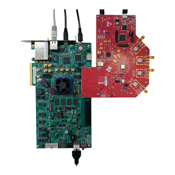
Page 18: Adc32Rf45Evm With Kcu105 Board Setup Example
Bypass mode. Make sure the instructions in Section 6 are completed before testing the EVM. Figure 15 shows a setup between the ADC32RF45EVM and KCU105. Copyright © 2017, Texas Instruments Incorporated Figure 15. ADC32RF45EVM Setup With KCU105 HSDC Pro With Xilinx ®... -
Page 19: Adc32Rf45Evm Gui Quick Setup
(a) Clock Source to ADC – "External Clocking" (b) ADC32RF45 Mode – "Bypass" (c) BYPASS – "14 bit" Copyright © 2017, Texas Instruments Incorporated Figure 16. ADC32RF45EVM GUI Quick Setup 5. Click on PROGRAM EVM. 6. Go to the Clock Outputs tab under the LMK04828 tab. -
Page 20: Adc32Rfevm Gui Clock Outputs
Board Setup Examples www.ti.com Copyright © 2017, Texas Instruments Incorporated Figure 17. ADC32RFEVM GUI Clock Outputs 8. Click on the SYSREF and SYNC tab. Verify the SYSREF Divider is set to "1024". 9. In the ADC Configuration tab under ADC32RFxx, set the JESD204b Lane De-emphasis setting to "0"... -
Page 21: Adc32Rf45Evm Capture On Hsdc Pro
Figure 19 shows a captured result sending a 170-MHz single tone through Vin at –2 dBFS to AINP (J2). Copyright © 2017, Texas Instruments Incorporated Figure 19. ADC32RF45EVM Capture on HSDC Pro SLAU711 – March 2017 HSDC Pro With Xilinx ®... -
Page 22: Ads54J20Evm With Kcu105 Board Setup Example
ADS54J20EVM With KCU105 Board Setup Example The following section provides an example testing the ADS54J20EVM in 8224 mode with the KCU105 development platform. EVMs in the same family, such as the ADS54J40EVM and ADS54J60EVM, can be configured with the same instructions and proper configuration files. Make sure the instructions in Section 6 are completed before testing the EVM. -
Page 23: Configuration Files For Ads54J20Evm Gui
3. On the Low Level View tab, load the following configuration files: "LMK_983p04_8224_VC707.cfg" as shown in Figure Copyright © 2017, Texas Instruments Incorporated Figure 21. Configuration Files for ADS54J20EVM GUI 4. Press the ADC RESET button (SW1) on the EVM to provide a hardware reset to the ADC 5. -
Page 24: Hsdc Pro Ads43J20Evm Captured Result
9. Click on OK. Click the Capture button. Figure 22 shows a captured result sending a 170-MHz single tone through Vin at –1 dBFS. Copyright © 2017, Texas Instruments Incorporated Figure 22. HSDC Pro ADS43J20EVM Captured Result HSDC Pro With Xilinx ®... -
Page 25: Ads42Jb49Evm With Kcu105 Board Setup Example
ADS42JB49EVM With KCU105 Board Setup Example The following section provides an example testing the ADS42JB49EVM in 421 mode with the KCU105 development platform. EVMs in the same family, such as the ADS42JB69EVM, can be configured with the same instructions and proper configuration files. Make sure the instructions in... -
Page 26: Hsdc Pro Ads42Jb49Evm Captured Result
9. Click the Capture button. Figure 24 shows a captured result sending a 80-MHz single tone through Vin at –1 dBFS. Copyright © 2017, Texas Instruments Incorporated Figure 24. HSDC Pro ADS42JB49EVM Captured Result HSDC Pro With Xilinx ® KCU105 SLAU711 –... -
Page 27: Dac38Rf82Evm With Kcu105 Board Setup Example
DAC38RF82EVM With KCU105 Board Setup Example The following section provides an example of testing the DAC38RF82EVM using a KCU105 development platform. With the updated firmware, users can use the DAC38RFXX GUI as if it was connected to a TI TSW14J56. -
Page 28: Dac38Rfxx Evm Gui In External Clock Mode
Core & SYSREF TRIGGER button. 7. Navigate to the LMK04828 tab. Change the DCLK Divider on CLKout 0 and 1 to "8" as shown in Figure 27. This will provide the right reference clock to send to the KCU105. HSDC Pro With Xilinx ®... -
Page 29: Dac38Rf82Evm Gui Dclk Divider
Board Setup Examples www.ti.com Copyright © 2017, Texas Instruments Incorporated Figure 27. DAC38RF82EVM GUI DCLK Divider 8. Open HSDC Pro, press the DAC tab, and select "DAX38RF8X_LMF_841" from the drop-down menu. 9. Enter "375M" as the Data Rate (SPS)and change the DAC Option to "2’s Complement". Make sure the number of samples is set to at least 8192, but do not exceed 32,768. -
Page 30: Analog Output From Dac38Rf82Evm
13. Connect channel one of the DAC38RF82EVM (J6) to a spectrum analyzer and verify the signal. Figure 29 shows the analog output generated by the DAC38RF82EVM Copyright © 2017, Texas Instruments Incorporated Figure 29. Analog Output From DAC38RF82EVM HSDC Pro With Xilinx ®... -
Page 31: Dac38Rfxx Evm Gui In Pll Mode
(f) # of serdes lanes per DAC – "4 Lanes" (g) Desired Interpolation – "18x" Copyright © 2017, Texas Instruments Incorporated Figure 30. DAC38RFXX EVM GUI in PLL Mode 6. Press the CONFIGURE DAC button, followed by the PLL AUTO TUNE button, then the Reset DAC JESD Core &... -
Page 32: Dac38Rf82Evm Gui Nco Frequency Settings
8. Click the UPDATE NCO button. Go back to the Quick Start tab and press Reset DAC JESD Core & SYSREF TRIGGER button. This can also be done on the Digital(DAC B) tab, which will provide an NCO Frequency on channel B. Copyright © 2017, Texas Instruments Incorporated Figure 31. DAC38RF82EVM GUI NCO Frequency Settings HSDC Pro With Xilinx ®... -
Page 33: Hsdc Pro Configuration For Pll Mode
(d) Tone selection – "Complex" Figure 32 is a screenshot of a proper configuration on HSDC Pro. Copyright © 2017, Texas Instruments Incorporated Figure 32. HSDC Pro Configuration for PLL Mode 12. Click the Create Tones button and press Send. -
Page 34: Analog Output From Dac38Rf82Evm
15. Connect channel one of the DAC38RF82EVM (J6) to a spectrum analyzer and verify the signal. Figure 33 shows the analog output generated by the DAC38RF82EVM. Copyright © 2017, Texas Instruments Incorporated Figure 33. Analog Output From DAC38RF82EVM HSDC Pro With Xilinx ®... -
Page 35: Eyescan Analysis
Eyescan Analysis One of the features of the KCU105 is the ability to receive data and measure the horizontal and vertical eye opening. This Eyescan feature is used as an diagnosis tool to debug the digital signals in each enabled lane. - Page 36 STANDARD TERMS FOR EVALUATION MODULES Delivery: TI delivers TI evaluation boards, kits, or modules, including any accompanying demonstration software, components, and/or documentation which may be provided together or separately (collectively, an “EVM” or “EVMs”) to the User (“User”) in accordance with the terms set forth herein.
- Page 37 FCC Interference Statement for Class B EVM devices NOTE: This equipment has been tested and found to comply with the limits for a Class B digital device, pursuant to part 15 of the FCC Rules. These limits are designed to provide reasonable protection against harmful interference in a residential installation.
- Page 38 【無線電波を送信する製品の開発キットをお使いになる際の注意事項】 開発キットの中には技術基準適合証明を受けて いないものがあります。 技術適合証明を受けていないもののご使用に際しては、電波法遵守のため、以下のいずれかの 措置を取っていただく必要がありますのでご注意ください。 1. 電波法施行規則第6条第1項第1号に基づく平成18年3月28日総務省告示第173号で定められた電波暗室等の試験設備でご使用 いただく。 2. 実験局の免許を取得後ご使用いただく。 3. 技術基準適合証明を取得後ご使用いただく。 なお、本製品は、上記の「ご使用にあたっての注意」を譲渡先、移転先に通知しない限り、譲渡、移転できないものとします。 上記を遵守頂けない場合は、電波法の罰則が適用される可能性があることをご留意ください。 日本テキサス・イ ンスツルメンツ株式会社 東京都新宿区西新宿6丁目24番1号 西新宿三井ビル 3.3.3 Notice for EVMs for Power Line Communication: Please see http://www.tij.co.jp/lsds/ti_ja/general/eStore/notice_02.page 電力線搬送波通信についての開発キットをお使いになる際の注意事項については、次のところをご覧ください。http:/ /www.tij.co.jp/lsds/ti_ja/general/eStore/notice_02.page 3.4 European Union 3.4.1 For EVMs subject to EU Directive 2014/30/EU (Electromagnetic Compatibility Directive): This is a class A product intended for use in environments other than domestic environments that are connected to a low-voltage power-supply network that supplies buildings used for domestic purposes.
- Page 39 Notwithstanding the foregoing, any judgment may be enforced in any United States or foreign court, and TI may seek injunctive relief in any United States or foreign court. Mailing Address: Texas Instruments, Post Office Box 655303, Dallas, Texas 75265 Copyright © 2017, Texas Instruments Incorporated...
- Page 40 IMPORTANT NOTICE FOR TI DESIGN INFORMATION AND RESOURCES Texas Instruments Incorporated (‘TI”) technical, application or other design advice, services or information, including, but not limited to, reference designs and materials relating to evaluation modules, (collectively, “TI Resources”) are intended to assist designers who are developing applications that incorporate TI products;...
Need help?
Do you have a question about the KCU105 and is the answer not in the manual?
Questions and answers