Table of Contents
Advertisement
Advertisement
Table of Contents

Related Manuals for Raven SCS 661


Summary of Contents for Raven SCS 661
- Page 1 SCS 661 FOR LIQUID AND GRANULAR APPLICATIONS INSTALLATION SERVICE MANUAL...
- Page 2 W A R N I N G Disconnect console before jump starting, charging battery, or welding on equipment.
- Page 5 Bring the defective part, and proof of date of purchase, to your local dealer. If your dealer agrees with the warranty claim, he will send the part, and proof of purchase to his distributor or to Raven for final approval. WHAT WILL RAVEN INDUSTRIES DO? When our inspection proves the warranty claim, we will, at our option, repair or replace the defective part and pay for return freight.
- Page 6 Manual Rev. D, SCS 661, LIQ. 07/02 #016-0159-744...
-
Page 7: Table Of Contents
07/02 SYMBOL DEFINITION ......................3 INTRODUCTION ........................5 INSTALLATION ........................6 1. MOUNTING THE RAVEN RADAR SPEED SENSOR ........... 6 2. MOUNTING THE FLOW METER ................... 7 3. MOUNTING THE CONTROL VALVE ................7 4. MOUNTING THE ENCODER ..................8 5. - Page 8 5. FAN RPM SENSOR INSTALLATION ................44 6. BIN LEVEL SENSOR INSTALLATION ................45 7. SERIAL INTERFACE ......................46 8. SCS 661 COMMUNICATION STRINGS ................47 9. VERIFICATION OF SPREADER CONSTANT ..............48 10. WHEEL DRIVE SPEED SENSOR INSTALLATION & CALIBRATION PROCEDURE ..49 11.
-
Page 9: Symbol Definition
SYMBOL DEFINITION (Liquid Applications) - Gallons per minute - Centimeters lit/min - Liters per minute - Decimeters dl/min - Deciliter per minute - Meter - Pounds per square inch - Miles per hour - Kilopascal - Kilometers - Gallon per acre km/h - Kilometers per hour lit/ha... - Page 10 SYMBOL DEFINITION (Granular Application) - Kilometers - Pounds per minute km/h - Kilometers per hour kg/min - Kilograms per minute - Volume per acre - Pounds per acre - Volume per hectare kg/ha - Kilograms per hectare - Volume per 1,000 sq. ft. - Pounds per 1,000 sq.
-
Page 11: Introduction
This manual provides a simple step-by-step procedure for installing and operating. The SCS 661 liquid system consists of a Control Console, a Speed Sensor, a turbine type Flow Meter, and a motorized Control Valve. The SCS 661 granular system consists of a Control Console, a Speed Sensor, an Encoder, and a Hydraulic Control Valve. -
Page 12: Installation
INSTALLATION MOUNTING THE RAVEN RADAR SPEED SENSOR For mounting the radar, the following guidelines will assure proper installation: It is suggested that a large heavy mounting bracket, (P/N 107-0159-693) be attached to the vehicle frame for mounting the radar. Park vehicle on level surface. -
Page 13: Mounting The Flow Meter
MOUNTING THE FLOW METER (Liquid Applications) Mount Flow Meter in the area of the boom valves per Figure 4. All flow through Flow Meter must go to booms only, i.e., no return line to tank or pump after Flow Meter. Mount Flow Meter horizontal to the ground. -
Page 14: Mounting The Encoder
MOUNTING THE ENCODER (Granular Applications) Mount Encoder on output shaft of conveyor, or other shaft which rotates at a known ratio to the conveyor. (See Figures 6,7, 8 & 9). Apply grease to Encoder shaft, conveyor shaft, and Encoder coupler (fits 1" diameter conveyor shaft). -
Page 15: Mounting The Hydraulic Control Valve
MOUNTING THE HYDRAULIC CONTROL VALVE (Granular Applications) Refer to Figures 6,7, 8 & 9 for typical placement of the Hydraulic Control Valve. Valve is to be mounted with motor in the upright position. SPINNER SYSTEM OPEN HYDRAULIC SYSTEM (FIXED DISP. PUMP) CLOSED HYDRAULIC SYSTEM (VARIABLE DISP. -
Page 16: Mounting The Console And Cabling
MOUNTING THE CONSOLE AND CABLING Mount the Console and Switch Box to a secure support inside the cab of the vehicle. Connect the Console Control Cable to the plug in the back of the Console. (See Figure 10). Route the Console Control Cable out of the vehicle cab and connect with vehicle connectors. FIGURE 10 Secure Console Control Cable with plastic cable ties. -
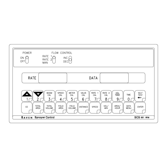
Page 17: Console Features
CONSOLE FEATURES IMPORTANT: This Console requires selection of US (acres), SI [hectares], or TU {1,000 sq. ft.} area; SP1 (wheel drive, etc.) or SP2 (radar) speed sensor; LI (liquid sprayer), GR1 (single belt bed), GR2 (split belt bed), or GR3 (split belt bed, dual encoder); C-Sd (Standard Valve), C-F (Fast Valve), C-FC (Fast Close Valve), and C-P (PWM Valve). -
Page 18: Console Calibration
CONSOLE CALIBRATION CALCULATING “BOOM CAL” Calculate the width of each boom in inches (cm) by multiplying the number of tips time the spacing. Write these boom widths down for future reference when programming the Console. BOOM CALIBRATION Definition of Boom Calibration keys for a Boom system. Depressing this key, displays selected boom number in DATA display. -
Page 19: Calculating "Speed Cal
CALCULATING "SPEED CAL" Initial SPEED CAL is 598 [152]. Complete Steps 1 thru 6 to refine this number after "INITIAL CONSOLE PROGRAMMING" has been completed. Set POWER switches to ON, all other switches to OFF. Enter "0" in key labelled: Drive 1 mile [1 kilometer]. -
Page 20: Calculating "Spreader Constant
CALCULATING "SPREADER CONSTANT" (Granular Appli- cations) For RATE displayed in 1 lb [1 kg] increments: = Length in inches [centimeters], of belt travel per 1 revolution of Sensor = Gate Height in inches [centimeters] = Gate Width in inches [centimeters] = Counts per 1 revolution of sensor English (US) : Metric (SI):... -
Page 21: Calculating "Valve Cal
CALCULATING "VALVE CAL" The initial Control Valve calibration number for VALVE CAL is 2123 for C-Sd (standard valve), 743 for C-F (fast valve) and C-FC (fast close valve) or 43 for C-P (PWM Valve). The VALVE CAL number is used to control response time of the Motor Control to the change in vehicle speed. After operating the system, you may desire to refine this number. -
Page 22: Calculating "Rate 1 And Rate 2 Cal
CALCULATING "RATE 1 AND RATE 2 CAL" LIQUID APPLICATIONS Determine the application rate at which your chemical should be sprayed. Consult with your Dealer to ensure your spray nozzles are capable of applying at this rate. In determining which spray nozzles to use with your sprayer, you must know: 1) Nominal Application Pressure ___ PSI [kpa]... - Page 23 GRANULAR APPLICATIONS The application rate in lbs/acre [kg/ha] is entered as RATE CAL. Consult the equipment manual to insure that the selected gate opening is capable of applying at this application rate. NOTE: The Spreader Constant must be recalculated anytime the gate opening is changed.
-
Page 24: Console Programming
CONSOLE PROGRAMMING When entering data into the Console, the entry sequence is always the same. NOTE: DATA MUST BE ENTERED IN KEYS 3 THRU 8. Depress the key in which Depress the ENTER key. An "E" you wish to enter data. will illuminate in the DATA display. -
Page 25: Initial Console Programming
INITIAL CONSOLE PROGRAMMING When you first turn on Console power, after all installation procedures have been completed, the Console will flash "CAL" in the RATE display. This means you must "calibrate", or program, the Console before it can be operated. This is a onetime operation which does not have to be repeated. Turning OFF the POWER ON/OFF switch does not affect the Console memory. - Page 26 Depressing momentarily steps the DATA display from GR3 to LI. Selecting LI, GR1, GR2, OR GR3. To select LI step until desired code is displayed in the DATA display. Momentarily depress , the data display will now display C-Sd. Displaying C-Sd (Standard Valve), C-F (Fast Valve), or C-FC (Fast Close Valve) or C-P (PWM Valve).
- Page 27 Enter SPEED CAL calibration number in key labelled Enter the METER CAL. For a liquid system, enter the METER CAL calibration number in key labelled . For a granular system, follow steps a and b. Depress and hold key for 5 seconds. When DATA display flashes "0", enter the Spreader Constant as calculated under "CALCULATING SPREADER CONSTANT".
- Page 28 ENTERING TIME, DATE, AND POWER DOWN: Definition of Time, Date, and Power Down Key: Depressing this key displays selected Time features in DATA display. EXAMPLE: RATE display will display "TInE" and DATA will display 0:00. Depressing this key after selecting TIME toggles up through desired features. EXAMPLE: TIME, MONTH, DAY, YEAR, and POWER DOWN.
-
Page 29: Other Display Features
OTHER DISPLAY FEATURES To display TOTAL AREA covered, momentarily depress key labelled To "zero out" this total at any time, enter a "0" in this key. To display TOTAL VOLUME applied, momentarily depress key labelled To "zero out" this total at any time, enter a "0" in this key. To display FIELD AREA covered, momentarily depress key labelled To "zero out"... -
Page 30: Volume/Minute Rate Fault
VOLUME/MINUTE RATE FAULT Depress until DATA display flashes. A low limit flow rate may now be entered. If the actual volume per minute falls below this limit, the Control Valve stops closing, an alarm sounds, and the display flashes "-LL-". The low limit value should be determined with all booms ON. This value is automatically proportional to the percentage of booms that are ON. -
Page 31: Control Valve Delay
CONTROL VALVE DELAY Depress until DATA display flashes. The first digit, ( X 0 0 0 ), is the Control Valve delay digit. This feature allows the user to set a delay between the time the booms are turned ON and when the Console begins to control the flow rate. -
Page 32: 12. Data Menu
12. DATA MENU The following are brief descriptions of features available under the DATA MENU key: DISPLAY RATE DATA FEATURE and DESCRIPTION bEGn CONSOLE DATA PRINTOUT Sends data through serial port to attached optional printer to print field begin and field end pages. ALrn AUDIBLE ALARMS ON/OFF Turns audible alarms ON or OFF for the following:... - Page 33 RATE DATA FEATURE and DESCRIPTION FILE GPS FILE REFERENCE Used only with Raven Grid Application System. See Grid Application System manual for more details. InAC GPS OPTIONS Used only with Raven Grid Application System. See Grid Application System manual for more details.
- Page 34 Definition of Data Menu Key: Depressing this key displays selected Data Menu features in RATE display. EXAMPLE: RATE display will display options by name and DATA will display default setting. Depressing this key after selecting DATA MENU toggles up through desired features. EXAMPLE: "Prn"...
- Page 35 DISPLAY SMOOTHING ON/OFF RATE display will show "diSP". DATA display will show "on". Depressing momentarily changes the DATA display between "on" and "oFF". A value of "on" means smoothing is enabled; a value of "oFF" means smoothing is disabled. The percent smoothing is determined by the third digit of VALVE CAL value as shown: Brake Point Digit (3rd digit) of VALVE CAL 2 1 2 3 0 = 1% + Deadband...
- Page 36 *BIN LEVEL FAULT ON/OFF RATE display will show "bin". DATA display will show "oFF". Depressing momentarily changes the DATA display between "oFF" and "on". A value of "on" means the fault detector is enabled; a value of "oFF" means the fault detector is disabled. Momentarily depress to advance to FAN CALIBRATION.
- Page 37 BAUD RATE RATE display will show "bAUd". DATA display will show "1200". Depressing momentarily changes the DATA display between "1200" and "9600". Momentarily depress to advance to DATA LOGGER TRIGGER VALUE. DATA LOGGER TRIGGER VALUE RATE display will show "TriG". DATA display will show "0". Enter the TRIGGER VALUE.
- Page 38 Momentarily depress to advance to HIGH OFFSET FOR PWM SYSTEM. HIGH OFFSET FOR PWM SYSTEM Place the flow control switch to MAN and boom switch to ON. Hold INC/DEC switch to INC until desired maximum RPM of system is reached. Hold INC/DEC switch to DEC until RPM of system starts to slow down.
-
Page 39: 13. Decimal Shift
13. DECIMAL SHIFT The DECIMAL SHIFT feature is used to increase system accuracy at low application rates. Shifting of the decimal point is done during the entry of METER CAL. After entering METER CAL mode, depress the decimal shift key labelled , enter the meter calibration constant number, and depress . -
Page 40: Initial System Set-Up
INITIAL SYSTEM SET-UP (Liquid) Fill tank with water only. (If positive displacement pump is used, open pressure relief valve, PRV). Place MASTER ON/OFF switch to ON and BOOM ON/OFF switches to OFF. Place RATE 1/RATE 2/MAN switch to MAN. Place POWER ON/OFF switch to ON. Verify that Boom Widths, SPEED CAL, METER CAL, VALVE CAL, and RATE CALS have been entered correctly into the Console. - Page 41 INITIAL SYSTEM SET-UP (Granular) With NO product in bin. Place boom ON/OFF switches to OFF. Place RATE 1/RATE 2/MAN switch to MAN. Place POWER ON/OFF switch to ON. Verify correct Boom Widths, SPEED CAL, METER CAL, VALVE CAL, and RATE CALS have been entered in the Console.
-
Page 42: Initial System Field Test
INITIAL SYSTEM FIELD TEST Drive down field or road at target speed with sprayer booms off, to verify SPEED readout on Console. Turn on sprayer and booms and place the RATE 1/RATE 2/MAN switch to RATE 1. Increase or decrease speed by one MPH [2 km/h]. The system should automatically correct to the target application rate. -
Page 43: Troubleshooting Guide
TROUBLESHOOTING GUIDE PROBLEM CORRECTIVE ACTION 1) NO DISPLAY LIGHTS WITH POWER 1) Check fuse on back of Console. 2) Check battery connections. 3) Check operation of POWER ON/OFF switch. 4) Return Console to your Dealer to replace Processor Board Assembly. 2) ALL KEYBOARD LIGHTS ON AT SAME 1) Return Console to your dealer to TIME. - Page 44 12) SPEED INACCURATE OR UNSTABLE 1) Wiggle cable at the Speed Sensor (SPEEDOMETER DRIVE SPEED connector. If speed is displayed, SENSOR). tighten connector or replace Transducer Assembly. 2) Check Speedometer Cable Adapter, Key, and Transducer Assembly for proper connections and engagement. 3) Check for kinked speedometer cable or too sharp of bend.
- Page 45 16) SPRAYER PRESSURE IS CORRECT 1) Verify that nozzle strainer screens BUT RATE IS LOW. or check valves are not plugged. 2) Verify that pressure at each boom is the same. 3) Verify all nozzles are of proper nd same orifice size. See "CALCULATING RATE CAL"...
-
Page 46: Appendixes
APPENDIX 1 PROCEDURE TO TEST SPEED SENSOR EXTENSION CABLES Disconnect extension cable from Speed Sensor Assembly cable. Hold extension cable connector so that keyway is pointing in the 12 o’clock position. PIN DESIGNATIONS Pin 1 is ground. Pin 2 is signal. Pin 3 is power. -
Page 47: Procedure To Test Flow Meter Cables
APPENDIX 2 PROCEDURE TO TEST FLOW METER CABLES Disconnect cable from Flow Sensor. Hold Flow Sensor cable so that the keyway is pointing in the 12 o’clock position: PIN DESIGNATIONS 2 o’clock socket location is ground. 10 o’clock socket location is power. 6 o’clock socket location is signal. -
Page 48: Flowmeter Maintenance And Adjustment Procedure
APPENDIX 3 FLOW METER MAINTENANCE AND ADJUSTMENT PROCEDURE Remove Flow Meter from sprayer and flush with clean water to remove any chemicals. WARNING: Thoroughly bleed nurse tank hose and all other system lines prior to disassembling the Flow Meter, fittings, and hoses. Remove flange bolts or clamp from the Flow Meter. -
Page 49: Procedure To Re-Calibrate Flow Meter
APPENDIX 4 PROCEDURE TO RE-CALIBRATE FLOW METER Enter a METER CAL number of 10 [38] in the key labelled Enter a TOTAL VOLUME of 0 in the key labelled Switch OFF all booms. Remove a boom hose and place it into a calibrated 5 gallon [19 liter] container. Switch ON appropriate boom switch (for the hose that was just placed into the 5 gallon container) and the MASTER switch. -
Page 50: Fan Rpm Sensor Installation
APPENDIX 5 FAN RPM SENSOR INSTALLATION 117-0159-575 Assemble Fan Sensor to fan sensor bracket with stainless steel bolt, lock washer, and nut. Assemble fan sensor bracket to fan sensor mounting tab on box with stainless steel bolt, lock washer, and nut. (See Figure above). -
Page 51: Bin Level Sensor Installation
APPENDIX 6 BIN LEVEL SENSOR INSTALLATION 063-0171-252 Install Bin Level Sensor in spreader bin at location illustrated. Select location in accordance to bin construction. Use the mounting plate as a template to mark the location for the holes. Drill and deburr all holes. Route the sensor cable and secure the mounting plate to the bin wall using U-bolt protectors. -
Page 52: Serial Interface
Line Feed Communication Carriage Return string RATE 1 Rate Cal = 123.4 Decimal point is not sent from Remote Computer to Raven Console. Optional 9 pin to 9 pin cable pinout (P/N 115-0159-822). DSR 6 CTS 8 RAVEN COMPUTER/ DTR 4... -
Page 53: Scs 661 Communication Strings
SCS 661 CONSOLE TO REMOTE COMPUTER All console output strings begin with $R103*, the $R indicates a Raven communication string, the 103 is the last three digits of the current SCS 661 programmed chip part number and "*" denotes the software revision letter. -
Page 54: Verification Of Spreader Constant
APPENDIX 9 VERIFICATION OF SPREADER CONSTANT To verify and refine the Spreader Constant, perform the following procedure (after completing INITIAL CONSOLE PROGRAMMING): Weigh loaded truck and note weight. Enter the Product Density in lbs/cu.ft. [grams/liter] into key labelled Enter a "0" into the key labelled With the rate switch in the MAN position, unload a portion of the load by positioning the boom switch to ON. -
Page 55: Wheel Drive Speed Sensor Installation & Calibration Procedure
APPENDIX 10 WHEEL DRIVE SPEED SENSOR INSTALLATION AND CALIBRATION PROCEDURE MOUNTING WHEEL DRIVE SPEED SENSOR The Wheel Drive Speed Sensor consists of four magnets, a switch assembly with cable, and mounting hardware. Sequence of mounting Speed Sensor: Select a non-driven wheel (left front tractor wheel or implement wheel). Check for predrilled holes in rim. - Page 56 RIM DRILLING INSTRUCTIONS FOR WHEEL DRIVE SPEED SENSOR MAGNETS On wheels which do not have pre-punched mounting holes, proceed as follows: RIMS WITH FOUR OR EIGHT HOLE STUD PATTERN: Choose stud holes that are opposite each other as shown below. Using the center of opposite holes, scribe two lines on the rim web to divide the circumference into four equal parts.
- Page 57 CALCULATING "SPEED CAL" Place a chalk mark or tape onto the vehicle tire that the Speed Sensor mounted to it as shown below. Mark the initial spot on the ground. Drive vehicle straight ahead counting 10 full revolutions of the wheel. The mark must stop at the same position it was in when the vehicle started.
- Page 58 APPENDIX 11 SPEEDOMETER DRIVE SPEED SENSOR INSTALLATION AND CALIBRATION PROCEDURE MOUNTING THE SPEEDOMETER DRIVE SPEED SENSOR Remove the existing speedometer cable from the back of the vehicle speedometer. Pull cable through fire wall into engine compartment. Install adapter and key on speedometer cable and connect to Transducer Assembly. (Some units do not use adapter and key).
- Page 59 CALCULATING "SPEED CAL" Complete "INITIAL CONSOLE PROGRAMMING" before doing this procedure. Enter “0” in key labelled Enter a SPEED CAL of 612 [155] in key labelled Drive 1 mile [1 km]. CAUTION: Do not use vehicle odometer to determine distance. Use section lines or Highway markers.
Need help?
Do you have a question about the SCS 661 and is the answer not in the manual?
Questions and answers