
Related Manuals for Raven RCM


Summary of Contents for Raven RCM
- Page 1 Raven Rate Control Module (RCM) Operation Manual for Dry Manure/ Litter Applications 016-0171-694 Rev. C 1/2021 E36584 Copyright 2019, 2020, 2021...
- Page 2 Raven systems, or products used as components of systems, which rely upon the reception of these signals or availability of these services. Raven Industries accepts no responsibility for the use of any of these signals or services for other than the stated purpose.
- Page 3 • Do not operate this Raven system or any agricultural equipment while under the influence of alcohol or an illegal substance. • Be alert and aware of surroundings and remain in the operator seat at all times when operating this Raven system.
-
Page 4: Hydraulic Safety
• Stand clear of the implement when starting the system for the first time after installing or servicing hydraulic components in case a hose has not been properly connected or tightened. RCM Dry Manure/Litter Setup Guide... -
Page 5: Electrical Safety
• Do not connect the power leads to the battery until all system components are mounted and all electrical connections are completed. • Always start the machine before initializing this Raven system to prevent power surges or peak voltage. • To avoid tripping and entanglement hazards, route cables and harnesses away from walkways, steps, grab bars, and other areas used by the operator or service personnel when operating or servicing the equipment. -
Page 6: Harness Routing
• Clean electrical components with pressurized air, aerosol electrical cleaning agent, or low pressure rinse. • Remove visible surface water from electrical components and connections using pressurized air or an aerosol cleaning agent. Allow components to dry thoroughly before reconnecting cables. RCM Dry Manure/Litter Setup Guide... -
Page 7: Rcm Overview
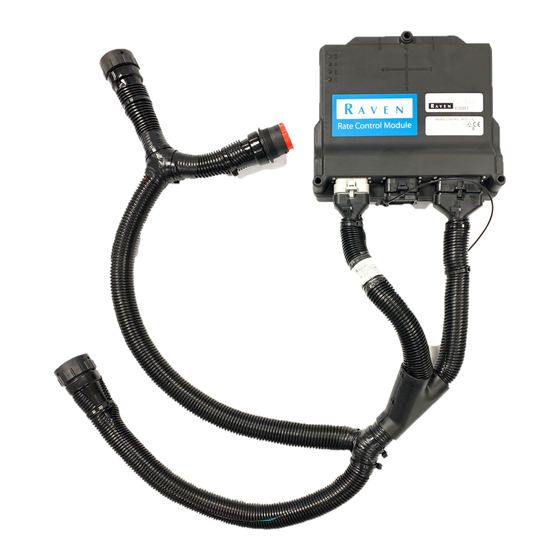
Thank you for choosing Raven Applied Technologies. The Raven Rate Control Module (RCM) is a multi-product application control system built on an ISOBUS platform. The RCM offers a machine operator with the ability to simultaneously monitor and control dry manure or litter application via ISOBUS Universal Terminal (UT) and task control for as-applied documentation, prescription rate, and section control. - Page 8 HAPTER MULTIPLE UTS When an RCM is used in a system with more than one UT (universal terminal), the RCM can be assigned a primary FIGURE 1. Set Primary UT Menu RCM DRY MANURE AND LITTER CONTROLLER OPTIONS This guide is intended to assist with the setup and configuration of the Raven Rate Control Module (RCM) on pull- type or self-propelled dry manure and litter applicators.
-
Page 9: Machine Types
RCM Level 0 does not offer dynamic calibration, cleanout mode, or gate height monitoring features. RCM LVL 0 (Scale Only) does not provide product or task control features with base functionality. These features may be unlocked to achieve dry manure and litter application control features if desired. -
Page 10: Feature Unlocks
HAPTER FEATURE UNLOCKS Many control features require specific unlock levels. If control features are not available with the RCM installed on your machine, contact your local Raven dealer or visit the Raven Precision portal at the link below to unlock additional control features if needed. -
Page 11: Calibration Wizard
C H A P T E R 3 CALIBRATION WIZARD NOTE: Complete the following calibration steps to setup an RCM Level 3 with dry manure or litter spreading features. 1. Enter the profile name for the implement. 2. Select Pull-Behind Spreader from the drop down menu. - Page 12 9. Select the Next button in the lower, right corner of the page to proceed. FIGURE 3. Setup Fan/Spinner RPM 10. Use the drop down list to select the Granular Fertilizer option. 11. Select the Next button in the lower, right corner of the page to proceed. RCM Dry Manure/Litter Setup Guide...
- Page 13 CALIBRATION FIGURE 4. Setup Application Type 12. Use the drop down list to select Dry Manure/Litter option. 13. Select the Next button in the lower, right corner of the page to proceed. FIGURE 5. Setup Application Type - Product 1 14.
- Page 14 20. Assign the “Product Scale 1” to Product 1 by placing a check mark in the box next to Product Scale 1. 21. Select the Next button in the lower, right corner of the page to proceed. RCM Dry Manure/Litter Setup Guide...
- Page 15 CALIBRATION FIGURE 8. Scale Setup 22.Enter the calibration number for the scale. Refer to Chapter 6, Machine Settings, for manufacturer scale calibration numbers. FIGURE 9. Scale Setup NOTE: The manufacturer scale calibration numbers are an initial starting point for the scale calibration. It is highly recommended to verify the scale calibration with a known weight of at least 25% of the total scale capacity, after initial scale calibration, to ensure scale accuracy.
- Page 16 28. Select the Next button in the lower, right corner of the page to proceed. FIGURE 11. Setup RPM Sensor Assignment 29. Use the Control Valve Type drop down list to select the PWM Close valve. RCM Dry Manure/Litter Setup Guide...
- Page 17 CALIBRATION 30.Valve Response Rate will be set to 50. 31. Control Deadband will be set to 2. 32.Enable PWM Smart Control box will remain unchecked. 33.Select the Next button in the lower, right corner of the page to proceed. FIGURE 12. Setup Control Valve 34.The Coil Frequency defaults to 60 Hz.
- Page 18 The system will automatically adjust the Spreader Constant based upon the Gate Height entered. Select the Next button in the lower, right corner of the page to proceed. FIGURE 14. Setup Rate Sensor RCM Dry Manure/Litter Setup Guide...
- Page 19 CALIBRATION RATE SENSOR WITH GATE HEIGHT SENSOR ENABLED NOTE: Complete the following steps to calibrate a granular product with a gate height sensor enabled. Enter a Density Factor value of “60”. NOTE: If the density value of the product is known, it is recommended to enter the known value as the Density Factor to provide a closer starting calibration from which the dynamic calibration will begin adjusting during operation.
- Page 20 49.Select the Next button in the lower, right corner of the page to proceed. FIGURE 17. Setup Rates 50. Off Rate Alarm should be set to “20”. 51. Ensure the alarm box is checked. 52. Ensure the Shaft Sensor Alarm box is unchecked. RCM Dry Manure/Litter Setup Guide...
- Page 21 CALIBRATION 53.Select the Next button in the lower, right corner of the page to proceed. FIGURE 18. Setup Alarms 54.Review the Setup Summary. 55. Select the Next button in the lower, right corner of the page to complete the profile setup. NOTE: Select the Back button in the lower, left corner of the page to return to the previous page if needed.
- Page 22 CHAPTER 3 RCM Dry Manure/Litter Setup Guide...
-
Page 23: S Preader Operation
System Menu Settings 1. From the RCM home page, select the “Tools” button along the right side of the page. 2. Select the “System Settings” tab and then the “Rate Sensor Setup” button. FIGURE 1. Setup Rate Sensor Page 3. Select the “Dynamic Cal Setup” button. - Page 24 Sensitivity percentage may be increased (not to exceed 75%). If erratic rates are observed, reduce this value (not to be set below 25%) but may lead to some variation between controller totals and scale totals. RCM Dry Manure/Litter Setup Guide...
- Page 25 Menu Settings 1. From the RCM home page, select the “Tools” button along the right side of the page. 2. Select the “System Settings” tab and then the “Rate Sensor Setup” button. 3. On the Setup Rate Sensor page, press the “Cleanout Setup” button to access the Cleanout settings.
-
Page 26: Trigger Weight
System Menu Settings 1. From the RCM home page, select the “Tools” button along the right side of the page. 2. Select the “System Settings” tab and then the “Rate Sensor Setup” button. FIGURE 5. Setup Rate Sensor Page 3. Select the "Gate Height Sensor Cal" button. -
Page 27: Manual Calibration
SPREADER OPERATION FIGURE 6. Manual Gate Height Calibration • If the specific "mV Per Length" value is known (mV/in), refer to the Manual Calibration section on page 25. • If the specific "mV Per Length" value is not known, refer to the Procedural Calibration section on page 26. - Page 28 UT Menu Tools Menu System Menu Settings 1. From the RCM home page, select the “Tools” button along the right side of the page. 2. Select the “System Settings” tab and then the “Scale Setup” button. RCM Dry Manure/Litter Setup Guide...
- Page 29 SPREADER OPERATION FIGURE 9. System Settings Menu 3. Select the Scale Calibration button at the bottom of the page. FIGURE 10. Scale Setup Page 4. Load a known weight of product into the implement tank or bin. NOTE: It is recommended to use a known weight of at least 25% of the total scale capacity to obtain a more precise scale calibration slope.
- Page 30 8. Review the confirmation prompt and select the Accept button in the lower, right corner of the page. The scale calibration has been adjusted for the known weight of product in the tank or bin. RCM Dry Manure/Litter Setup Guide...
-
Page 31: Quick Start
• With the beater running, toggle the master switch ON and press the Quick Start button in the lower, right corner of the RCM run page. The Quick Start feature will start the apron to run for up to 15 seconds while the equipment remains stopped. - Page 32 Product Main Page QUICK ACCESS SOFTKEYS The softkeys displayed along the right side of the RCM working set allow quick access to commonly used features, calibration settings, and options. Review the following sections for additional information about the RCM softkeys: HOME Touch the Home softkey to quickly return to the Home page and access the primary RCM operation information.
- Page 33 SPREADER OPERATION DIAGNOSTICS Select Diagnostics to access system information, tests, and diagnostic trouble codes (DTCs). The DTC Status indicator is displayed on the Diagnostics softkey and provides a visual indicator of Diagnostics the system status during field applications. The status indicator provides the following display states: OK.
- Page 34 HAPTER MAIN PAGE OVERVIEW FIGURE 15. Main Spreader Page Raven RCM Spreader Home Page Overview TABLE 1. Button Description Function/Operation Select a product tab to display the main page for a desired product. The Product Tabs readout area of the main page for each...
- Page 35 Section Switchbox Button • READOUT DESCRIPTIONS When the RCM is configured for dry manure or litter application, the following readouts are displayed on the main page by default. NOTE: The operator may customize readouts shown on the Main page if desired. Refer to the Raven Rate Control (RCM) Operation Manual (P/N 016-0171-637) for additional assistance with customizing readouts on the Main page.
- Page 36 The Applicator Setup Tab provides options to create a new, edit, or remove an applicator. This tab also provides a summary to the section configuration. For more information on the Precision Farming Setup button, refer to the Raven Rate Control Module Operation Manual (P/N 016-0171-637). SYSTEM SETTINGS The system settings provides access to settings and options which allow the operator to adjust the system configuration values as needed, to maintain proper control of the system.
- Page 37 FEATURE UNLOCKS To activate additional features available for the RCM, enter the Activation Key to access these features. NOTE: Contact a local Raven dealer for additional information regarding available features for your specific application and for assistance with purchasing activation keys.
-
Page 38: System Information
DIAGNOSTICS Selecting the Diagnostics button open a window with tabs for the items listed below. SYSTEM INFORMATION Displays information about the RCM including the Hardware Serial Number, Hardware Revision, and Software Version Number. TESTS The Tests tab allows the user to select various tests from a drop down list. These list of tests will vary by product configuration. - Page 39 S TAND-ALONE SCALE CHAPTER C H A P T E R 5 OPERATION STAND-ALONE SCALE INITIAL CALIBRATION 1. Select Scale as the Machine Type. FIGURE 1. Name Profile 2. Enter a Profile Name. 3. Press Next. 4. Select the check box(es) next to the desired Scale(s) you want to monitor. 016-0171-694 Rev.
- Page 40 6. Enter the Scale Total Calibration Number. Refer to Chapter 6, Machine Settings, for machine specific scale information. FIGURE 3. Scale Setup 7. Press Next. 8. Review the scale configuration on the Setup Summary page. RCM Dry Manure/Litter Setup Guide...
-
Page 41: Scale Page
9. If any of the information is incorrect, press the back button to adjust the configuration. If the configuration is correct, press Next. SCALE RUN PAGE OVERVIEW The image below is an example of a typical run page. FIGURE 5. RCM Main Page Main Setup Totals... - Page 42 Scale Graphics weight on each scale. Displays the weight on the scale. If the Gross combined weight scale is selected this will display as Net. Displays the combined weight of all the Combined Weight scales. RCM Dry Manure/Litter Setup Guide...
- Page 43 The Systems Settings Tab allows the user to modify the current scale calibration. FEATURE UNLOCKS To activate additional features available for the RCM, enter the Activation Key to access these features. NOTE: Contact a local Raven dealer for additional information regarding available features for your specific application and for assistance with purchasing activation keys.
- Page 44 DIAGNOSTICS Selecting the Diagnostics button open a window with tabs for the items listed below. SYSTEM INFORMATION Displays information about the RCM including the Hardware Serial Number, Hardware Revision, and Software Version Number. TESTS The Tests tab allows the user to select various tests from a drop down list. These list of tests will vary by product configuration.
-
Page 45: Machine Settings
M ACHINE SETTINGS CHAPTER C H A P T E R 6 The following offers recommended initial settings for OEM manufacturer. NOTE: These settings are only intended to assist with initial set up of the machine and test weight calibrations should be performed to validate and tune these settings.] OEM Machine Settings TABLE 1. - Page 46 CHAPTER 6 RCM Dry Manure/Litter Setup Guide...
-
Page 47: Limited Warranty
Bring the defective part and proof of purchase to your Raven dealer. If the dealer approves the warranty claim, the dealer will process the claim and send it to Raven Industries for final approval. The freight cost to Raven Industries will be the customer’s responsibility. -
Page 48: Extended Warranty
Bring the defective part and proof of purchase to your Raven dealer. If the dealer approves the warranty claim, the dealer will process the claim and send it to Raven Industries for final approval. The freight cost to Raven Industries will be the customer’s responsibility.
Need help?
Do you have a question about the RCM and is the answer not in the manual?
Questions and answers